Page 2
P18690
09/28/2009
HH..KK.. PPoorrtteerr®
8690 Series Disassembly and Assembly
The following disassembly and assembly procedures
apply to all models except where noted.
Disassembly:
1. Secure the tool in a vise by the right handle (handle
without the ratchet) with the left handle parallel to the
floor and the head pointing away from you.
2. TN model: Cut the rubber handle grip (P0380 ) from
the handle. Be careful not to damage the plastic sleeve.
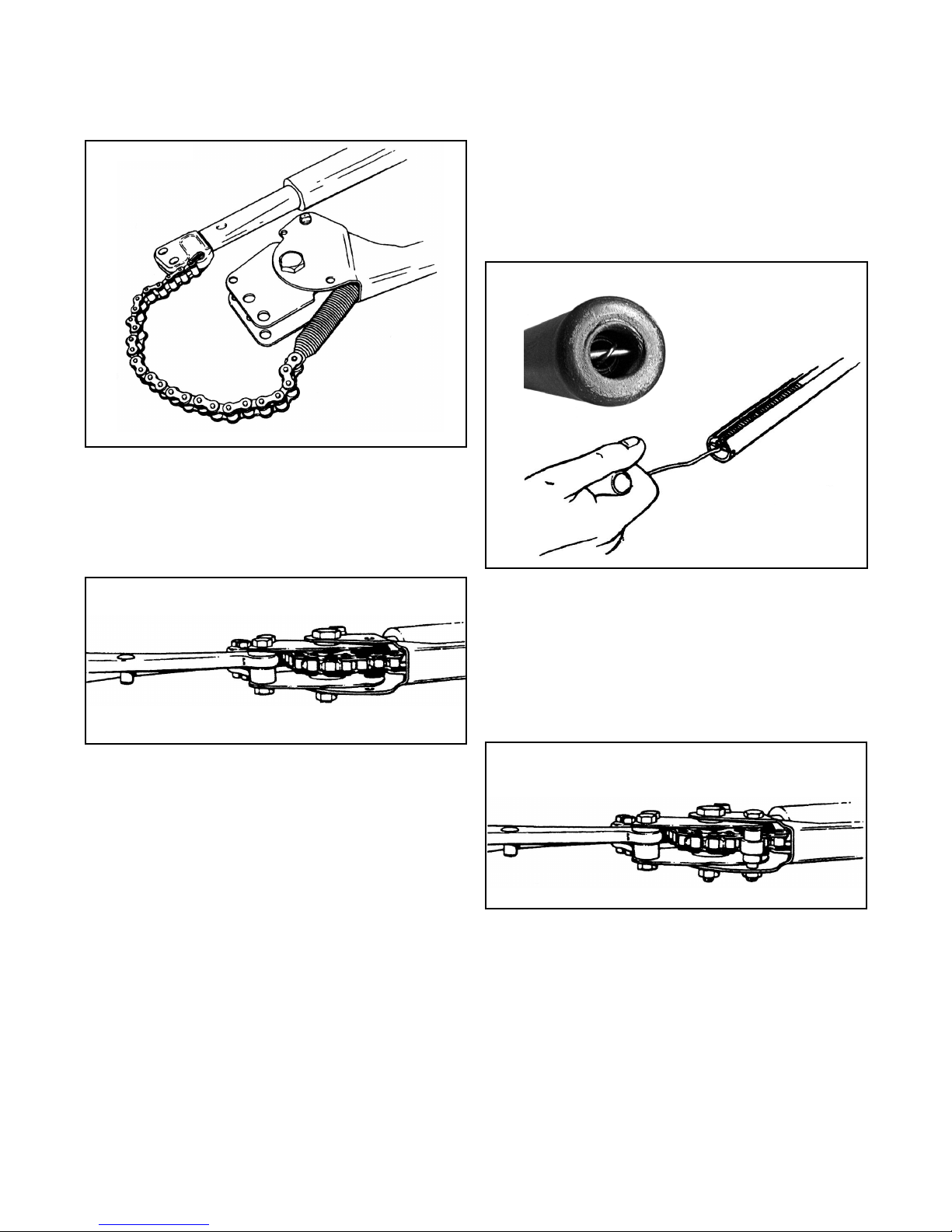
3. FH, FSK, CK, and CS models: In the end of the left
handle (the ratcheting handle), insert a hook type tool
through the access hole in the end of the handle grip,
hook the spring, pull the spring slightly towards you,
twist 90 degrees and unhook the spring (P8678FS)
from the pin. Note: removal of the handle grip is no
longer required as a result of the added access hole to
the new grip.
3a. TN model: Unhook the spring extension (P8679TN)
from the pin on the ratchet handle using a hook type
tool.
4. Loosen nut (T3171) from bolt (P8635FS) using 7/16”
wrenches.
5. Remove the bolt and snubber (P8654FS).
6. Remove the tool from the vise.
7. Unhook the two closing springs (P8658FH).
8. Remove the closing spring bolt (P8634FS), nut
(T3171) and snubber (P8654FS).
9. Remove the cutterhead from the handles using 9/16”
wrenches. Important: Note the difference in length
between the two sets of bolts.
10. Remove the right handle assembly, with the chain
and spring still attached, from the left handle.
11. Remove the nut (P2666K) from the sprocket pivot
bolt (P8692FS) using a 9/16” wrench.
12. Remove the sprocket pivot bolt (P8692FS).
13. Remove the two side plates (P8621FS), sprocket
(P8624FS), bushing (P8642FS), detent pawl
(P8637FS), and spring (P8677FS).
14. Remove the two crank plate bushings (P8646FS).
15. Clean all parts thoroughly with solvent.
Assembly:
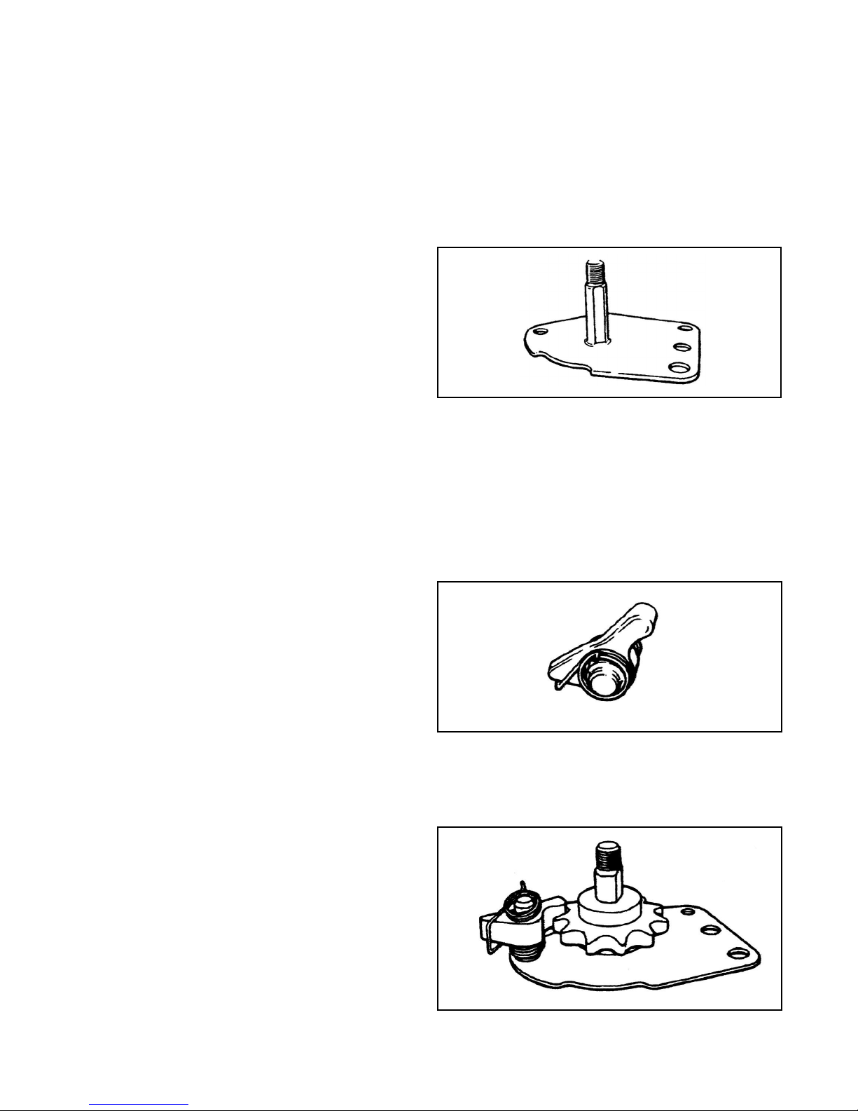
1. Assemble the pivot bolt (P8692FS) to one of the side
plates (P8621FS). atch the flat on the bolt with the flat
in the plate hole. Lay this assembly on the bench with
the bolt head down and the notched edge of the plate
nearest to you. See Illustration 1.
2. Apply a light film of grease to the shank of the pivot
bolt.
3. Slide the sprocket (P8624FS) onto the pivot bolt.
4. Apply grease to the detent spacer bushing
(P8642FS) and slide into the detent pawl. Place the
detent spring (P8677FS) onto the pin making sure the
spring ends have not been bent out of shape. The cross
arm of the spring goes under the flat side of the narrow
shaped point of the detent pawl. See Illustration 2.
5. Assemble one end of the detent spacer bushing
(P8642FS) into the hole on the side plate (P8621FS)
and engage the rounded end of the pawl with the
sprocket (P8624FS). See Illustration 3.
Illustration 1
Illustration 2
Illustration 3