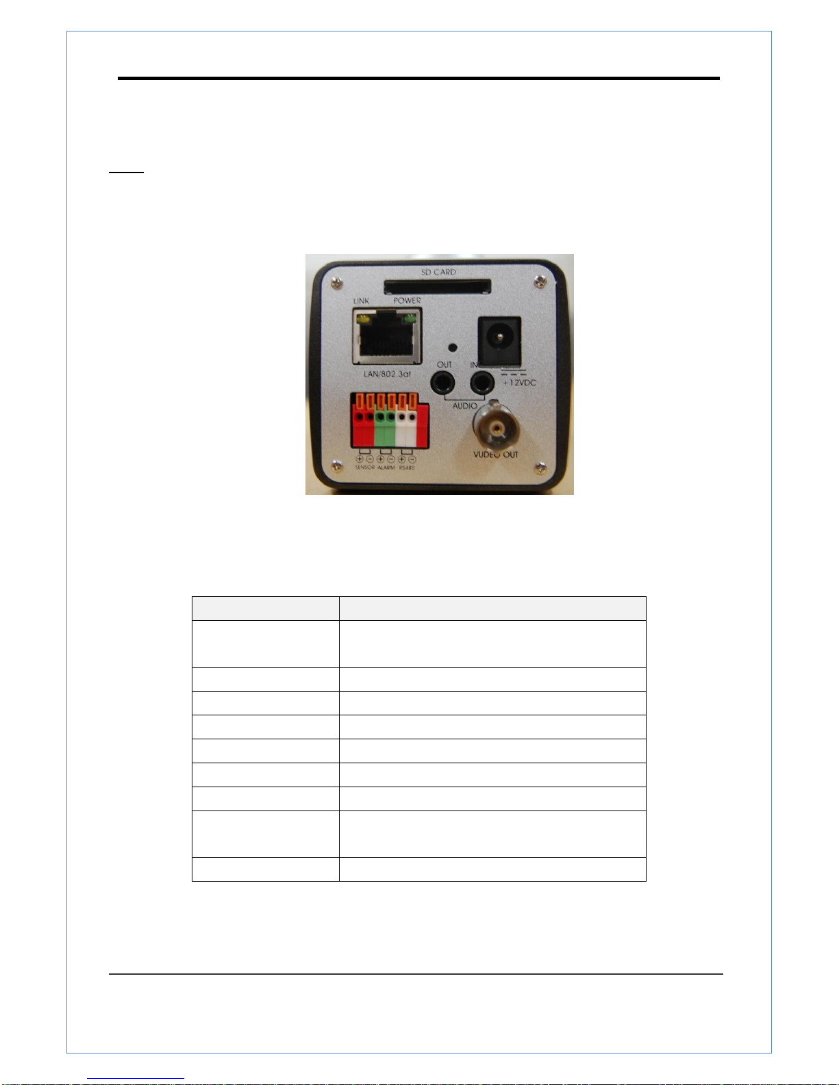
H265 COMPANY TN-B200CE User manual

User Manual ver.1.0
2 Megapixel IP Box Camera
1080P @60fps

TN-B200CE user manual
2 Megapixel IP Camera Manual
2/73
Safety Precaution
Make sure to turn off the power before installing TN-B200CE
Do not install under the direct sunlight or in dusty areas.
Make sure to use the product within the temperature and humidity specified in the specification.
Do not operate the product in presence of vibrations or strong magnetic fields.
Do not put electrically conducting materials in the ventilation hole.
Do not open the top cover of the product. It may cause a failure or electric shock on the
components.
To prevent from overheating, make sure to keep the distance at least 10cm from the ventilation
hole.
Make sure proper voltage (220V/100V) before connecting the power.
We appreciate your purchasing TN series.
Before installing the product, please read the following with care.

TN-B200CE user manual
2 Megapixel IP Camera Manual
3/73
1. Introduction
About this manual
This User Manual provides information on operating and managing the megapixel IP box camera. The
Manual includes instructions of installation, operation and configuration of megapixel IP box camera as well
as how to make troubleshooting.
Features
This product is a megapixel Box network-based camera with remote live monitoring, audio monitoring and
control via an IP network such as LAN, ADSL/VDSL, and Wireless LAN.
Video
Highly efficient compression algorithm, H.264 & MJPEG support
Wide range of transmission rates: 32kbps ~ 16mbps
Various transmission modes: CBR, VBR, Hybrid
Motion detection
Audio
Multi-transmission mode: Simplex (IP Box camera Client PC or Decoder, Client PC or Decoder
IP Box camera), Full Duplex
Network
Fixed IP & Dynamic IP (DHCP) support
1:1, 1:N support
Multicasting
Various types of Protocol support : TCP/IP, UDP, Multicast, DHCP, SMTP, HTTP, SNMP, RTP, RTSP
OnVIF, PSIA compliant
Serial Data
RS-485 support
Data pass-through mode : Serial data communication between megapixel IP PTZ camera and Decoder
Sensor and Alarm
Support direct connections of external sensor and alarm devices
Event Alarm notification.
If an external sensor is activated, camera can be set to move to the corresponding Preset position.
User Interface
Diagnose and upgrade through dedicated program called True Manager

TN-B200CE user manual
2 Megapixel IP Camera Manual
4/73
System configuration using Internet Explorer
High Reliability
Reliable embedded system
Product and Accessories
TN-B200CE
Quick Manual

TN-B200CE user manual
2 Megapixel IP Camera Manual
5/73
Part Names and Functions
Rear
Connector
Function
1. Ethernet/802.3af
Ethernet port/802.3af LED :
Booting and system check
2. RESET Button
Initialization of network setting
3. AUDIO IN
Audio input
4. AUDIO OUT
Audio output
5. POWER IN
DC 12V
6. SENSOR/ALARM
Sensor input/ Alarm output
7. RS-485
RS-485 port
8. VIDEO OUT
Composite / HD-SDI / HDMI Video output
(Depending on models)
9. SD CARD
SD memory card slot
○
1
○
2
○
4
○
5
○
6
○
7
○
8
○
9
○
3

TN-B200CE user manual
2 Megapixel IP Camera Manual
6/73
System Connections
TN-B200CE.IP Cameras can be connected in either 1 to 1 connection where one TN-B200CE.is connected
to one PC client or a decoder system or 1 to many connections where one TN-B200CE.can be connected to
several PCs and decoder systems. (TCS-2000 video server can work as a video decoder which takes the
data from a video server or IP camera, decodes and outputs analog video.)
Topology
Generally, TN-B200CE.and PC or a decoder is connected in 1-to-1 mode or 1-to many configuration.
1:1 Connection .
One TN-B200CE.is installed at a site where video images are transmitted. A PC or a decoder is installed at a
central location to receive and view the video images on an analog monitor. Audio and serial data are
transferred in either direction.
Site
Remote Center (Decoder)
Remote Center
Site
Remote Center (PC SW)

TN-B200CE user manual
2 Megapixel IP Camera Manual
7/73
or
or
or
1:N Connection .
In this configuration, a site can be monitored from many remote central locations. Although up to 64 PCs or
decoders can be connected to one TN-B200CE in the real network environment, network bandwidth can limit
the maximum connections. Functionally, the video monitoring system (VMS) software provided can replace
the decoder.
Multicast Mode
If the network supports multicasting, a large number of decoders can be used to receive video effectively
from a TN-B200CE.using a single streaming of video and audio. However, multicast mode is possible only
when network environment supports multicast.
Relay
Video and audio data can be retransmitted from a center to another center. The arrangement is useful when
the network bandwidth to the site is limited while there are more than one center want to monitor the site.
Site
Remote Center
Site
Center 1(Decoder)
Center 2 (Decoder)

TN-B200CE user manual
2 Megapixel IP Camera Manual
8/73
VMS (Video Monitoring System)
VMS (Video Monitoring System) is a Window-based remote monitoring program in order to monitor or control
video, audio, and events in real time from several IP cameras or video servers. Please refer to the VMS User
Manual for more in detail.
Site
Remote Center
Site
Remote Center (Decoder)
VMS

TN-B200CE user manual
2 Megapixel IP Camera Manual
9/73
2. Installation
Connection
Connecting Power
1. Carefully check the voltage and current capacity of the rated power. The rated power is indicated in the
back of main unit.
2. After confirming the power source, connect power adaptor and connect the 12V DC connector to the
system
Connecting Network
1. Plug network cable to Ethernet port (RJ-45 network port).
Connecting Video
1. To display video through the composite or HD-SDI port, connect each port to a monitor using BNC
coaxial cable. To display video through the HDMI port, connect the port to a monitor using HDMI cable.
2. Set Enable Preview option “ON” on the Video tab of web page.
(Please refer to the Video Configuration part)
Especially in case of using HD-SDI, video cannot be viewed if BNC coaxial cable is not used.
In case that video transmission distance is long, video data may not be transmitted due to a
reduction in the video signal. In order to prevent it, install a repeater in the middle.
In case of using HD-SD I, video can be viewed on the HD-SDI monitor
In case of using HDMI, video can be viewed on the monitor supporting HDMI
Connecting Audio
Audio is full-duplex. It is possible to set the mode as Tx-only, Rx-only or Tx-Rx.
1. Connect audio input and output ports to audio devices accordingly.
2. The Audio signal required is line level, so an audio equipment with an amp, mixer or other amplifier
should be used.
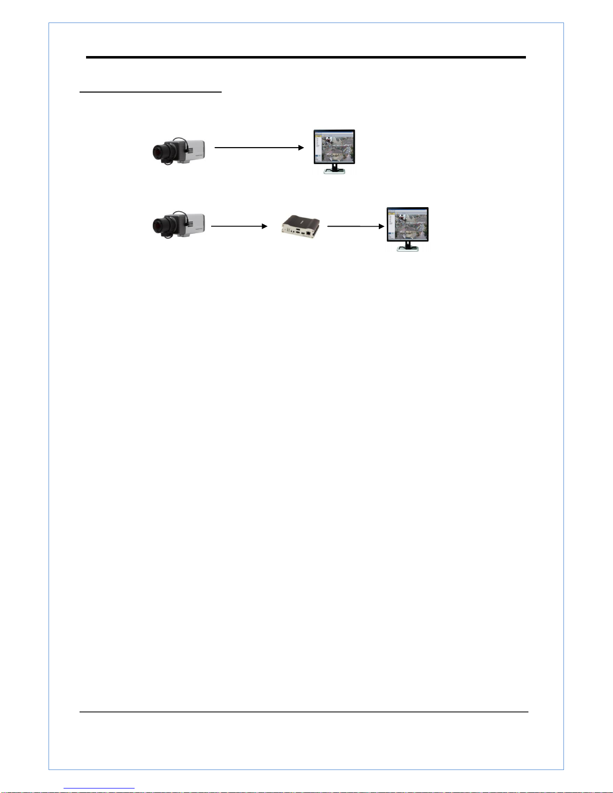
Connecting Serial Port (RS-485 Communication)
RS-485 of TN-B200CE can be connected to external equipment such as PT receiver etc. PC client can
send PT commands to the external equipment via the serial port.
When a decoder system instead of PC client is connected to TN-B200CE the serial port and that of the
decoder system works in pass-through mode. That is, data from at one port is delivered to the other
port, vice versa

TN-B200CE user manual
2 Megapixel IP Camera Manual
10/73
Connecting Sensor and Alarm
Connect sensor and alarm devices to corresponding terminals accordingly
Check if it works
Once the power is supplied to the camera, it will start booting. The system will boot up to an operating mode
after approximately 40-60 seconds. The green LED on the Ethernet port will flash indicating the system is
ready.
The software provided in the CD called True Manager allows you to check the IP address and other network
details of the camera. Please refer to the True Manager manual for instructions on how to find the IP address
of the camera and change it if required.

TN-B200CE user manual
2 Megapixel IP Camera Manual
11/73
3. System Operation
Remote Video Monitoring
There are two ways to monitor video when the center system and IP camera are connected. In order for
a proper operation, an IP address must be set accordingly. Please refer to True Manager Manual
enclosed with product for further details.
Default ID : admin
Default Password :1234
Video Monitoring using Internet Explorer
Open Internet Explorer and enter camera’s IP address. The system will ask for confirmation to install
Active-X control. Once authorized, the Internet Explorer will start to display video images from camera
as shown below.
Defalut IP Address : http://192.168.10.100

TN-B200CE user manual
2 Megapixel IP Camera Manual
12/73
Video Select
Select the Video stream to be viewed : Primary, Secondary, tertiary or quartic streaming. This camera is
capable of dual streaming; primary streaming and secondary streaming..Video will be displayed
according to the resolution set on video configuration. If dual streaming (“Use Dual Encode” Menu in
Video page) is not activated, secondary video is not available
View Size
Adjust the size of the screen.
Screen size if initially adjusted according to the compression resolution. Click on 50% icon and the
whole screen size will be reduced to half size.
Digital Zoom
Control the Digital zoom on the screen
The more the camera zooms in, the smaller the square of control panel is. Position of the image can be
changed by moving position of the square. If you press x1, the screen will return to the normal size.
PTZ Control (Optical Zoom & Digital Zoom Built-in the Camera)
Control PTZ and PTZ Control Panel is used for controlling external PTZ devices when the external PTZ
devices are connected through serial port. It is possible to make zooming control by Zoom in/out

TN-B200CE user manual
2 Megapixel IP Camera Manual
13/73
buttons of PTZ control Panel (In order to use digital zoom, select Digital zoom ON in the Camera tab)
- Stop
Stop on-going action
- Focus Near, Focus Far, Auto Focus
Adjust the focus of the lens
Select Preset
Set preset position and move to the specific preset position.
- Goto
Move to the selected preset entry if the preset entry is set.
- Set
Set the current position to the selected preset entry.
- Clear
Delete the selected preset entry.
Sensor Input and Alarm Output
Display the status of the sensor in real time.
This camera supports one sensor input. When the sensor of the camera is working, the sensor light
turns red Operate the alarm device by pressing the number icon. This camera supports one alarm
output. A number icon indicates status of the alarm device.
Snapshot
Capture video images and store them as BMP or JPEG files.
Talk
Transfer audio from PC’s mic to the camera.

TN-B200CE user manual
2 Megapixel IP Camera Manual
14/73
File Record
Recording to an AVI file on Live View page is available. AVI files are generated in the specified folder or
in a specified file name on the PC where web browser is running.
1. Press “Set” button to select a folder or create a new folder. Enter the file name on a filename field.
2. Press “Start” button to start recording.
3. Press “Stop” button to stop recording.
4. An AVI file named “IP address_hh_mm_ss” or “File name_IP address_hh_mm_ss” will be generated
in the specified folder depending on where the path specified folder
or a prefix of the file name.
Display Buffer
Set the number of video frames to be buffered before being displayed on web browser. Larger value
results in smoother video by sacrificing the latency. Asetting of 10 ~ 15 frames can be used generally for
most situations.
Video Monitoring with Decoder System
Once camera’s IP address is set in the remote IP address section of the decoder, the decoder system
will connect to camera and start receiving the video images. Normally, a monitor connected to the
decoder will display video images
Initialize of IP Address
If a system IP address is lost, the system can be reset to the system default IP address using the reset
button in the back side of the system.
1. While the system is in operation, press the reset button for more than 5 seconds.
2. The system will reboot automatically.
3. Once the system reboots, IP address will be set to the system default as below;
IP mode
Fixed IP
IP address
192.168.10.100
Subnet mask
255.255.255.0
Gateway
192.168.10.1
Base port
2222
HTTP port
80

TN-B200CE user manual
2 Megapixel IP Camera Manual
15/73
4. Remote Configuration
Using Web Browser
Remote setting is available by using web browser. Enter IP address of camera and then a live view
screen appears as below. Press Setup button located in the upper right area of the monitoring screen to
go to the server setup. For Remote Setting, user should be authorized higher than manager level.
The configurations are grouped into 9 categories: Video & Audio, Image, Network, Event, Record,
Device, PTZ, System, User. Leaving the page without pressing Apply button, any changes in the page
will be discarded.
Enter IP Address
Press Setup button

TN-B200CE user manual
2 Megapixel IP Camera Manual
16/73
Video & Audio
Information
The information provides current information regarding the settings for video and Audio

TN-B200CE user manual
2 Megapixel IP Camera Manual
17/73
Video
- Performance Calculation
Shows the performance usage rate according to the value set at ‘Encode’ mode underneath.
- Input Frequency
User can select NTSC type or PAL type
- Resolution
Select video encoding solution.
Scaling option is used when encoding resolution is different from input resolution. Without Scaling

TN-B200CE user manual
2 Megapixel IP Camera Manual
18/73
option, input video will be cut according to encoding resolution. On the other hand, if Scaling is
selected, input video will be adjusted according to encoding resolution.
- Framerate
Determine the maximum number of frames per second for the video stream.
1,2,3,4,5,6,8,10,15,20,25,30 and 60 frame rate can be selected. The actual frame rate of video can
be less than the maximum frame rate set due to the network bandwidth limitation
- Preference
Select encoding mode to control video quality or bitrate: Quality(VBR) or Bit rate(CBR). If ‘Bitrate’
selected, the video encoding will be effected by the ‘Bitrate’ value entered. Therefore, “Bitrate” mode
corresponds to CBR (Constant Bit rate) encoding. If ‘Quality’ selected, the video encoding will be
effected by the quality of image selected. Therefore, “Quality” mode corresponds to VBR (Variable
Bit Rate) encoding.
- Quality
Select Video quality. 7 levels of quality are available.
Quality mode (VBR encoding) tries to encode every frame in a constant quality. Therefore, resulting
bitrate may vary a lot depending on the complexity or activity changes in the input video. It is
preferred when constant video quality is required and network bandwidth is enough for delivering
the stream of highly varying bitrate.
- Bitrate
Determine bitrate value between 32 ~ 16Mbps.
Bitrate mode (CBR encoding) allows you to set a fixed target bitrate that consumes a predictable
amount of bandwidth. In order to keep the bitrate limit, video quality is controlled dynamically
according to the complexity or activity changes in the input video.
- I-Frame Interval
Determine I-frame Interval between 1 and 255.
- H.264 Profile
Select H.264 Profile : High Profile or Baseline Profile
The standard defines various sets of capabilities which are referred to as profiles,
targeting specific classes of application.

TN-B200CE user manual
2 Megapixel IP Camera Manual
19/73
I. High Profile
The Primary profile for broadcast and disc storage applications, particularly for high-definition
television application.
II. Baseline Profile
Primarily for low-cost applications that require additional data loss robustness, this profile is
used in some videoconferencing and mobile application. This profile includes all features that
are supported in the constrained baseline profile, plus three additional features that can be
used for loss robustness.
- Secondary #1 ~ #3
- Use Dual Encode
Select ON to enable to use Secondary #1 ~ #3.
The Secondary #1 ~ #3 video can be viewed on Live View window by selecting Stream number on
Video selection
- ROI Encoding
Select ON to enable to use ROI. User can make an area for ROI on Secondary stream.
- Algorithm
Select H.264 or MJPEG for the secondary, tertiary or quartic streaming.
In case of H.264, wither bitrate mode or Quality mode can be selected for Preference mode in. On
the other hand, MJPEG supports Quality mode3

TN-B200CE user manual
2 Megapixel IP Camera Manual
20/73
Audio
Algorithm
Select the audio algorithm: G.711 or AAC
G.711 and AAC from client to server direction are supported. Thus, bidirectional audio
communication is supported.
Bit rate
Select the bitrate between 64Kbps and 128kbps when AAC is selected
The sampling rate is fixed to 8KHz and 32KHz for G.711 and AAC respectively.
Note that when camera is connected to a decoder, the decoder’s audio algorithm should be set
identically to transmit audio properly.
Mode
Select audio operation mode
Mode
Action
Off
No operation
Tx-Only
Transmit only
Rx-Only
Receive only
Tx & Rx
Transmit and Receive
Input Gain
Set audio input gain from 0 to 31.
Table of contents