H2flow FaraMag FM500 User manual

FaraMag™ mag meter
IMPORTANT NOTE: For the most up-to-date version of this manual, please visit www.h2flow.net/product-literature
English
Rev.1.2
6/2020
www.h2flow.net •Tel: 888-635-0296 (Toll Free) OR (+1) 419-841-7774 (International)
Operating Manual (EN)
FM500 MODELS

www.h2flow.net •Tel: 888-635-0296 (Toll Free) OR (+1) 419-841-7774 (International)
table of contents
Description .............................................................................................................3
Flow Ranges ..........................................................................................................3
Technical Data ......................................................................................................4
Dimensions.............................................................................................................5
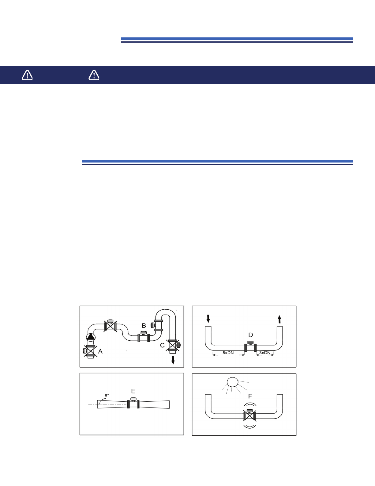
Installation Note ....................................................................................................6
Location ...................................................................................................................6
Electrical Connections ......................................................................................7
Instrument Start ...................................................................................................9
Instrument Configuration ................................................................................9
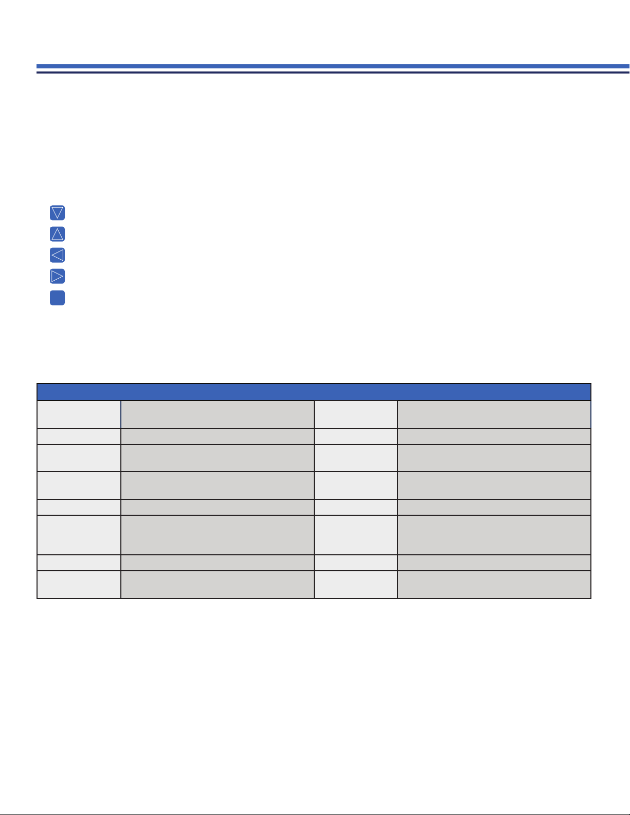
A. menu options, commands........................................................................ 10
B. multi-functional outputs............................................................................. 11
B-1. pulse setting .................................................................. 11
B-2. status report setting ................................................... 12
C. analog output............................................................................................... 12
D. display ................................................................................................... 13
E. damping ................................................................................................... 13
F. dead band setting ....................................................................................... 14
G. datalogger ................................................................................................... 14
G-1. datalogger setting without time mask................... 15
G-2. datalogger setting with time mask........................ 15
G-3. examples of time mask setting............................... 16
G-4. datalogger sub-menu................................................ 16
H. function of the third electrode................................................................ 17
I. password setting........................................................................................... 17
J. GSM module activation.............................................................................. 18
Troubleshooting...................................................................................................18
Notes.........................................................................................................................19
Warranty .................................................................................................................. 20
2
SECTION
1
2
3
4
5
6
7
8
9
10
11
12

www.h2flow.net •Tel: 888-635-0296 (Toll Free) OR (+1) 419-841-7774 (International)
1. description
The induction FM500 is designed for measuring both clean and waste water in water management applications.
The product is characterized by high accuracy and stability of flow rate measurement in whole range of flow rates from 0.33
to 33 ft/s in both directions for liquids ≥ 10µs/cm.
Measured values are displayed on a large graphical display, which is a standard component of the instrument as well as a
keyboard and three programmable isolated outputs for remote transmission of measure values. Two of these outputs can be
used as pulse or status outputs and the third one as an active current output. The standard delivery also includes an internal
data logger and RS232 communication port.
A GSM module for remote data reading via SMS text message can be ordered as an option.
Setting of flow meter parameters is performed using the keyboard and intuitive display menu or using service software via the
RS232 communication port.
3
2. flow ranges
GPM PIPE DIAMETER (inches)
1” 2” 3” 4” 6” 8” 10” 12”
Minimum 0.79 3.17 7.93 12.68 28.53 50.72 79.25 111
Maximum 79 317 793 1,268 2,853 5,072 7,925 11,095
14” 16” 20” 24” 28” 32” 36” 40”
Minimum 152 198 317 444 610 793 1,007 1,244
Maximum 15,216 19,813 31,700 44,380 61,023 79,251 100,649 124,425
NOTE: Please consult the factory for accurate flow range data for models smaller than 1-inch in diameter and larger than
40-inches in diameter.

www.h2flow.net •Tel: 888-635-0296 (Toll Free) OR (+1) 419-841-7774 (International)
4
3. technical data
TECHNICAL DATA
NOMINAL DIAMETER 1/2” TO 40” (larger diameters available upon request. Please contact factory)
PRESSURE RATING 145 psi (PN10) and 232 psi (PN16) 363 psi (PN25) and 580 psi (PN40)
TUBING CONNECTION ANSI Flanges (optional DIN 2633)
MEASURING TUBE INTERNAL COATING Rubber, PTFE
SENSING ELECTRODES 316L AISI stainless steel, Hastelloy 2 x measuring / 1 x indication of empty tube / 1 x ground
FLOW RANGE 0.29 - 31,700 GPM
MEASUREMENT ERROR ±0.25% of the measured value from 1.64 - 32.8 ft/s
±1.0% of the measured value from 0.33 - 1.64 ft/s
STORAGE TEMPERATURE 32 - 113˚F (0 - 45˚C)
WORKING TEMPERATURE 14 - 194˚F (-10 - 90˚C) for Hard Rubber lining
-22 - 302˚F (-30 - 150˚C) for PTFE lining
VOLTAGE 230VAC (standard); 12/24 VAC/VDC (optional)
INPUT POWER 10 VA max.
OUTPUTS
1 x programmable multi-functional (pulse, status), isoluated (relay, load 125 V - /1A or 30V/2A)
1 x programmalbe multi-functional (pulse, status), isolated (transistor NPN, load 30V/50mA max.)
1 x programmable active current (0-20mA / 4-20mA, load ≤500)Ω
1 x RS232
COMMUNICATION RS232, keyboard, permanently backlit graphical display, SMS via internal GSM module
DATALOGGER capable of recording up to 100 samples
PROTECTION IP67: sensor / IP65: converter (compact version)
IP67/68: sensor / IP65: converter (remote version)
NOTE: FaraMag utilizes a standard 230VAC 12/24/VAC/VDC
power supply. An optional 12/24/VAC/VDC that needs to be
plugged into a standard receptacle is also available. The power
supply cord should be firmly inserted into the receptacle. Contact
the factory for additional information about power supply options.

www.h2flow.net •Tel: 888-635-0296 (Toll Free) OR (+1) 419-841-7774 (International)
5
4. dimensions
In the table below, the dimensions of the remote sensor version are shown. For the compact version, repace the “A”
dimension (for the connection box) with the height of the electronic unit.
ANSI version flanges meet the requirements of the ANSI B 16.5 standard. DIN version flanges comply with regulations of
standard EN1092.
DIMENSIONS OF THE SENSOR (remote version, ANSI flanges)
Diameter (Inches) L A D Weight
lbs. (kg)
Inches (mm)
0.5 5.90 (150) 5.71 (145) 3.5 (88.9) 6.6 (3.0)
0.75 5.90 (150) 5.90 (150) 3.90 (98.6) 7.7 (3.5)
15.90 (150) 6.10 (155) 4.25 (108) 8.8 (4.0)
1.25 5.90 (150) 8.66 (220) 4.62 (117.3) 10.6 (4.8)
1.5 5.90 (150) 9.06 (230) 5.0 (127) 11.0 (5)
27.87 (200) 9.45 (240) 6.0 (152) 17.6 (8)
2.5 7.87 (200) 10.23 (260) 7.0 (178) 19.8 (9)
37.87 (200) 10.83 (275) 7.5 (191) 24.3 (11)
49.84 (250) 11.81 (300) 9.0 (229) 33.1 (15)
59.84 (200) 13.19 (335) 10 (254) 44.9 (19)
611.81 (300) 14.17 (360) 11 (279) 55.7 (23)
813.78 (350) 16.93 (430) 13.5 (343) 81.6 (37)
10 15.75 (400) 18.90 (480) 16 (406) 105.8 (48)
12 19.69 (500) 19.21 (488) 19 (483) 156.5 (71)
14 19.69 (500) 23.43 (595) 21 (533) 185.2 (84)
16 23.62 (600) 25.39 (645) 23.5 (597) 249.1 (113)
20 23.62 (600) 29.53 (750) 27.5 (699) 392.4 (178)
24
PLEASE CONSULT FACTORY FOR ACCURATE WEIGHTS & DIMENSIONS
28
32
36
40

www.h2flow.net •Tel: 888-635-0296 (Toll Free) OR (+1) 419-841-7774 (International)
6
5. installation note
If the instrument has been disconnected from it’s power supply for a period of more than 6 months, the internal clock battery
may be empty. It is recommended to check the time and date when putting the instrument into operation after extensive
downtime.
The battery will be automatically charged after the instrument has been connected to the power supply.
IMPORTANT
6. location
To ensure that the instrument functions correctly, the measuring section of the induction flow meter sensor - measuring tube
- has to be completely flooded with the measured liquid and the measuring section cannot be influenced by any disturbing
elements, such as valves, pumps, bends or sharp deviations in the tubing section.
Please observe the following instructions when installing the flow meter into the tubing:
1. If the system includes pumps, never place the flow meter sensor into the pump intake (A).
2. Place the flow meter sensor into the lowest point of the horizontal part of the tubing or into the ascendant tubing (B);
never place the sensor into the tubing in the flow top-down direction (C).
3. Ensure that steady (straight) parts of tubing are a minimum of 5 x inches before the instrument and 3 x inches behind the
instrument (D).
4. Tubing reductions with a slope up to 8ºare considered straight (E).
5. Prevent the instrument from being exposed to vibrations or direct sunlight (F).

www.h2flow.net •Tel: 888-635-0296 (Toll Free) OR (+1) 419-841-7774 (International)
7
7. electrical connections
1. Ensure that the flow sensor frame is connected to ground (⏚); it is recommended that the ground
terminal at the outside of the sensor is used for this purpose. This will prevent against undesirable
interference, particularly for detached versions when shielding the link cable between the sensor
and electronic unit while connected to the frame.
Remove the upper cover of the instrument to gain access to terminals for the power cable and
the signal cables.
CAUTION
PLEASE BE AWARE THAN AN INDUCTION FLOW METER IS AN ELECTRONIC DEVICE;
THE FOLLOWING STEPS SHOULD BE PERFORMED BY A QUALIFIED ELECTRICIAN!
TERMINAL BLOCKS
Terminal Description
FLOW C tube flooding indication electrode
FLOW A measuring electrode
FLOW B measuring electrode
FLOW ⏚ground terminal of the sensor
PWR D solenoid
PWR E solenoid
BIN1 programmable multi-functional output
BIN2 programmable multi-functional output
ANAL programmable analog output
FREQ frequency output (for calibration only)
230 V L phase conductor 230V / 60 Hz
230 V PE protective conductor
230 V N neutral conductor 230V / 60 Hz
AC/DC L supply conductor +/-
AC/DC PE protective conductor
AC/DC L supply conductor +/-
PO1 protective fuse 100 mA design with 230 V/50 Hz
supply protective fuse 1A design with AC/DC supply
COMPACT VERSION
REMOTE VERSION
Control module
Sensor

8
www.h2flow.net •Tel: 888-635-0296 (Toll Free) OR (+1) 419-841-7774 (International)
2. Connect the flow sensor link cable to ABCDE ⏚terminals. (Not applicable for compact version, where the sensor was
connected in factory).
Terminal blocks on the sensor and on the electronic unit are labeled identically, so terminals A - A, B -B, C - C, D - D, E - E,
⏚ - GND have to be interconnected. Connect the shielding of the link cable only on the side of the sensor to the ground
terminal on the terminal block of the sensor. Standard length of the link cable between the sensor and the electronic unit
is 6 meters. The link cable is included in delivery. The standard length of the interconnection cable between the sensor
and the electronic unit is 20 feet. The interconnection cable is included as standard with the product.
Maximum length of the link cable is 82 feet (optional). The link cable should be always connected before the power
supply is connected to the transducer.
If the power cable has already been connected to the transducer, connecting and disconnecting of the link cable when
the transducer is under voltage is prohibited.
3. The induction flow meter is powered by mains voltage 230V / 60Hz connected to the power supply terminal block
labelled as L - PE - N, or by low voltage 12 VDC or 24 VAC connected to terminals labeled L - PE - L.
The polarity of supply conductors makes no dierence in case of using the 12 V DC power supply.
Connect the power cable to the terminals.
The induction flow meter does not have its own ON-OFF switch, so it must be fused and switched ON-OFF in another
device, such as a switchboard.
The protection of electric circuits is ensured by protective fuse T100mA, or 1A for the 12 - 24 V version, located next to the
power terminals.
Switch power supply on only after the sensor link cable and external device signal cables are connected!
4. Connect external devices that utilize current output or pulse outputs to terminals BIN1, BIN2, and ANAL. All outputs are
isolated.

www.h2flow.net •Tel: 888-635-0296 (Toll Free) OR (+1) 419-841-7774 (International)
9
8. instrument start
1. When the power supply is switched on, the instrument display shows step-by-step messages POWER ON and TEST INT
CL 1 to TEST INT CL 30.
2. After completing internal tests, the instrument enters to measuring mode. Basic data includes immediate flow rate and
total volume in positive and negative flow directions.
To display the next page, press the button. This page displays the dierence between total volumes DELTA V, total
operating hours from initial start of the instrument and the value of the maximum flow rate 100%FLOW. The next page
displays the highest and the lowest immediate flow rate reached at a particular measuring point.
3. Briefly press the EXE button to display the last line of the data logger. The line number is displayed in the upper-right
corner and its maximum value is 100. Press the or button to scroll up or down a line in the display.
The data logger line (one screen of display) shows time data (date, hour, minute) and total volumes in particular time.
In addition to this data, the instrument will also display one of the following optional values:
Immediate flow rate Q
Maximum flow rate reached during particular period MAX
Minimum flow rate reached during particular period MIN
Average flow rate reached during particular period AVR (Average)
Briefly press the button to return the instrument to basic mode. The instrument will automatically return to basic mode
after approximately 60 seconds of inactivity.
EXE
9. instrument configuration
This manual describes configuration of only those parameters that are useful to be changed when the instrument is used in a
typical way.
We do not recommend changing of parameters other than those mentioned in this manual.
Detailed description of software is included in technical documentation for service engineers.
Press the button and hold it for approximately 3 seconds to switch the instrument from ‘Measuring Mode’ to ‘Main Menu
Mode’.
EXE
WARNING
IF THE INSTRUMENT IS PASSWORD PROTECTED, YOU WILL HAVE TO ENTER THE PASSWORD TO OPEN
THE MAIN MENU.
WHEN THE TEXT ‘PASSWORD’ IS DISPLAYED ON THE SCREEN, THE PASSWORD - WHICH MAY CONSIST
OF UP TO 8 CHARACTERS - SHOULD BE ENTERED.

www.h2flow.net •Tel: 888-635-0296 (Toll Free) OR (+1) 419-841-7774 (International)
10
A. Menu options, commands
Main menu options are displayed in sixteen lines.
You may select the English, Italian, Spanish, or German language for communication. English is pre-set as standard.
Use the following keys to select an option:
scroll down by one line
scroll up by one line
move to the left by one position; also returns to the beginning of the menu in the main menu
move to the right by one position; also shifts to the end of the menu in the main menu
confirm selection
Cursor is blinking in the position of the option selected
EXE
MAIN MENU OPTIONS
RETURN Return to previous LANUGAGE Language selection (English, Italian, Spanish,
German)
ANALOG OUTPUT Configuration of analog output PULSE OUTPUTS Configuration of multi-functional (pulse) outputs
COMPARATOR Selection of logical functions for multi-functional
(pulse) outputs FREQUENCY OUT. Configuration of frequency output
DAMPING Instrument damping COMMUNICATION Configuration of communication ports (RS232, GSM
modem)
DATALOGGER Configuration of internal data logger SIMULATION Flow simulation
SENSOR Downloading of sensor calibration parameters,
setting of the flow range measured MEASUREMENT
Permit to measure the flow in negative direction,
setting of the zero flow zone, configuration of the
empty tubing detection function
TIME Configuration of internal real-time clock PASSWORD Password setting
DISPLAY Selection of immediate flow rate units and displayed
decimal places of counters SERVICE Counter reset, check of the AD transducer function,
information on software version

www.h2flow.net •Tel: 888-635-0296 (Toll Free) OR (+1) 419-841-7774 (International)
11
B. Multi-functional outputs
The flow meter is equipped with two multi-functional outputs. Relay or optotransistor contacts are connected to BIN1
terminals, while BIN2 terminals are used for optotransistor only. Use jumper NC-OC-NO above BIN1 terminals to set their
function.
a) Output works as optotransistor
b) Relay contacts are normally open
c) Relay contacts are normally closed
Outputs can function as:
a) Pulse transmitter
• of total volume in positive direction imp V+
• of total volume in negative direction imp V-
• of total volume in both directions imp V
b) Status output
B-1. Pulse setting
Volumes 0.1 l, 1 l, 10 l, 100 l, 1 m3, 10 m3, 100 m3 and widths 10 ms, 20 ms, 40 ms, 80 ms, 160 ms, 320 ms, can be assigned to
transmitted pulses.
WARNING
THE FLOW METER TRANSMITS THE NUMBER OF PULSES CORRESPONDING TO THE LIQUID QUANTITY
FLOWED DURING A MEASURING CYCLE OF 640 MS. PULSE CAN BE ASSIGNED ONLY SUCH VOLUME
AND WIDTH SO THAT THE NUMBER OF TRANSMITTED PULSES DURING TIME UNIT IS REAL! INCORRECT
SETTING IS INDICATED BY AN ERROR MESSAGE. DISPLAY SHOWS THE CODE E5.
1. Use the cursor keys to select the option PULSE OUTPUTS from the main menu and confirm your selection with the EXE
key. A sub menu will be displayed.
2. Select PULSE WIDTH under options ms/imp1(2) and assign required volume to the pulse under option l/imp (2).
3. Select option OUT1 (output to terminals 1 - 2) or OUT2 (output to terminals 3 - 4) and confirm your selection with the EXE
key.
4. Select V+ from menu (output transmits pulses only for flow in positive direction), V- (output transmits pulses only for flow in
negative direction) or V(output transmits pulses for both directions) and confirm by pressing the EXE key.
5. Select the RETURN option to complete the set-up.
The instrument will ask if you want to save the new parameters by displaying the text SAVE SETUP? To confirm, select YES.
The flow meter will save the new parameters and switch to normal display mode. If NO is selected, parameters will not be
saved.

www.h2flow.net •Tel: 888-635-0296 (Toll Free) OR (+1) 419-841-7774 (International)
12
The instrument will switch to display mode and begin working with the new parameters until it is switched o. When the
instrument is switched on again, it will work with the original/default parameters.
B-2. Status report setting
1. Use cursor keys to select the option PULSE OUTPUTS from the main menu and confirm your selection by pressing the
EXE button. A submenu will be displayed.
2. Select the option OUT1 (output to terminals 1 - 2) or OUT2 (output to terminals 3 - 4) and confirm your selection by
pressing the EXE button.
3. Select the option COMP1(2) from menu (to assign status function to output) and confirm by pressing the EXE button.
If status function COMP1(2) is assigned to outputs, further setting of this function will be performed under the option
COMPARATOR in the main menu.
4. Select and confirm this option to display the submenu with direct setting of flow levels for changing of output status
(submenu options Qa, Qb), mode indicating active status of the output COMP1(2) (e.g., Q<Qa) and hysthersis.
HYST. Complete this setting in the same manner described in Section B-1, paragraph 4.
C. Analog output
The flow meter is equipped with programmable active current output on terminals ANAL. The output can be configured for
4-20 mA or 0 - 20 mA.
1. Use cursor keys to select the option ANALOG OUTPUT from the main menu and confirm your selection by pressing the
EXE button. A submenu will be displayed.
2. Select the option Ia and confirm your selection by pressing the EXE button.
3. In the submenu, select the mode of current output: 4 - 20 mA, 0 - 20 mA, or OFF (if the output is to be disabled) and
confirm by pressing the EXE button.
4. Use the option OUTPUT to select whether the current output is is to be enabled only for positive flow direction (Q+), only
for negative flow direction (Q-), or for both flow directions (Q) and confirm by pressing the EXE button.
5. In the submenu option MAX, use command EDIT and press the EXE button to enable editing of the flow rate value
corresponding with the current value for 20 mA. Use the cursor keys to set flow rate value in l/s and confirm by pressing
the EXE button.
6. Select the RETURN option to complete the setup.
The instrument will ask if you want to save new parameters by displaying the text SAVE SETUP?. Select YES to confirm. The
flow meter will save the new parameters and switch to the normal display mode. If NO is selected, parameters will not be
saved.
The instrument will switch to display mode and work with the new parameters until it is switched o. When the instrument is
switched on again, it will use the original/default parameters.

www.h2flow.net •Tel: 888-635-0296 (Toll Free) OR (+1) 419-841-7774 (International)
13
E. Damping
Adverse eect of sudden changes of flow rate or laminar flow disturbances in measuring section of the instrument (e.g., due
to fittings, bends or pumps) sensed by the instrument and causing sudden changes of displayed values or oscillations of
current output can be eliminated by setting of instrument damping.
1. Use cursor keys to select the option DAMPING from the main menu and confirm your selection with the EXE button. A
submenu will be displayed.
2. Select option TIME and confirm your selection by pressing the EXE button.
3. Select TIME CONSTANT from the submenu and confirm it by pressing the EXE button. Generally, the longer the time
constant is, the more stable the value is on the display and on the outputs; however, this option is also slower to respond
to flow changes, i.e., with time constant of 5 seconds, the instrument responds to an immediate drop of flow and displays
zero flow rate only after 5 seconds.
4. Select the option MODE and confirm by pressing the EXE button. Select LINEAR if damping is to be linear or AVERAGE
if it should be calculated from several saples depending on selected time constant. Confirm your selection by pressing
the EXE button.
5. In option ZONE, select the command EDIT and press the EXE key to enable editing of bandwidth above and below stead
flow mean value in which damping should occur. Use the cursor keys to set numeric value in l/s and confirm it by pressing
the EXE button.
6. Select the RETURN option to complete the setup.
The instrument will ask if you want to save new parameters by displaying the text SAVE SETUP?. Select YES to confirm. The
flow meter will save the new parameters and switch to the normal display mode. If NO is selected, parameters will not be
saved.
The instrument will switch to display mode and work with the new parameters until it is switched o. When the instrument is
switched on again, it will use the original/default parameters.
D. Display
Measuring units and decimal point position are set by default in the factory and correspond to the size of the flow meter.
If this default setting does not conform to your requirements, you can change it in the main menu using the DISPLAY option,
and in the submenu using by selecting UNIT (units of immediate flow rate) and DECIMAL POINT (selection of places after the
decimal point for flowed quantity).

www.h2flow.net •Tel: 888-635-0296 (Toll Free) OR (+1) 419-841-7774 (International)
14
F. Dead band setting
Basic dead band of the instrument near the zero flow rate is 0.1 l/s. This dead band can be changed so that it would be
possible to suppress undesirable flow rate values occurring due to liquid surges and vibrations in tubing at the zero flow rate.
WARNING
EXTENSION OF THE DEAD BAND INCREASES MEASUREMENT ERROR AT LOW FLOW RATES. HENCE,
PARASITIC MOVEMENTS OF LIQUID SHOULD BE ELIMINATED FIRST.
1. Use the cursor keys to select the option MEASUREMENT from the main menu and confirm your selection with the EXE
button.
2. Under the ZERO option, select the command EDIT and press the EXE button to edit the band size in l/s, in which no flow
rate is to be registered. Use the cursor keys to set the numeric value in v l/s and confirm with the EXE button.
3. Select the option RETURN to complete the set up.
The instrument will ask if you want to save the new parameters by displaying the text SAVE SETUP?. Select YES to confirm
and the flow meter will save the new parameters and switch to normal display mode. If NO is selected, parameters will not be
saved.
The instrument will switch to display mode and work with the new parameters until it is switched o. When the instrument is
switched on again, it will use the original/default parameters.
G. Datalogger
The internal datalogger enables recording of measured values in chosen intervals (either periodically or one at a time) and
their storing in the instrument’s memory.
Stored values can be subsequently read on the display or on a PC via the RS232 communication link.
The datalogger records the following parameters by default: total volume in positive direction V+, total volume in negative
direction V-, instrument status at the moment of reading Exx, and real time at the moment of reading t.
Alternatively, you can choose to record one of the following additional values: immediate flow rate Q, maximum flow rate
during chosen interval MAX, minimum flow rate during chosen interval MIN or average flow rate during chosen interval AVR.
All samples containing the above mentioned data are stored in memory as a single record.
Capacity of the sample memory is 100 records. Samples are recorded step-by-step and they are assigned addresses from 1
to 100. After 100 samples have been recorded, the oldest sample with address ‘1’ is deleted, memory is readdressed and the
new sample is inserted to address ‘100’. The memory content is not corrupted if power failure occurs.
Sample recording can be set with fixed intervals from 15 to 107 minutes (e.g., every 15 minutes after datalogger start)
regardless of real time or using a time mask (e.g., datalogger starts each Friday at 15:00 and measurement interval takes 2
hours).

www.h2flow.net •Tel: 888-635-0296 (Toll Free) OR (+1) 419-841-7774 (International)
15
G1. Datalogger setting without time mask
1. Use the cursor keys to select the option DATALOGGER from the main menu and confirm your selection by pressing the
EXE button. A sub-menu will be displayed.
2. Select the option MASK and confirm your selection by pressing the EXE button.
3. A time mask is displayed. The time mask is disabled if it is in format xx - xx - xx xx : xx (day - month - year hrs. : mins.).
If any position shows a character other than ‘x’, select the EDIT command and use the cursor keys to correct it to x. Use
the command RETURN to return to the sub-menu.
4. Select the VAR option and confirm your selection by pressing the EXE button. In the menu, select one of the optional
values to be recorded (immediate flow rate Q, maximum flow rate during chosen interval MAX, minimum flow rate during
chosen interval MIN, or average flow rate during chosen interval AVERAGE). The selected option will be marked with an
asterisk ( * ). Use the RETURN command to return to the sub-menu.
5. Select the option PER and confirm your selection by pressing the EXE button. Use the EDIT command to enable interval
editing in minutes. Enter the interval length and use the RETURN command to return to the sub-menu.
6. Select START. The RUN option should be marked with an asterisk *; this means that the datalogger is operating.
7. Select the RETURN option to complete the set up.
The instrument will ask if you want to save the new parameters by displaying the text SAVE SETUP?. Select YES to confirm
and the flow meter will save the new parameters and switch to normal display mode. If NO is selected, parameters will not be
saved.
The instrument will switch to display mode and work with the new parameters until it is switched o. When the instrument is
switched on again, it will use the original/default parameters.
G2. Datalogger setting with time mask (using real time)
1. Use the cursor keys to select the option DATALOGGER from the main menu and confirm your selection by pressing the
EXE button. A sub-menu will be displayed.
2. Select the option MASK and confirm your selection by pressing the EXE button.
3. A time mask is displayed. The time mask is disabled if it is in format xx - xx - xx xx : xx (day - month - year hrs. : mins.).
Select the EDIT command and use the cursor keys to set the required time mask format. Use the command RETURN to
return to the sub-menu.
4. Select the VAR option and confirm your selection by pressing the EXE button. In the menu, select one of the optional
values to be recorded (immediate flow rate Q, maximum flow rate during chosen interval MAX, minimum flow rate during
chosen interval MIN, or average flow rate during chosen interval AVERAGE). The selected option will be marked with an
asterisk ( * ). Use the RETURN command to return to the sub-menu.
5. Select the option PER and confirm your selection by pressing the EXE button. Use the EDIT command to enable interval
editing in minutes. Enter the interval length and use the RETURN command to return to the sub-menu.

www.h2flow.net •Tel: 888-635-0296 (Toll Free) OR (+1) 419-841-7774 (International)
16
6. Select START. The RUN option should be marked with an asterisk *; this means that the datalogger is operating.
7. Select the RETURN option to complete the set up.
The instrument will ask if you want to save the new parameters by displaying the text SAVE SETUP?. Select YES to confirm
and the flow meter will save the new parameters and switch to normal display mode. If the datalogger is set in this way, it will
start recording in accordance with the time mask and records measured values during interval PER; time intervals between
individual records correspond to time mask setting.
G-3. Examples of time mask setting
• xx - xx - xx xx : 00 recording starts every rounded hour
• 15 - xx - xx 11 : 30 recording starts every 15th day in month at 11:30
• 15 - 11 - xx 11 : 30 recording starts every 15th November at 11:30
• 15 - 11 - 19 11 : 30 recording starts only on 15 . 11 . 2019 at 11:30
• x1 - xx - xx 11 : 30 recording starts each Monday at 11:30
• x2 - xx - xx 11 : 30 recording starts each Tuesday at 11:30
• x3 - xx - xx 11 : 30 recording starts each Wednesday at 11:30
• x4 - xx - xx 11 : 30 recording starts each Thursday at 11:30
• x5 - xx - xx 11 : 30 recording starts each Friday at 11:30
• x6 - xx - xx 11 : 30 recording starts each Saturday at 11:30
• x0 - xx - xx 11 : 30 recording starts each Sunday at 11:30
SUB-MENU OPTIONS
RETURN Return to previous menu RUN* Datalogger operating
STOP Datalogger stop START Datalogger start with deleting previous samples
PER Time interval setting MASK Time mask configuration
VAR Selecting of optional values
G4. Datalogger sub-menu

www.h2flow.net •Tel: 888-635-0296 (Toll Free) OR (+1) 419-841-7774 (International)
17
H. Function of the third electrode
The instrument is equipped with a sensing electrode as standard, which is located in the upper part of the measuring tube
section, and is used to indicate flooding of the measuring tube section by liquid.
This third electrode can work in three modes.
a) If the measuring tube section is empty or not entirely flooded, i.e., the electrode is not in contact with liquid,
measurement is locked and instrument displays zero flow rate. At the same time, character Z is displayed in the lower-left
corner of the display indicating that the lock function has been enabled.
1. Select the MEASUREMENT option from the main menu and confirm your selection by pressing the EXE
button. A sub-menu will be displayed.
2. Select the LOCK command under the option EMPTY PIPE in order to activate the above described function.
NOTE: The above described function is set by default in the factory and does not need to be set in most cases.
b) If the measuring tube section is empty or not entirely flooded, i.e., the electrode is not in contact with the liquid,
measurement is not locked and this situation is only indicated. The instrument displays flow rate and, at the same time,
character Z is displayed in the lower-left corner of the display to indicate that this function has been enabled.
1. Select the MEASUREMENT option from the main menu and confirm your selection by pressing the EXE
button. A sub-menu will be displayed.
2. Select the ALARM command under the option EMPTY PIPE to activate the above described function.
c) Function of the third electrode can be completely disabled.
1. Select the MEASUREMENT option from the main menu and confirm your selection by pressing the EXE
button. A sub-menu will be displayed.
2. Select command OFF under the option EMPTY PIPE to activate the above described function.
I. Password setting
A password can be set to prevent unauthorized persons from gaining access to the configuration menu.
1. Use the cursor keys to select the PASSWORD option from the main menu. Confirm your selection by pressing the EXE
button. A sub-menu will be displayed.
2. Select the NEW command and press the EXE key to enable password editing. The password may consist of up to eight
characters. Use the cursor keys to set your password and confirm by pressing the EXE button.
3. Select the RETURN option to complete the set up.
The instrument will ask if you want to save the new parameters by displaying the text SAVE SETUP?. Select YES to confirm
and the flow meter will save the new parameters and switch to normal display mode. If NO is selected, parameters will not be
saved.
The instrument will switch to display mode and work with the new parameters until it is switched o. When the instrument is
switched on again, it will use the original/default parameters.

www.h2flow.net •Tel: 888-635-0296 (Toll Free) OR (+1) 419-841-7774 (International)
18
J. GSM module activation
The instrument can be equipped with an optional GSM module, allowing remote data reading using SMS messages in cellular
phone networks.
Prior to activation of this function, switch the instrument o and insert a SIM card into it. Use a cellular phone to cancel the
function of PIN request for this SIM card. Then install an external antenna (included with your flow meter).
1. After the power supply is turned on, the instrument will display the message POWER ON and then GSM INIT... indicating
that the instrument recognizes the internal GSM module. The starting procedure will not be performed with standard
messages from INTERNAL TEST INT CL 1 to INTERNAL TEST INT CL 30.
2. Use the cursor keys to select the option COMMUNICATION from the main menu and confirm your selection by pressing
the EXE button. A sub-menu will be displayed.
3. Select the GSM command and press the EXE key to display the next sub-menu. Select the INIT option and confirm your
selection by pressing the EXE button. The message GSM INIT...OK will be shown on the instrument display.
4. Select the RETURN option to complete the set up.
The instrument is ready for sending SMS messages. Send SMS messages in format F3(space)DATA from your cellular phone
to the number of the SIM card installed in the flow meter to enable reading of data. The instrument will respond by sending
SMS messages to the number of the cellular phone it received the enabling SMS from.
The first indication in a received SMS message gives the total volume in positive flow direction, the second indication gives
total volume in negative flow direction, the next value is the information on the immediate flow rate at the moment of reading,
followed by the information on total operating time and any possible errors.
10. troubleshooting
PROBLEM SOLUTION
Sample • Solution 1
• Solution 2
Sample • Solution
Sample • Solution 1
• 2
• 3
• 4
• 5
• 6

www.h2flow.net •Tel: 888-635-0296 (Toll Free) OR (+1) 419-841-7774 (International)
19
11. notes
PROBLEM SOLUTION
Sample • Solution 1
• Solution 2
Sample • Solution
Sample • Solution 1
• 2
• 3
• 4
• 5
• 6

12. warranty
H2flow Controls, Inc., 3545 Silica Road, Unit F, Sylvania, OH 43560 U.S.A.
Tel: 888-635-0296 (Toll Free) OR (+1) 419-841-7774 (International) • Fax: 419-517-9900
For international sales and service, please visit our website: www.h2flow.net
Release 1.2 6/20 English
Definition
H2flow Controls, Inc., warrants the FaraMag product for 3-years from its date of supply from H2flow Controls, Inc. or its
stocking Distributor. In the event that the product experiences a premature failure due to defective workmanship or materials,
H2flow will, at its discretion, replace either the failed component(s) or the complete FaraMag unit. H2flow shall not be
responsible for third-party labor or any consequential losses. Damage caused by improper installation, misuse or exposure to
hazardous or corrosive chemicals, will not be covered by this warranty.
Eligibility
This warranty extends to the original purchaser only or to the end-user client of an H2flow Controls Inc. authorized affiliate.
How to obtain service
To obtain service under the terms of this warranty, the customer is required to notify H2flow Controls Inc. before the expiration
of the warranty period and to return the item in accordance with H2flow Controls Inc’s product return policy. Any product
returned for warranty repair must be accompanied by a full fault report specifying the symptoms and the conditions under
which the fault occurs. Should H2flow Controls Inc. incur additional cost as a result of a failure to complete the appropriate
paperwork, an administrative charge may be levied.
Exclusions
This warranty shall not apply to any defect, failure or damage caused by improper use or improper or inadequate care.
H2flow Controls Inc. shall not be obligated to provide service under this warranty if:
a) damage has been caused by a failure to make a full and proper inspection of the product (as described by the
documentation enclosed with the product at the time of shipment) on initial receipt of the product following shipment;
b) damage has been caused by the attempts of individuals, other than H2flow Controls Inc. sta to repair or service the
product;
c) damage has been caused by the improper use of the product, including but not limited to, breakage or damage to the
instrument sensors or cracking of the instrument display, exposing the display to sunlight or corrosive chemicals, the splicing
or cutting of cables or wires unless explicitly instructed to do so during the installation process. General misuse of the
product.
Charges
Under cover of this warranty, H2flow Controls Inc. will pay the carriage and insurance charges for the shipment of defective
product back to H2flow Controls Inc. and for its return to the client’s original site of dispatch except when:
a) H2flow Controls Inc’s product return policy has not been followed.
b) product failure is caused by any of the exclusions described at paragraph 4 above, when the customer will be liable for the
full cost of the repair (parts and labor) plus all carriage and insurance costs to and from H2flow Controls Inc’s premises.
c) the product is damaged in transit and a contributory cause is inadequate packaging. It is the customer’s responsibility
to ensure that the packaging used to return equipment to H2flow Controls Inc. is the same, or has equivalent protective
qualities, to that used to ship the product to the customer in the first instance. Any damage resulting from the use of
inadequate packaging will nullify H2flow Controls Inc’s obligations under this warranty.
Should the customer’s product be damaged in transit following a repair at H2flow Controls Inc’s site, a
full photographic record of the damage must be obtained (packaging and the product) to support any claim for recompense.
Failure to present this evidence may limit H2flow Controls Inc’s obligations under this warranty.
THIS WARRANTY IS GIVEN BY H2FLOW CONTROLS INC. IN LIEU OF ANY OTHER WARRANTIES, EXPRESSED OR
IMPLIED, INCLUDING BUT NOT LIMITED TO ANY IMPLIED WARRANTY OF MERCHANTABILITY, NON INFRINGEMENT
OR FITNESS FOR A PARTICULAR PURPOSE. H2FLOW CONTROLS INC SHALL NOT BE LIABLE FOR ANY SPECIAL,
INDIRECT, INCIDENTAL OR CONSEQUENTIAL DAMAGES OR LOSSES. WE SPECIFICALLY DISCLAIM ANY AND
ALL WARRANTIES TO CUSTOMERS OF THE CUSTOMER. THE CUSTOMER’S SOLE REMEDY FOR ANY BREACH
OF WARRANTY IS THE REPAIR OR REPLACEMENT, AT H2FLOW CONTROLS INC’S DISCRETION, OF THE FAILED
PRODUCT.
IMPORTANT, PLEASE READ AND KEEP THIS DOCUMENT ON RECORD.
Table of contents
Other H2flow Measuring Instrument manuals