H2flow FaraMag FM750 User manual

1
IMPORTANT NOTE: For the most up-to-date version of this manual, please visit www.h2flow.net/product-literature
English
Rev.1.1
06/2021
Operating Manual (EN)
www.h2flow.net
FaraMag™ FM750
Mag Meter

table of contents
1. General Information......................................................... 3
1.1 Description.....................................................................3
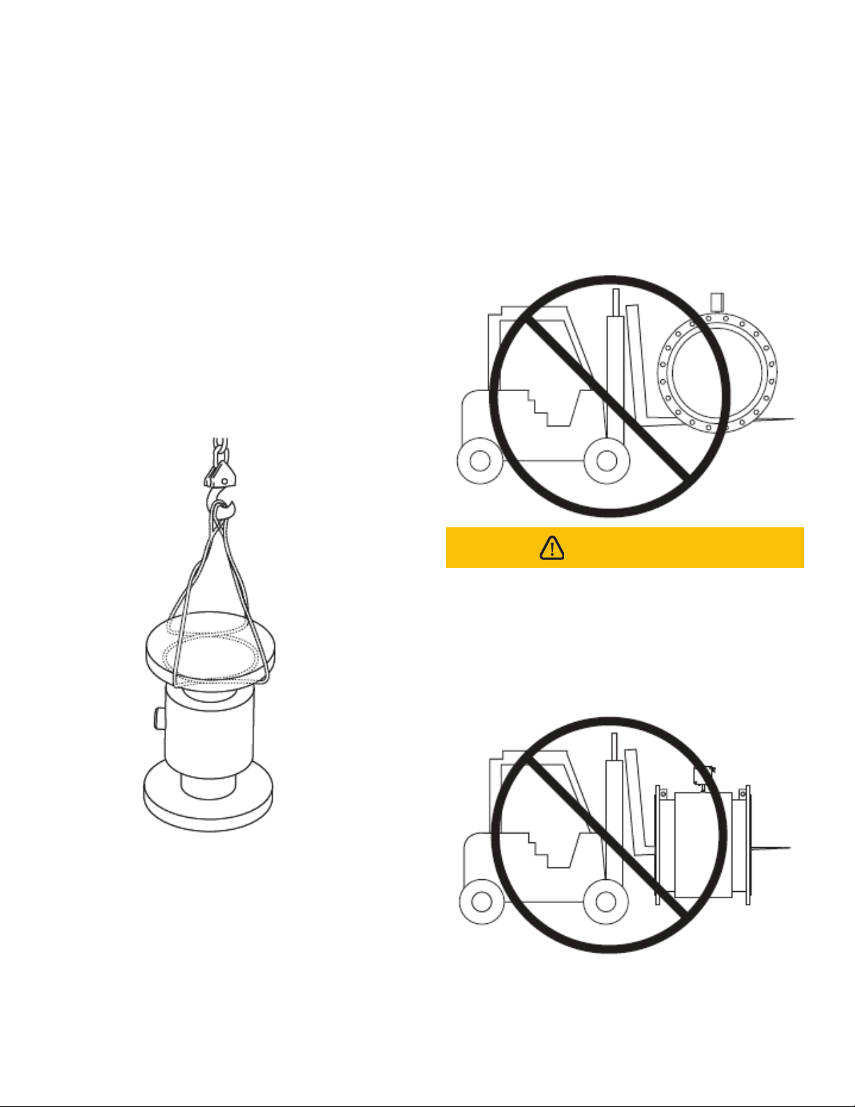
1.2 Unpacking and Inspection........................................4
2. Technical Data .................................................................. 5
3. Measurable Flow Ranges ............................................... 6
4. Model Selection................................................................ 7
5. Installation Considerations............................................. 8
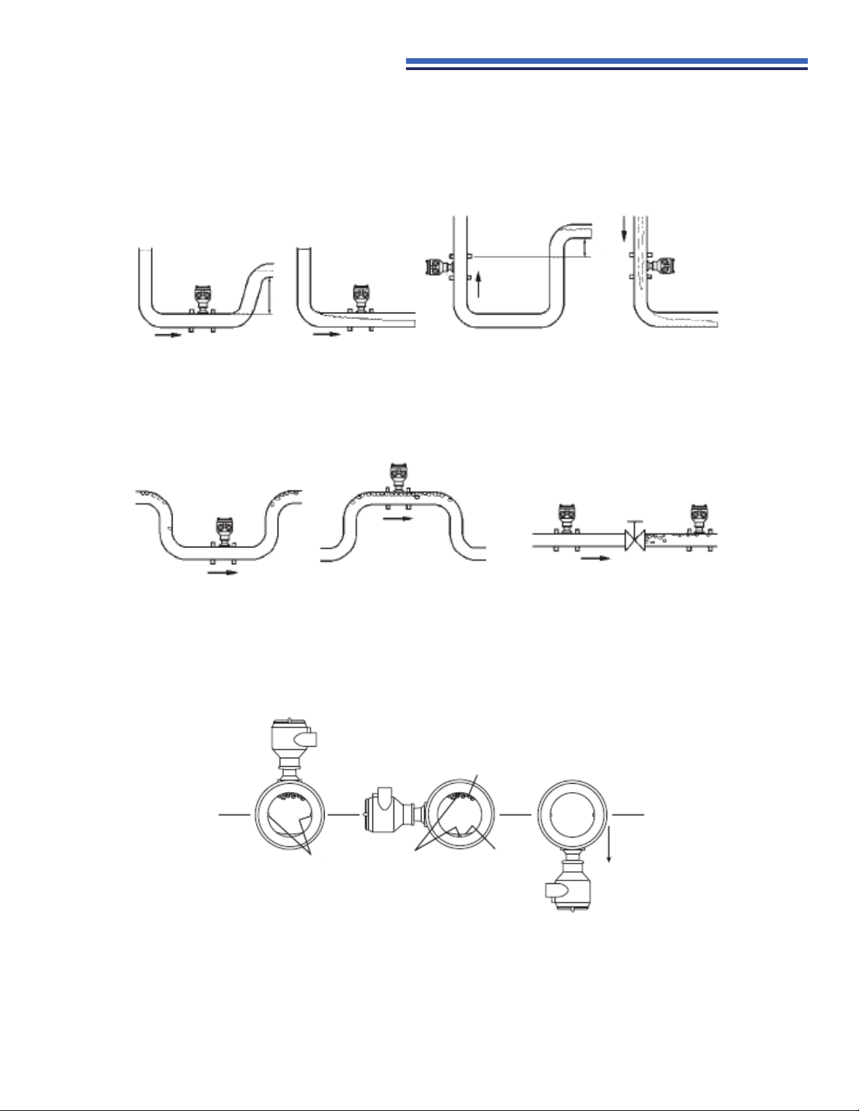
5.1 Mounting Positions......................................................8
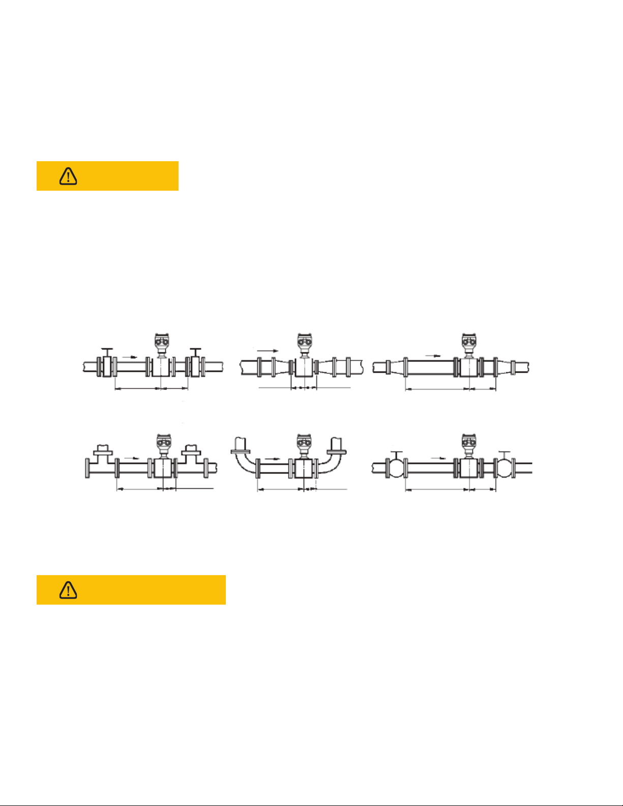
5.2 Required Lengths of Straight Runs ........................9
5.3 Grounding ......................................................................10
5.4 Connections ..................................................................10
6. Converter Connection..................................................... 13
6.1 Terminal Wiring and Marking (Compact Type)....13
6.2 Terminal Wiring and Marking (Remote Type) ......14
6.3 Connection Wire and Cable Characteristics
and Connection Requirements ...............................14
6.4 Output and Power Cord ............................................15
7. Setting Parameters .......................................................... 18
7.1 Flow Setup.....................................................................18
7.2 Alarm Setup...................................................................22
7.3 Output Setup.................................................................24
7.4 Sensor Setup.................................................................26
7.5 Communication Setup................................................27
7.6 Parameter Modification Tag......................................27
8. Instrument Display and Operation................................ 28
8.1 Key Function and Remote Control Function
(Compact Type) ............................................................28
8.2 Key Function and Remote Control Function
(Remote Type)...............................................................29
8.3 Function Selection Screen and Parameter
Setting Operation ........................................................31
9. Product Performance and Indicators ........................... 32
9.1 Basic Functions ............................................................32
9.2 Special Functions ........................................................32
9.3 Normal Working Conditions .....................................32
9.4 Connection Method with Sensor............................32
9.5 Sensor Matching Requirements..............................32
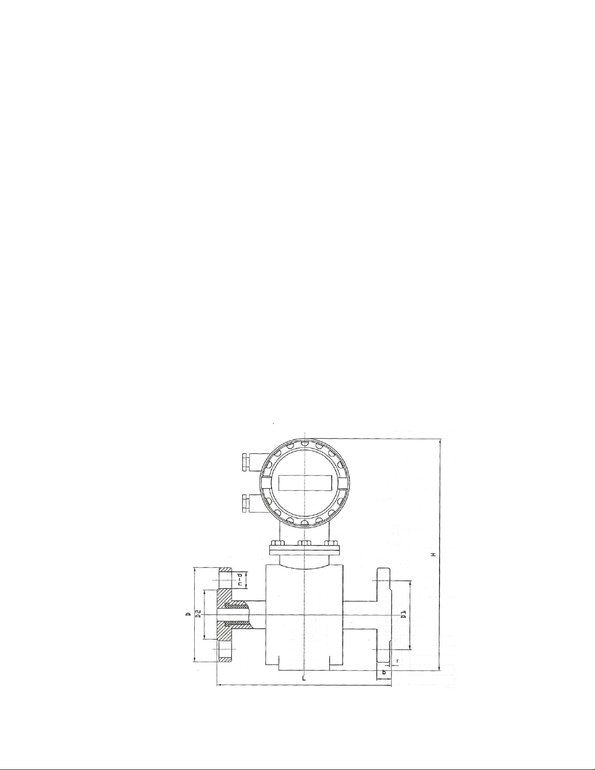
9.6 Installation Dimension Drawing...............................33
9.7 Measuring Accuracy...................................................34
9.8 Analog Current Output ..............................................35
9.9 Digital Frequency Output..........................................35
9.10 Digital Pulse Output ....................................................35
9.11 Alarm Output.................................................................35
9.12 Digital Communication Interface and
Communication Protocol...........................................35
9.13 Electrical Isolation........................................................36
9.14 Digital Output and Calculation ................................36
9.15 Analog Output and Calculation...............................38
10. Alarm Information ............................................................ 40
11. Troubleshooting ............................................................... 40
12. Storage ........................................................................ 41
Appendix I Non-linear Correction Function Description... 41
Appendix II List of Instrument Menus.................................... 43
Appendix III Passwords ............................................................. 46
Product Warranty ........................................................................ 47

3www.h2flow.net
1.1 Description
The FaraMag FM750 utilizes the electromagnetic principle to measure the flow volume of conductive liquids and slurry in
a closed pipe. This technology is widely used in power, oil and gas, chemical and petrochemical, coal, metallurgy, mineral,
paper, water, wastewater, food and beverage, pharmaceutical and other industries.
The FM750 is characterized by it’s high degree of accuracy and reliability. Setting of flow meter parameters is performed
using the keypad and intuitive display menu or using service software via a communication port.
The FM750 comprises of two basic components: 1) the Sensor, which includes the flow tube, isolating liner and measuring
electrodes, and 2) the Converter, which is the electronic device responsible for signal processing, flow calculation, display
and output signals.
The materials of construction of the wetted parts (liner and electrodes) should be appropriate for the specifications on the
intended type of service. Review of the compatibles consistent with the specifications is recommended.
All FaraMag™ FM750 electromagnetic flow meters are factory tested and calibrated. A calibration certificate is included in the
shipment of each meter.
WARNING
PLEASE BE AWARE THAN AN INDUCTION FLOW METER IS AN ELECTRONIC DEVICE; THE FOLLOWING
STEPS SHOULD BE PERFORMED BY A QUALIFIED ELECTRICIAN!
1. general information
This manual will assist you in installing, using and maintaining your flow meter. It is your responsibility to make sure that all
operators have access to adequate instructions about safe operating and maintenance procedures.
1. Use only fluids that are compatible with the housing
material and wetted components of your meter.
2. When measuring flammable liquids, observe precautions
against fire or explosion.
3. When handling hazardous liquids, always follow the
fluids manufacturer’s safety precautions.
4. When working in hazardous environments, always
exercise appropriate safety precautions.
5. During meter removal, fluids may spill. Follow the fluids
manufacturer’s safety precautions for clean up minor
spills.
6. When tightening the meter, use a wrench only on the
wrench flats.
7. For best results, calibrate the meter at least 1 time per
year.
For your safety, please review the major warnings and cautions below before operating your equipment.

4
www.h2flow.net
1.2 Unpacking and Inspection
Upon receipt, examine your meter for any visible damage. The meter is a precision measuring instrument and should be
handled with care. Remove the protective plugs and caps for a thorough inspection. If any items are damaged or missing,
please contact us immediately.
Make sure the flow meter model meets your specific needs. For your future reference, it might be useful to record the
information found on the nameplate in the manual, in case it becomes unreadable on the meter.
Do not lift the Sensor from the Converter housing, the
junction box, or the connecting cable. It is recommended
that larger size units are lifted using lifting lugs. Very
large meter sizes are packed and crated with the
meter laying on its side for shipping safety and stability
reasons. In order to lift the meter in a vertical position, it
is recommended that a sling rigged method is used - as
shown below.
If using a forklift, do not lift the detector from its body
between the flanges. The housing could be accidentally
dented and permanent damage could be caused to the
internal coil assemblies.
WARNING
Warning: NEVER introduce the forklift, chains, wire slings
or any other sharp object inside the flow tube for lifting
or handling purposes. This could permanently damage
the isolating liner and could render the meter inoperable.
Handling the meter in this manner will VOID the product
warranty.

5www.h2flow.net
2. technical data
This manual will assist you in installing, using and maintaining your flow meter. It is your responsibility to make sure that all
operators have access to adequate instructions about safe operating and maintenance procedures.
Main Power 120-240VAC 50Hz - 60Hz / 24-36VDC
Power Consumption <15W (and set with sensor supporting power consumption)
Display and Push Buttons English and Chinese display can display the instantaneous flow, total flow and percentage of flow as well as
alarm display, four soft-touch buttons, which are used for data set.
Accumulator Forward total quantity, reverse total quantity
Output Signal
Analog output Bi-directional, isolation 0-10mA / 4-20mA
Frequency
output
Forward and reverse flow output with frequency range set between 1 - 5000Hz. The external
voltage must be lower than 35V and the max output current is 50mA when the transistor is
turned on.
Alarm output
Two outputs from the collectors of photoelectric isolate transistors are for alarm signals.
The external voltage must be lower than 35V and the max output current is 250mA when
the transistor is turned on. Alarm status: Activates when the measured pipes are empty, the
excitation circuits are broken, or the volume of flow rate exceeds the value designed limits.
Pulse output
For pulse output in forward and reverse flow measurement, upper frequency of pulse output
can be up to 5000 CP/S relevant value of pulse is from 0.0001 to 1.0 M3/P. The width of
pulse can be set to 20ms or squired wave form automatically. The collector of transistor with
photoelectric is open circuited. The external voltage must be lower than 35V and maximum
output current is 250mA when the transistor is turned on.
Accuracy ±0.5% of the value displayed
Damping Time Constant Continuous variable from 0-100 s (90%) can be selected by group
Communication RS232, RS485 or HART Communication are optional, with lightning resistance
Power Failure An anti-failure clock is designed in the flow meter which can save the power failure records for 16 times (10
years)
Protection Grade NEMA 4 / IP65
Nominal Diameter 0.5” - 120” (DN15 - DN3000)
Nominal Pressure 0.6 - 4.0MPa
Output Signal Analog output, Frequency output, Alarm output, Pulse output
Liner Material Neoprene, Urethane Rubber, Polysilicone Rubber, PTFE, F46, PFA
Electrode Type General Type, scraper type, replaceable type
Electrode Material SUS316, Hastelloy B, Hastelloy C, Titanium, Tantalum, Platinum-iridium alloy, Stainless Steel covered with
Tungsten Carbide
Medium Temperature
Integrated Type -4°F - +158°F (-20°C - +70°C)
Remote Type
Neoprene & Polyurethane
Liner -4°F - +140°F (-20°C - +60°C)
PTFE Liner / PFA Liner / F46
Liner -40°F - +356°F (-40°C - +180°C)
Ambient Temperature -13°F - +140°F (-25°C - +60°C)
Ambient Humidity 5 - 100% RH (relative humidity)
Medium Electrical Conductivity ≥20us/cm
Measuring Range 1500:1, flow rate <15m/s
Structure Type Integral Type, Remote Type, Submersible Type, ex-proof Type
Connection Type Flange Type / Clamp Type (optional on certain models)
Protection Grade NEMA4 (IP65), NEMA 6 (IP67), NEMA 6P (IP68)
Product Standard JB/T 9248-1999 Electromagnetic Flowmeter

6
www.h2flow.net
3. measurable flow rate ranges
Flow rate Unit: Gal/h
Min. Max.
0.0281 42.0147
0.0497 74.6928
0.0779 116.7076
1.9900 298.7714
0.3112 466.8306
0.5261 788.9435
0.7969 1195.0859
1.2446 1867.3217
2.8011 4201.4742
4.9796 7469.2871
7.7803 11670.7614
11.2039 16805.8966
15.2497 22874.6926
19.9181 29877.1491
25.2090 37813.2670
31.1221 46683.0457
44.8158 67223.5859
60.9990 91498.7697
79.6725 119508.5972
100.8353 151253.0686
124.4879 186732.1832
179.2627 268894.3440
243.9967 365995.0791
318.6896 478034.3891
403.3413 605012.2739
497.9523 746928.7331
602.5226 903546.0122
717.0517 1075577.3760
841.5388 1262308.0460
AVAILABLE UPON REQUEST
Flow rate Unit: m3/h
Min. Max.
0.0064 9.5426
0.0113 16.9646
0.0177 26.5072
0.4520 67.8584
0.0707 106.0288
0.1195 179.1886
0.1810 271.4336
0.2827 424.1150
0.6362 954.2588
1.1310 1696.4600
1.7671 2650.7188
2.5447 3817.0351
3.4636 5195.4089
4.5239 6785.8401
5.7256 8588.3289
7.0686 10602.8752
10.1788 15268.1403
13.8544 20781.6354
18.0956 27143.3605
22.9022 34353.3157
28.2743 42411.5008
40.7150 61072.5612
55.4177 83126.5416
72.3823 108573.4421
91.6088 137413.2627
113.0973 169646.0033
136.8478 205217.6640
162.8602 244290.2448
191.1343 286701.4020
AVAILABLE UPON REQUEST
Inch DN mm
0.5 15
0.75 20
1 25
1.5 40
2 50
2.5 65
3 80
4 100
6 150
8 200
10 250
12 300
14 350
16 400
18 450
20 500
24 600
28 700
32 800
36 900
40 1000
48 1200
56 1400
64 1600
72 1800
80 2000
88 2200
96 2400
104 2600
112 2800
120 3000

7www.h2flow.net
4. model selection
Model Ordering Code Description
FM750 A B C D E F G H I
Sensor Material
CS Carbon Steel
SS 316 Stainless Steel
Diameter:
A005 Minimum ANSI diameter (0.5”)...
A120 Maximum ANSI diameter (120”)
D15 Minimum DN diameter (DN15)...
D3000 Maximum DN diameter (DN3000)
Liner Material:
1 PTFE (F4); 0.5” - 40”
2 Neoprene; 2” - 120”
3 Polyurethane; 0.5” - 24”
4 F46; 0.5” - 12”
5 PFA; 0.5” - 10”
Electrode Material:
1 Stainless Steel (316L)
2 HB (Hastelloy B)
3 HC Hastelloy C)
4 Ti (Titanium)
5 Platinum iridium
6Ta
7 Stainless Steel Tungsten Carbide
Housing Protection:
1 NEMA 4 / IP65
2NEMA 6P / IP68 + NEMA 4 / IP65 (Sensor NEMA 6P / IP68
+ Converter NEMA 4 / IP65)
Mounting Accessories:
0 None
1 Grounding Ring
2 Mounting Flange
3 Scraper Electrode
Structure:
ER Remote Type
EC Compact Type
*Standard cable length is 10 meters for remote type. Cable length is customizable.
Power Supply:
1 120VAC-230VAC
2 11-40VDC
3 11-40VDC with 120VAC-230VAC converter (UL listed)
4 3.6V Lithium Battery
Converter Model:
MA Pulse+4-20mA, RS485
MB Pulse+4-20mA, RS485, HART
MC Pulse+4-20mA, RS485, Profibus DP
MD Pulse+4-20mA, RS232
ME GPRS Wireless Communication

8
www.h2flow.net
5. installation considerations
5.1 Mounting Positions
• Pipes must be fully filled with liquid. It is essential that pipes remain fully filled at all times, otherwise flow rate indications
may be aected and measurement errors may occur.
(Correct)
Fig. 5.1 Mounting Positions
h
(Incorrect)
(Correct) (Incorrect)
h
h>0
h>0
• Avoid air bubbles. If air bubbles enter a measurement pipe, flow rate indications may be aected and measurement
errors may be caused.
Fig. 5.2 Avoiding Air Bubbles
(Correct)
(Incorrect)
(Correct) (Incorrect)
Valve
• If the electrodes are vertical to the ground, air bubbles near the top or precipitates at the bottom may cause
measurement error. Ensure that the terminal box is mounted above the piping to prevent water from entering them.
Fig. 5.3 Mounting Orientation
(Correct) (Incorrect)
Water can seep into
the terminal box
Air Bubbles
Electrodes Electrodes Precipitate
• Avoid all pipe locations where the flow is pulsating, such as in the outlet side of piston or diaphragm pumps.
• Avoid locations near equipment producing electrical interference , such as electric motors, transformers, variable
frequency drives, etc.

9www.h2flow.net
• Install the meter with enough room for future access for maintenance purposes.
• The magnetic meter isolating liner, whether it is PTFE or Rubber, is not intended to be used as gasket material. Standard
gaskets (not provided) should be installed to ensure a proper hydraulic seal. When installing the gaskets, make sure they
are properly centered to avoid flow restriction or turbulence. Do not use graphite or any electrically conductive sealing
compound to hold the gaskets in place during installation, as this could aect the reading accuracy of the measuring
signal.
WARNING Precaution for direct sunshine and rain when the meter is installed outside:
5.2 Required Lengths of Straight Runs
For optimum accuracy and performance, it is required that sucient inlet and outlet straight pipe runs are provided. An
equivalent to 3 diameters of straight pipe is required on the inlet side, and 2 diameters on the outlet side. There are no
special requirements for standard concentric pipe reducers. See Fig.5.4 for required straight runs when there is an altering
device.
Fig. 5.4 Required Straight Runs
Gate Valve
Fully Open Reducer Pipe Expander Pipe
D = Flowtube Size
5D or more 2D or more 0 is allowable 0 is allowable 10D or more 2D or more
Tee 90-degree bent Various Valves
5D or more 0 is allowable 5D or more 0 is allowable 10D or more 2D or more
SPECIAL NOTICE
When the meter contains removable cover plates, leave them installed unless accessory modules specify removal. Don’t
remove the cover plates when the meter is powered, or electrical shock and explosion hazard may occur.

10
www.h2flow.net
5.3 Grounding
In this section, the term “grounding” will be defined as: the arrangement of process wetted metal materials (piping, ground
rings, ground electrodes), cabling (ground straps, ground wires), and connections to stable references (often, but not always
earth ground) required to achieve satisfactory operation of a magnetic flow meter. As such, it applies to the instrumentation
aspect of grounding, rather than to “safety grounding”.
Proper installation and grounding of the magnetic flow meter is important for accurate and reliable measurement
performance. Stray AC or DC currents through the fluid or instrument can produce noise signals that may in turn interfere with
the relatively low flow signals generated in today’s modern pulsed DC mag meter.
H2flow Controls provides a variety of elements (ground straps, ground electrodes, ground rings) and directions for the
standard grounding of the mag meter.
Applications exist in which the user cannot or should not make use of the traditional grounding connection to adjacent
piping and to earth ground. These flow measurement applications are frequently encountered in electrolytic processes.
In this case, the fluid passing through the mag meter flow tube may potentially be at significantly higher or lower than
earth ground, and a connection to earth ground may be detrimental to the performance and even the reliability of the
mag meter. These applications are typically compounded by the use of non-conductive or lined pipe and may feature
acid or caustic flows which may necessitate the use of expensive wetted electrodes and grounding materials such as
titanium, platinum, or tantalum.
5.4 Connections
Use a gasket between the meter flange and mating flange. Determine the material of the gasket based on the
operating conditions and type of fluid.
Note: Do not over tighten the flange bolts. This may cause the gasket to be compressed into the flow stream and may
decrease the accuracy of the meter.
Installation Dimensions: Refer to the following Figures and Tables.
Fig. 5.5 Drawings for Integrated Electromagnetic Flow Meter

11 www.h2flow.net
Fig. 5.6 Drawings for Remote Electromagnetic Flow Meter
Flange: DIN PN16
Diameter DN L H H1 D D1 D2 n x d
10 160 360 220 90 60 41 4 x 14
15 160 360 220 95 65 45 4 x 14
20 165 360 220 105 75 58 4 x 14
25 200 360 220 115 85 68 4 x 14
32 200 370 235 140 100 78 4 x 18
40 200 370 235 150 110 88 4 x 18
50 200 358 242 165 125 102 4 x 18
65 250 400 256 185 145 122 4 x 18
80 250 415 275 200 160 138 8 x 18
100 250 435 295 220 180 158 8 x 18
125 250 465 325 250 210 188 8 x 18
150 300 497 355 285 240 212 8 x 22
200 350 550 410 340 295 268 12 x 22
250 450 610 488 405 355 320 12 x 22
300 500 660 520 460 410 375 12 x 22

12
www.h2flow.net
Flange: JIS 10K
Diameter DN L H H1 D D1 D2 n x d
10 160 360 220 90 64 46 4 x 15
15 160 360 220 95 70 52 4 x 15
20 165 360 220 100 75 58 4 x 15
25 200 360 220 125 90 70 4 x 19
32 200 370 235 135 100 76 4 x 19
40 200 370 235 140 105 85 4 x 19
50 200 358 242 155 120 100 4 x 19
65 250 400 256 175 140 120 4 x 19
80 250 415 275 185 150 130 8 x 19
100 250 435 295 210 175 155 8 x 19
125 250 465 325 250 210 185 8 x 23
150 300 497 355 280 240 215 8 x 23
200 350 550 410 330 290 265 12 x 23
250 450 610 488 400 355 325 12 x 25
300 500 660 520 415 400 370 16 x 25
Flange: ANSI 150#
Diameter
(inches) L H H1 D D1 D2 n x d
0.5 160 360 220 90 60 40 4 x 15
0.75 165 360 220 98 70 43 4 x 15
1200 360 220 108 79.5 51 4 x 15
1.5 200 370 235 127 98.5 73 4 x 15
2200 385 242 152 120.5 92 4 x 19
2.5 250 400 256 178 139.5 105 4 x 19
3250 415 275 190 152.5 127 4 x 19
4250 435 295 229 190.5 157 8 x 19
5250 465 325 254 216 186 8 x 23
6300 497 355 279 241.5 216 8 x 23
8350 550 410 343 298.5 270 8 x 23
10 450 610 488 406 362 324 12 x 25
12 500 660 520 483 432 381 12 x 25

13 www.h2flow.net
6. converter connection
6.1 Terminal Wiring and Marking (Compact Type)
Fig.6.1 Compact-Type Terminal Diagram
TERMINAL BLOCK
Terminal Description
DOUT - Alarm Output Ground
DOUT + Alarm Output Positive
POUT - Pulse/Frequency Output negative
POUT + Pulse/Frequency Output positive
4-20mA + 4-20mA positive
4-20mA - 4-20mA negative
RS485 + Communication input (RS485A)
RS485 - Communication input (RS485B)
N220VAC (24VDC negative) power input
L220VAC (24VDC positive) power input
NOTE: May be supplied as either 220VAC or
24VDC depending on customer order

14
www.h2flow.net
6.2 Terminal Wiring and Marking (Remote Type)
TERMINAL BLOCKS
Terminal Description
LN+ Power Input
LN- Power Input
F/P- Pulse/Frequency Output Ground
F/P+ Pulse/Frequency Output Positive
DOA- (DO-) Alarm Output Ground
DOA+ (DO+) Alarm Output Ground
DOB- Reservation
DOB+ Reservation
DIN- Reservation
DIN+ Reservation
TRX+ Communication Input (RS485-A)
TRX- Communication Input (RS485-B)
IOUT-(IO-) Current Output Ground
IOUT+(IO+) Current Output Positive
EXT+ Excitation Current Positive
EXT- Excitation Current Negative
SIG+ Signal 1
SGND Signal Ground
SIG- Signal 2
DRS+ Excitation Shield Positive
MTDR Excitation Shield Ground
DRS- Excitation Shield Negative
6.3 Connection Wire and Cable Characteristics and Connection Requirements
6.3.1 Flow Signal Wire
This converter provides equipotential excitation shielding signal output voltage to reduce the influence
of the distributed capacitance of the cable transmission on the current signal measurement. When the
measured conductivity is less than or long-distance transmission, dual-core, dual-shielded signal cables
with equipotential shielding can be used. For example, STT3200 dedicated cable or BTS type triple shielded
signal cable.
6.3.2 Excitation Current Wire
The excitation current line adopts a two-core insulated rubber flexible cable, and the recommended model is
RVVP2*0.3mm. The length of the excitation current line is the same as the length of the signal cable. When
using STT3200 dedicated cable, the excitation cable and signal cable are combined into one.
Fig.6.2 Remote-Type Terminal Diagram

15 www.h2flow.net
6.3.3 Grounding Requirements for Converter Installation
The ground terminal of the converter housing should be connected to the earth with a grounding copper
wire not less than 1.6mm. The grounding resistance from the converter case to the ground should be less
than 10.
First cut the Φ20 copper tube into a length of 1700mm (it can be lengthened as needed) to make ground nail
buried 1500mm (NOTE: when burying the ground nail, sprinkle a layer of broken wood carbon at the tip of
the ground nail, then pour salt water). Next, weld the 4mm purple copper wire to the ground nail, and finally
connect the ground wire to the sensor flange, ground ring, and pipe flange, as shown in Fig.6.3.
NOTE: Stainless Steel materials are required to fix the ground screw, spring washer, and flat washer.
Converter
Ground ring Gasket
Ripe flange
Sensor flange
Sensor flange
Ripe flange
Sensor
Ground ringGasket
Screw Screw nut
Spring washers Flat washers 4mm ground wire
Welding point
ground
charcoal
1500mm
Fig.6.3 Converter grounding diagram
6.4 Output and Power Cord
All output and power cables are prepared by the user according to the actual situation. Please pay attention to meet the
requirements of the load current. The external power supply and load for pulse, current and alarm output are shown in Figure
6.4.1 through 6.4.3. When using an inductive load, a freewheeling diode should be added as shown in the diagram.
Fig.6.4.1 Power supply within 4-20mA (current and pulse are not isolated)
Converter
User System
Signal Input
COMIO-
IO+

16
www.h2flow.net
6.4.1 Pulse Output Wiring
Fig.6.4.2a Power Supply connected to electronic counter (Compact Type)
Converter Terminal
PO-
PO+
DC Power Flow Cumulant
Fig.6.4.2c Power Supply connected to electronic counter (Remote Type)
Converter Terminal
F/P-
F/P+
DC Power Flow Cumulant
Converter Terminal
PO-
Flow Cumulant
Fig.6.4.2b Inner Power Supply connected to electric counter (Compact Type)
PO+

17 www.h2flow.net
6.4.3 Alarm Output Wiring
DO+ DO-
Converter Terminal
Upper/Lower Limit Alarm
DC Power
Fig.6.4.3 Alarm output wiring
6.4.4 Connection of OC Gate
Fig.6.4.4 Connection of OC Gate
(Compact-Type)
PO+
Meter Inside
Meter Outside
PO-
DO+
DO-
Fig.6.4.4 Connection of OC Gate
(Remote-Type)
F/P+
Meter Inside
Meter Outside
F/P-
DOA+
DOA-

18
www.h2flow.net
7. setting parameters
7.1 Flow Setup
7.1.1 Flow Units
Select the desired unit of measurement in the parameters. Choose from the following available options:
L/s, L/m, L/h, m3/s, m3/m, m3/h, uk/s, uk/m, uk/h, us/s, us/m, us/h, kg/s, kg/m, kg/h, t/s, t/m, t/h. The user
can select an appropriate flow display according to the process requirements or usage habits.
7.1.2 Flow Accumulation Unit
The converter display is a 9-digit counter, and the maximum allowable count value is 999999999. The total
unit used is L, m3, ukg, usg, kg, t (liters, cubic meters, British gallons, US gallons, kilograms, tons). This unit is
automatically set to be consistent with the flow unit. When the flow unit is L/h, L/m, L/s, the integration unit is
L. When the flow unit is m/h, m/m, m/s, the integration unit is m. When the flow unit is uk/s, uk/m, uk/h, the
integration unit is kg/s. When the flow unit is kg/s, kg/m, kg/h, the integration unit is kg. When the flow unit is
t/s, t/m, t/h, the integration unit is t.
Flow Accumulation Equivalent: 0.001 L, 0.010 L, 0.100 L, 1.000 L
0.001m, 0.010 m, 0.100 m, 1.000 m
0.001 ukg, 0.010 ukg, 0.100 ukg, 1.000 ukg
0.001 usg, 0.010 usg, 0.100 usg, 1.000 usg
0.001kg, 0.010 kg, 0.100kg, 1.000kg
0.001t, 0.010t, 0.100t, 1.000t
7.1.3 Reverse Output Allow
When the reverse output permission parameter is set in the “prohibited” state, as long as the fluid flows, the
converter will output pulses and currents according to the flow value, and the terminals DO+ and DO- output
high levels.
When the reverse output allowable parameter is set to “Allow”, if the fluid flows in the reverse direction, the
converter flow rate is displayed normally, the output pulse is “0”, the current output is signal “0” (4mA), the
instantaneous flow rate is displayed as 0, and the terminal DO+ and DO- output high level.
When the reverse output allowable parameter is set to “allowed output”, if the fluid flows in the reverse
direction, the converter flow rate is displayed normally, the output pulse is “0”, the current output is signal “0”
(4mA), and the instantaneous flow rate is displayed as 0. Terminal DO+ and DO- output low level Vil.
7.1.4 Reverse Output Allow
The “Meter Measure Range” setting is used to determine the upper limit flow value. The lower limit flow
value of the meter is automatically set to “0”.
Therefore, the meter range setting determines the meter measure range, and also determines the
corresponding relationship between the meter percentage display, meter frequency output, meter current
output and flow rate:
• Percentage display value of the meter = (measured flow value / measure range of
the meter) * 100%;
• Instrument frequency output value = (measured flow value / measure range of the
meter) * frequency full range value;
• Instrument current output value = (measured flow value / measure range of the meter) *
current full-scale value + zero point;
The pulse output value of the instrument is not affected by the instrument measure range setting.

19 www.h2flow.net
7.1.5 Measuring Damping Time
Filtering time, or long measurement damping time can improve the stability of the meter flow display and
the stability of the output signal, which is suitable for the total accumulated pulsating flow measurement. The
short measurement damping time represents a quick measurement response speed, which is suitable for
production process control. The measurement damping time is divided into 1S, 2S, 3S, 4S, 6S, 8S, 10S, 15S,
30S, 60S, and can choose the setting mode.
7.1.6 Analog Output Damping
The current filtering time, or long analog output damping can improve the stability of the 4-20mA output
signal. The short analog output damping is manifested in the fast measurement of the response speed of
4-20 mA. Analog output damping: 5S, 10S, 20S, 50S, 80S, 150S, 250S, and can choose the setting mode.
7.1.7 Peak Suppression Allow
For pulp, mud and other slurry flow measurement, solid particles in the fluid friction or impact measurement
electrode, will cause a “peak pseudo-signal “. To overcome such pseudo-signal, the converter design has
a peak suppression function. User set peak fluctuation flow value and peak width time. The converter will
suppress the peak pseudo-signal in accordance with the set value to minimize the flow fluctuation.
The parameter “peak suppression permission” has two functions :1) the parameter is set to “allow” to start the
peak suppression function. 2) the parameter is set to “Not-allowed “. Turn off the peak suppression function
and turn on the noise sensitivity test.
7.1.8 Peak Suppression Range
This parameter has two functions:
1. When the “peak suppression allowed” parameter is set to allow, the value confirms
the peak suppression start value, which is used to set the velocity fluctuation value to
suppress the peak pseudo signal. If the current velocity fluctuation is higher than the
starting value, it is considered that the change is caused by the peak pseudo signal,
and the system cuts and displays the PSM alarm. When the velocity fluctuation is lower
than the initial value, it is considered that the change is caused by the real velocity
change, and the system recognizes that the velocity change is measured.
2. When the “peak suppression allowed” parameter is set to forbidden, the value
determines the sensitivity test for noise. If the “FST” display appears frequently, it is
recommended to increase the peak suppression range.
7.1.9 Peak Suppression Time
This parameter selects the peak width time to suppress peak pseudo-signal. This is displayed in units of
seconds.

20
www.h2flow.net
Unattended measured variable
t-Blanking time Time
Allowable
Range
+
-
t t t
Fig.7.1.6 Eliminate gross error noise with peak suppression range technology
Time
Indicates the flow with the filtering time constant as a
percentage.
For abnormal conditions, such as bubbles in the water, in order to prevent the flow from returning to “zero”,
the converter has an abnormal suppression function in the software and hardware. When the converter
detects an abnormal condition, the converter will display an ABN abnormal alarm for abnormalities within a
period of time. The flow rate is suppressed to prevent the flow rate from returning to “zero” and suppress
flow fluctuations to a minimum. This parameter is used for the length of abnormal suppression time, which
can be selected from 0 to 99s. When 0s is selected, this function will be canceled.
7.1.10 Flow Direction Options
If user believes that the fluid direction during commissioning is inconsistent with the design, the connection
of the excitation wire or signal wire does not need to be changed. Simply adjust the flow direction setting
within the parameters.
Table of contents
Other H2flow Measuring Instrument manuals
Popular Measuring Instrument manuals by other brands

Rotronic
Rotronic HygroClip Digital quick start guide

Omntec
Omntec PROTEUS B installation manual

Dexcom
Dexcom G5 Mobile Getting started guide

Carlson
Carlson Boretrak2 user manual

Shimpo Instruments
Shimpo Instruments PT-110 Operation manuals

GE Wiring Devices & Specialty Products
GE Wiring Devices & Specialty Products GE5805WS6 user manual