H3C S5500-SI Series User manual

Operation Manual – VLAN
H3C S5500-SI Series Ethernet Switches Table of Contents
i
Table of Contents
Chapter 1 VLAN Configuration ....................................................................................................1-1
1.1 VLAN Overview..................................................................................................................1-1
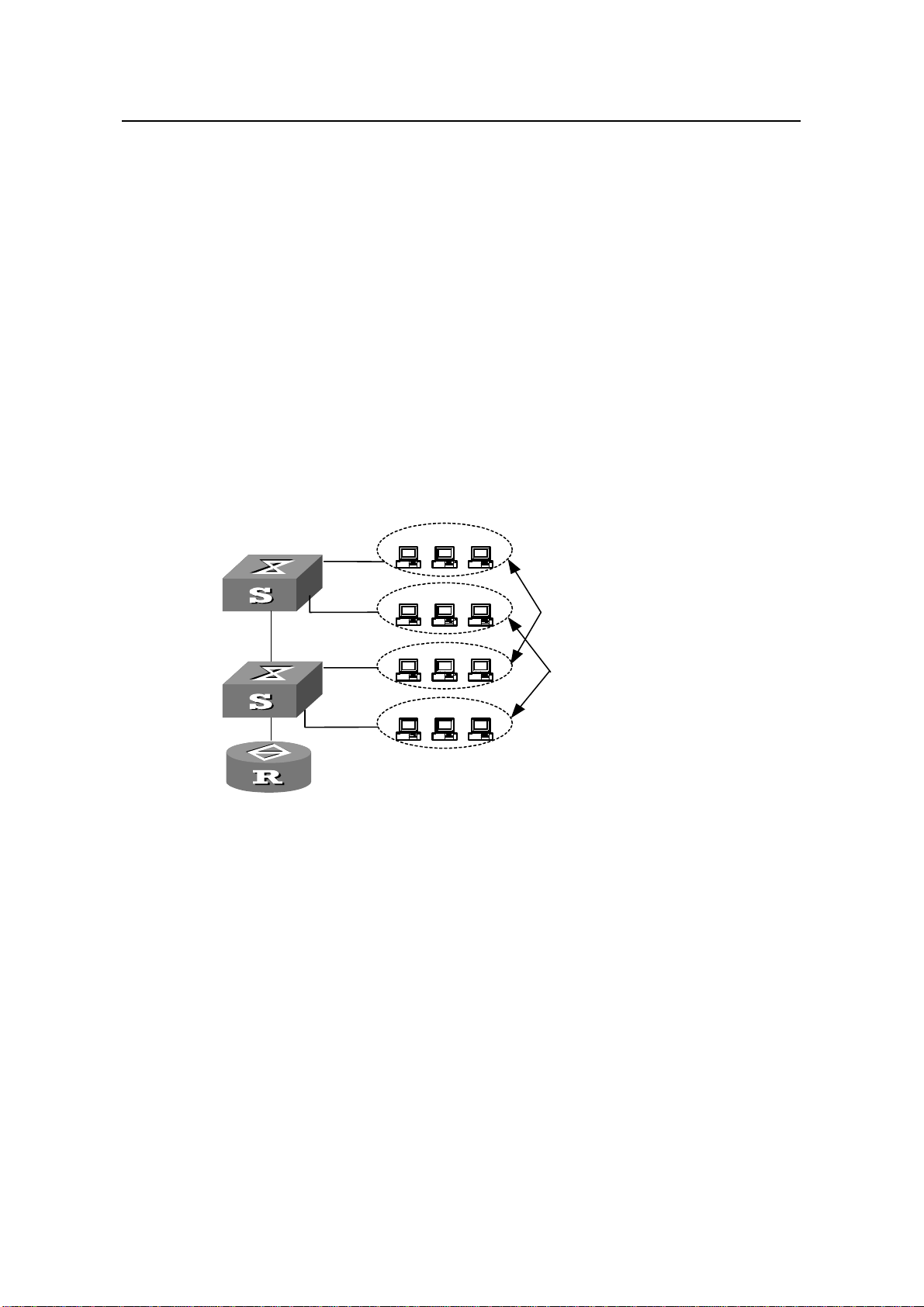
1.1.1 Introduction to VLAN...............................................................................................1-1
1.1.2 VLAN Classification.................................................................................................1-2
1.2 Basic VLAN Configuration................................................................................................. 1-2
1.3 Basic VLAN Interface Configuration..................................................................................1-2
1.4 Port-Based VLAN Configuration........................................................................................1-3
1.4.1 Introduction of Port-Based VLAN............................................................................1-3
1.4.2 Configuring an Access Port-Based VLAN...............................................................1-5
1.4.3 Configuring a Trunk Port-Based VLAN...................................................................1-6
1.4.4 Configuring a Hybrid Port-Based VLAN..................................................................1-7
1.5 Displaying VLAN Configuration .........................................................................................1-8
1.6 VLAN Configuration Example............................................................................................1-9
1.6.1 Network Requirements............................................................................................1-9
1.6.2 Network Diagram.....................................................................................................1-9
1.6.3 Configuration Procedure.........................................................................................1-9
Chapter 2 Voice VLAN Configuration.......................................................................................... 2-1
2.1 Voice VLAN Overview .......................................................................................................2-1
2.1.1 Automatic and Manual Voice VLAN Modes............................................................2-1
2.1.2 Security and Ordinary Voice VLAN Modes............................................................. 2-4
2.2 Voice VLAN Configuration................................................................................................. 2-4
2.2.1 Configuration Prerequisites.....................................................................................2-4
2.2.2 Configuring Voice VLAN in Automatic Mode ..........................................................2-5
2.2.3 Configuring Voice VLAN in Manual Mode...............................................................2-6
2.3 Displaying Voice VLAN...................................................................................................... 2-7
2.4 Voice VLAN Configuration Example..................................................................................2-7
2.4.1 Voice VLAN Configuration Example (Automatic Mode)..........................................2-7
2.4.2 Voice VLAN Configuration Example (Manual Mode)..............................................2-9
Chapter 3 GVRP Configuration....................................................................................................3-1
3.1 Introduction to GARP......................................................................................................... 3-1
3.1.1 Introduction to GARP..............................................................................................3-1
3.1.2 Introduction to GVRP..............................................................................................3-3
3.1.3 Protocols and Standards......................................................................................... 3-4
3.2 Configuring GVRP.............................................................................................................3-4
3.2.1 Configuring GVRP...................................................................................................3-4
3.2.2 Setting GARP Timer................................................................................................3-5
3.3 Displaying and Maintaining GARP/GVRP.........................................................................3-6

Operation Manual – VLAN
H3C S5500-SI Series Ethernet Switches Table of Contents
ii
3.4 GVRP Configuration Example........................................................................................... 3-7
3.4.1 Example 1 ...............................................................................................................3-7
3.4.2 Example 2 ...............................................................................................................3-8
3.4.3 Example 3 ...............................................................................................................3-9

Operation Manual – VLAN
H3C S5500-SI Series Ethernet Switches Chapter 1 VLAN Configuration
1-1
Chapter 1 VLAN Configuration
1.1 VLAN Overview
1.1.1 Introduction to VLAN
The virtual local area network (VLAN) technology is developed for switches to control
broadcast operations in LANs.
By creating VLANs in a physical LAN, you can divide the LAN into multiple logical LANs,
each of which has a broadcast domain of its own. Hosts in the same VLAN
communicate with each other as if they are in a LAN. However, hosts in different VLANs
cannot communicate with each other directly. In this way, a broadcast frame is confined
within one VLAN, as shown in Figure 1-1.
VLAN A
VLAN B
VLAN A
VLAN B
VLAN A
VLAN B
LAN Switch
LAN Switch
Router
Figure 1-1 A VLAN implementation
A VLAN can span across multiple switches, or even routers. This enables hosts in a
VLAN to be dispersed in a more loose way. That is, hosts in a VLAN can belong to
different physical network segments.
VLAN enjoys the following advantages.
zBroadcasts are confined to VLANs. This decreases bandwidth utilization and
improves network performance.
zNetwork security is improved. Packets of different VLANs are isolated during
transmission. That is, hosts in different VLANs cannot communicate with each
other directly. To enable communications between different VLANs, network
devices operating on Layer 3 (such as routers or Layer 3 switches) are needed.

Operation Manual – VLAN
H3C S5500-SI Series Ethernet Switches Chapter 1 VLAN Configuration
1-2
zConfiguration workload is reduced. VLAN can be used to group specific hosts.
When the physical position of a host changes, no additional network configuration
is required if the host still belongs to the same VLAN.
1.1.2 VLAN Classification
Depending on how VLANs are established, VLANs fall into the following six categories:
zPort-based VLAN
zMAC-based VLAN
zProtocol-based VLAN
zIP sub network-based VLAN
zPolicy-based VLAN
zOther VLAN
H3C S5500-SI Series Ethernet Switch supports the port-based VLAN. This chapter will
focus on the port-based VLAN.
1.2 Basic VLAN Configuration
Table 1-1 Basic VLAN configuration
To do… Use the command… Remarks
Enter system view system-view —
Create VLANs in bulk vlan { vlan-id1 to
vlan-id2 | all } Optional
Create a VLAN and
enter VLAN view vlan vlan-id
Required
If the specified VLAN does not
exist, this command will first
create the VLAN, and then
enter VLAN view.
Specify the description
string of the VLAN description text
Optional
By default, the description
string of a VLAN is its VLAN
ID, such as “VLAN 0001”.
1.3 Basic VLAN Interface Configuration
VLAN interface is a virtual interface in Layer 3 mode, and mainly used in realizing the
Layer 3 connectivity between different VLANs.

Operation Manual – VLAN
H3C S5500-SI Series Ethernet Switches Chapter 1 VLAN Configuration
1-3
Table 1-2 Configure a VLAN interface
To do… Use the command… Remarks
Enter system view system-view —
Create a VLAN interface
and enter VLAN interface
view
interface vlan-interface
vlan-interface-id
Required
If the specified VLAN
interface does not exist,
this command will create
it first and then enter
VLAN interface view.
Configure IP address of
VLAN interface
ip address ip-address
{ mask |mask-length }
[ sub ]
Optional
By default, no IP address
is configured for a VLAN
interface
Specify the description
string for the current
VLAN interface description text
Optional
By default, the description
string of a VLAN interface
is the name of the VLAN
interface, such as
“Vlan-interface1
interface”.
Enable the VLAN
Interface undo shutdown
Optional
By default, if all the ports
under the VLAN interface
are down, the VLAN
interface is down; if one or
more ports under the
VLAN interface are up,
the VLAN interface is up.
Note:
Before creating a VLAN interface, the corresponding VLAN must exist. Otherwise, you
cannot create the VLAN interface successfully.
1.4 Port-Based VLAN Configuration
1.4.1 Introduction of Port-Based VLAN
Port-based VLAN is the simplest and most effective VLAN division method. It defines
its VLAN members according to the ports of a switch. After a specified port is added into
a specified VLAN, the port can forward the packets of the specified VLAN.

Operation Manual – VLAN
H3C S5500-SI Series Ethernet Switches Chapter 1 VLAN Configuration
1-4
I. Link Type of an Ethernet Port
Depending on how a port processes VLAN tags when it forwards packets, the link type
of the port can be one of the following three types:
zAccess. An access port belongs to only one VLAN; it strips VLAN tags when
sending the packets of the VLAN. An access port is generally used to connect a
user device.
zTrunk. A trunk port can belong to more than one VLAN and receives/sends the
packets of multiple VLANs; it is generally used to connect a switch.
zHybrid. A hybrid port can also belong to more than one VLAN and receives/sends
the packets of multiple VLANs; it is used to connect a switch or a user device.
The difference between the hybrid port and the trunk port is that:
zA hybrid port allows the packets from multiple VLANs to be sent without tags.
zA trunk port only allows the packets from the default VLAN to be sent without tags.
II. Default VLAN
You can configure a VLAN for a port. In additional, you can also configure a default
VLAN for the port. By default, the default VLAN of all the ports is VLAN 1. But you can
configure it as needed.
zThe default VLAN of an access port is the VLAN the access port belongs to and
cannot be configured.
zBoth of the trunk port and hybrid port allow multiple VLANs to pass through. You
can configure the default VLAN for them.
zAfter you delete the default VLAN of a port through the undo vlan command, for
an access port, its default VLAN restore to VLAN 1; for a trunk or a hybrid port, its
default VLAN configuration remain unchanged, that is, a trunk port or hybrid port
can use the presently nonexistent VLAN as the default VLAN.
Note:
For ports of a voice VLAN in automatic mode, you cannot configure the voice VLAN as
the default VLAN of the ports. If you do so, the system will prompt that you cannot
perform the configuration. For information about the voice VLAN, refer to Chapter 2
Voice VLAN Configuration.
The way by which a port processes incoming and outgoing packets depends on the link
type and default VLAN configured on it. Refer to the following table for details:

Operation Manual – VLAN
H3C S5500-SI Series Ethernet Switches Chapter 1 VLAN Configuration
1-5
Table 1-3 Incoming and outgoing packets
Incoming packet
Port type If no tag is
carried in the
packet
If a tag is carried in
the packet
Outgoing packet
Access
port
zReceive the packet
when the VLAN ID
(recorded in the
tag) is the same
with the default
VLAN ID.
zDrop the packet
when the VLAN ID
is different with the
default VLAN ID.
Remove the tag and send
the packet directly for the
VLAN ID is just the default
VLAN ID.
Trunk port
zWhen the VLAN ID is
the same with the
default VLAN ID,
remove the tag of the
packet first and then
send the packet.
zWhen the VLAN ID is
different with the
default VLAN ID but is
allowed on the port,
keep the original tag
and send the packet.
Hybrid
port
Encapsulate
the default
VLAN tag to the
packet
zReceive the packet
when the VLAN ID
(recorded in the
tag) is the same
with the default
VLAN ID.
zReceive the packet
when the VLAN ID
is different with the
default VLAN ID
but is allowed on
the port.
zDrop the packet
when the VLAN ID
is different with the
default ID and is
not allowed on the
port.
When the VLAN ID is
allowed on the port, send
the packet. You can
configure whether or not
to carry tags in the
outgoing packets of a
VLAN (including default
VLAN) through the port
hybrid vlan command.
1.4.2 Configuring an Access Port-Based VLAN
You can configure an access port-based VLAN in two ways: configure it in VLAN view,
or configure it in Ethernet port view/port group view.

Operation Manual – VLAN
H3C S5500-SI Series Ethernet Switches Chapter 1 VLAN Configuration
1-6
Table 1-4 Configure an access port-based VLAN (in VLAN view)
To do… Use the command… Remarks
Enter system view system-view —
Enter VLAN view vlan vlan-id
Required
If the specified VLAN
does not exist, this
command will create the
VLAN first and then enter
VLAN view of the VLAN.
Add an Ethernet port to a
specified VLAN port interface-list Required
By default, the system
adds all ports to VLAN 1.
Table 1-5 Configure an access port-based VLAN (in Ethernet port view or port group
view)
To do… Use the command… Remarks
Enter system view system-view —
Enter
Ethernet
port view
interface interface-type
interface-number
Enter
Ethernet
port view
or port
group
view Enter port
group view
port-group { manual
port-group-name |
aggregation agg-id }
Use either command
Configured in Ethernet
port view, the following
settings are effective on
the current port only;
configured in port group
view, the following
settings are effective on
all ports in the port group
Configure a port as an
access port port link-type access Optional
By default, a port is an
access port.
Add the current access
port to a specified VLAN port access vlan vlan-id Required
By default, all access
ports belong to VLAN 1.
Note:
You must add an access port to an existing VLAN.
1.4.3 Configuring a Trunk Port-Based VLAN
A trunk port allows multiple VLANs to pass, and you can configure it in Ethernet port
view/port group view.

Operation Manual – VLAN
H3C S5500-SI Series Ethernet Switches Chapter 1 VLAN Configuration
1-7
Table 1-6 Configure a trunk port-based VLAN
To do… Use the command… Remarks
Enter system view system-view —
Enter
Ethernet
port view
interface interface-type
interface-number
Enter
Ethernet
port view
or port
group view Enter port
group view
port-group { manual
port-group-name |
aggregation agg-id }
Use either command
Configured in Ethernet
port view, the following
settings are effective on
the current port only;
configured in port group
view, the following
settings are effective on
all ports in the port group
Configure a port as a
trunk port port link-type trunk Required
By default, the link type
of a port is access.
Add the current trunk
port to specified VLANs port trunk permit vlan
{ vlan-id-list | all }
Required
By default, all trunk ports
only allow the packets of
VLAN 1 to pass.
Set the default VLAN for
the trunk port port trunk pvid vlan
vlan-id
Optional
By default, the default
VLAN of the trunk port is
VLAN 1
Note:
zA trunk port and a hybrid port cannot switch to each other directly but must be
configured as an access port first. For example, a trunk port cannot be configured to
be a hybrid port directly; you must specify the trunk port as an access port first, and
then specify the access port as a hybrid port.
zThe default VLAN ID of the trunk port on the local switch must be the same as that of
the trunk port on the peer switch. Otherwise, the packets of the default VLAN cannot
be transmitted correctly from the local end to the peer end.
1.4.4 Configuring a Hybrid Port-Based VLAN
A hybrid port allows multiple VLANs to pass, and you can configure it in Ethernet port
view/port group view.

Operation Manual – VLAN
H3C S5500-SI Series Ethernet Switches Chapter 1 VLAN Configuration
1-8
Table 1-7 Configure a hybrid port-based VLAN
To do… Use the command… Remarks
Enter system view system-view —
Enter
Ethernet
port view
interface interface-type
interface-number
Enter
Ethernet
port view
or port
group
view
Enter port
group
view
port-group { manual
port-group-name |
aggregation agg-id }
Use either command
Configured in Ethernet port
view, the following settings
are effective on the current
port only; configured in port
group view, the following
settings are effective on all
ports in the port group
Configure a port as a
Hybrid port port link-type hybrid Required
By default, the link type of a
port is access.
Add the current hybrid
port to specified
VLANs
port hybrid vlan vlan-id-list
{ tagged | untagged }
Required
By default, all hybrid ports
only allow VLAN 1 packets
to pass.
Set the default VLAN
for the hybrid port. port hybrid pvid vlan
vlan-id
Optional
By default, the default
VLAN of the hybrid port is
VLAN 1
Note:
zA trunk port and a hybrid port cannot switch to each other directly but must be
configured as an access port first. For example, a trunk port cannot be configured to
be a hybrid port directly. You must specify the trunk port as an access port first, and
then specify the access port to a hybrid port.
zThe VLANs configured to be permitted to pass through a hybrid port must exist.
1.5 Displaying VLAN Configuration
After the above configuration, you can execute the display command in any view to
view the running of the VLAN configuration, and to verify the effect of the configuration.

Operation Manual – VLAN
H3C S5500-SI Series Ethernet Switches Chapter 1 VLAN Configuration
1-9
Table 1-8 Display the information about specified VLANs
To do… Use the command… Remarks
Display the information
about specified VLANs
display vlan [ vlan-id1 [ to
vlan-id2 ] | all | static | dynamic |
reserved ]
Display the information
about specified VLAN
interface
display interface vlan-interface
[ vlan-interface-id ]
Available in any
view
1.6 VLAN Configuration Example
1.6.1 Network Requirements
zSwitch A connects with Switch B through the trunk port GigabitEthernet1/0/1.
zThe default VLAN ID of the port is 100.
zThe port permits the packets from VLAN 2, VLAN 6 through 50, and VLAN 100 to
pass.
1.6.2 Network Diagram
Switch BSwitch A
GigabitEthernet1/0/1
Switch BSwitch BSwitch A
GigabitEthernet1/0/1
Figure 1-2 Network diagram for port-based VLAN configuration
1.6.3 Configuration Procedure
1) Configure Switch A
# Create VLAN 2, VLAN 6 through VLAN 50 and VLAN 100.
<Sysname> system-view
[Sysname] vlan 2
[Sysname-vlan2] quit
[Sysname] vlan 100
[Sysname-vlan100] quit
[Sysname] vlan 6 to 50
Please wait... Done.
# Enter Ethernet port view of GigabitEthernet1/0/1.
[Sysname] interface GigabitEthernet 1/0/1

Operation Manual – VLAN
H3C S5500-SI Series Ethernet Switches Chapter 1 VLAN Configuration
1-10
# Configure GigabitEthernet1/0/1 as a trunk port, and configure its default VLAN ID as
VLAN 100.
[Sysname-GigabitEthernet1/0/1] port link-type trunk
[Sysname-GigabitEthernet1/0/1] port trunk pvid vlan 100
# Configure GigabitEthernet1/0/1 to permit the packets from VLAN 2, VLAN 6 through
50, and VLAN 100 to pass.
[Sysname-GigabitEthernet1/0/1] port trunk permit vlan 2 6 to 50 100
Please wait... Done.
2) Configuration on Switch B is the same as that on Switch A.

Operation Manual – VLAN
H3C S5500-SI Series Ethernet Switches Chapter 2 Voice VLAN Configuration
2-1
Chapter 2 Voice VLAN Configuration
2.1 Voice VLAN Overview
Voice VLANs are VLANs configured specially for voice data stream. By adding the
ports with voice devices attached to voice VLANs, you can perform quality of service
(QoS)-related configuration for voice data, ensuring the transmission priority of voice
data stream and voice quality.
S5500-SI series Ethernet switches determine whether a received packet is a voice
packet by checking its source MAC address. If the source MAC addresses of packets
comply with the organizationally unique identifier (OUI) addresses configured by the
system, the packets are determined as voice packets and transmitted in voice VLAN.
You can configure an OUI address for voice packets or specify to use the default OUI
address.
The following table shows the five default OUI addresses of a switch.
Table 2-1 Default OUI addresses preset by the switch
Number OUI Address Vendor
1 0001-e300-0000 Siemens phone
2 0003-6b00-0000 Cisco phone
3 00d0-1e00-0000 Pingtel phone
4 00e0-7500-0000 Polycom phone
5 00e0-bb00-0000 3com phone
Note:
zAn organizationally unique identifier (OUI) address is a globally unique identifier
assigned to a vendor by Institute of Electrical and Electronics Engineers (IEEE). You
can determine which vendor a device belongs to according to the OUI address
which forms the first 24 bits of a MAC address.
zYou can add or delete the default OUI address manually.
2.1.1 Automatic and Manual Voice VLAN Modes
According to how a port is added to the voice VLAN, the port can work in one of the two
voice VLAN modes: automatic and manual.

Operation Manual – VLAN
H3C S5500-SI Series Ethernet Switches Chapter 2 Voice VLAN Configuration
2-2
zIn automatic mode, the system identifies the source MAC address contained in the
untagged packet sent whenthe IP phone is powered on and matches it against the
OUI addresses. If a match is found, the system will automatically add the port into
the Voice VLAN and send ACL rules to ensure the packet precedence. An aging
time can be configured on the device. The system will remove a port from the
voice VLAN if no voice packets are received from it within the aging time. The
adding and deleting of ports are automatically realized by the system.
zIn manual mode, the administrator adds the IP phone access port directly to the
voice VLAN. The system then identifies the source MAC address contained in the
packets on the port, matches it against the OUI addresses, and decides whether
to forward the packets in the voice VLAN. When the administrator adds a port to
the voice VLAN, the device automaticallyapplies ACL rules to the port to configure
packet priority. In this mode, the adding or deleting of ports is realized by the
administrators.
In any of the two modes, the port forwards tagged packets in the same manner: forward
the tagged packets based on the VLAN IDs contained in them.
The above two working modes are configured in Ethernet port view. The voice VLAN
working modes of different ports are independent and different ports can be configured
to work in different modes.
The following table lists the co-relation between voice VLAN modes, voice traffic types
of IP phones, and port types.
Table 2-2 Port modes and voice stream types
Port voice VLAN
mode Voice
stream type Port type Supported or not
Access Not supported
Trunk
Supported
Make sure the default
VLAN of the port exists
and is not a voice VLAN.
And the port permits the
packets of the default
VLAN.
Tagged voice
stream
Hybrid
Supported
Make sure the default
VLAN of the port exists
and is in the list of the
tagged VLANs whose
packets are permitted by
the port.
Access
Trunk
Automatic mode
Untagged
voice stream Hybrid
Not supported.

Operation Manual – VLAN
H3C S5500-SI Series Ethernet Switches Chapter 2 Voice VLAN Configuration
2-3
Port voice VLAN
mode Voice
stream type Port type Supported or not
Access Not supported
Trunk
Supported
Make sure the default
VLAN of the port exists
and is not a voice VLAN.
And the port permits the
packets of the default
VLAN.
Tagged voice
stream
Hybrid
Supported
Make sure the default
VLAN of the port exists
and is in the list of the
tagged VLANs whose
packets are permitted by
the port.
Access
Supported
Make sure the default
VLAN of the port is a
voice VLAN.
Trunk
Supported
Make sure the default
VLAN of the port is a
voice VLAN and the port
permits the packets of the
VLAN.
Manual mode
Untagged
voice stream
Hybrid
Supported
Make sure the default
VLAN of the port is a
voice VLAN and is in the
list of untagged VLANs
whose packets are
permitted by the port.

Operation Manual – VLAN
H3C S5500-SI Series Ethernet Switches Chapter 2 Voice VLAN Configuration
2-4
Caution:
zIf the voice stream transmitted by your IPphone is with VLAN tag and the port which
the IP phone is attached to is enabled with 802.1x authentication and 802.1x guest
VLAN, assign different VLAN IDs for the voice VLAN, the default VLAN of the port,
and the 802.1x guest VLAN to ensure the two functions to operate properly.
zIf the voice stream transmitted by the IP phone is without VLAN tag, the default
VLAN of the port which the IPphone is attached to can only be configured as a voice
VLAN for the voice VLAN function to take effect. In this case, 802.1x authentication
is unavailable.
Note:
zThe default VLAN of all ports is VLAN 1. You can use the corresponding command
to specify a default VLAN for a port, and allowcertain VLAN to pass through the port.
Relate command “1.4 Port-Based VLAN”
zUse the display interface command to display the VLANs allowed to pass through
a port and the default VLAN of the port.
2.1.2 Security and Ordinary Voice VLAN Modes
According to the packet filtering schemeof a port with voice VLAN function enabled, the
port works in one of the two voice VLAN modes: security and ordinary.
zIn security mode, the port with the voice VLAN function enabled allows only the
voice packets with source MAC address being recognizable OUI address. Other
packets are discarded (including some authentication packets, like 802.1x
authentication packets).
zIn ordinary mode, the port with voice VLAN function enabled allows both voice
packets and other types of packets to pass. Voice packets comply with the filtering
rule of the voice VLAN and other types of packets comply with the filtering rule of
the ordinary VLAN.
You are recommended not to transmit voice data and other service data in the voice
VLAN simultaneously. If you need to do so, make sure the voice VLAN mode is
ordinary.
2.2 Voice VLAN Configuration
2.2.1 Configuration Prerequisites
zCreate the corresponding VLAN before configuring voice VLAN.

Operation Manual – VLAN
H3C S5500-SI Series Ethernet Switches Chapter 2 Voice VLAN Configuration
2-5
zVLAN 1 is the default VLAN and do not need to be created. But VLAN 1 does not
support the voice VLAN function.
2.2.2 Configuring Voice VLAN in Automatic Mode
Table 2-3 Configure voice VLAN in automatic mode
To do… Use the command… Remarks
Enter system view system-view —
Set the aging time for the
voice VLAN voice vlan aging minutes
Optional
The default aging time is
1,440 minutes, and only
effective for the port in
automatic mode.
Enable the voice VLAN
security mode voice vlan security
enable
Optional
By default, the voice
VLAN security mode is
enabled.
Set an OUI address that
can be identified by the
voice VLAN
voice vlan mac-address
oui mask oui-mask
[description text ]
Optional
A voice VLAN has five
default OUI addresses.
Enable the voice VLAN
function globally voice vlan vlan-id enable Required
Enter port view interface interface-type
interface-number —
Set the voice VLAN
operation mode to
automatic mode voice vlan mode auto
Optional
The default voice VLAN
operation mode is
automatic mode.
Enable the voice VLAN
function for the port voice vlan enable
Required
By default, the voice
VLAN function is not
enabled for a port.
Note:
For ports working in automatic mode, you cannot configure the default VLAN as the
voice VLAN. Otherwise, the system prompts you cannot perform the configuration.

Operation Manual – VLAN
H3C S5500-SI Series Ethernet Switches Chapter 2 Voice VLAN Configuration
2-6
2.2.3 Configuring Voice VLAN in Manual Mode
Table 2-4 Configure voice VLAN in manual mode
To do… Use the command… Remarks
Enter system view system-view —
Enable the voice VLAN
security mode voice vlan security
enable
Optional
By default, the voice VLAN
security mode is enabled.
Set an OUI address to be
one that can be identified
by the voice VLAN
voice vlan
mac-address oui
mask oui-mask
[description text ]
Optional
By default, after the voice
VLAN is enabled, it has five
OUI addresses.
Enable the voice VLAN
function globally voice vlan vlan-id
enable Required
Enter port view interface
interface-type
interface-number —
Set voice VLAN operation
mode to manual mode undo voice vlan mode
auto
Required
The default voice VLAN
operation mode is automatic
mode.
Add the manual mode
port to the voice VLAN Refer to section 1.4
“Port-Based VLAN”
Required
By default, all ports belong
to VLAN 1.
When you add a hybrid port
to the voice VLAN, you need
to configure the hybrid port
to keep or strip the VLAN tag
of the voice stream. Refer to
Table 2-2 “Port modes and
voice stream types”.
Specify the voice VLAN
as the default VLAN of the
port
Refer to section 1.4
“Port-Based VLAN”
Optional
By default, the default VLAN
of all ports is VLAN 1.
Whether you need to
configure the voice VLAN as
the default VLAN of a port,
refer to Table 2-2 “Port
modes and voice stream
types”.
Enable the voice VLAN
function for the port voice vlan enable
Required
By default, the voice VLAN
function is disabled on a
port.

Operation Manual – VLAN
H3C S5500-SI Series Ethernet Switches Chapter 2 Voice VLAN Configuration
2-7
Note:
Note the following when configuring voice VLAN in manual and automatic modes.
zYou can enable the voice VLAN function for only one static VLAN on a switch.And a
dynamic VLAN cannot be configured as a voice VLAN.
zYou cannot enable the voice VLAN function for a port if it has been enabled with the
link aggregation control protocol (LACP).
2.3 Displaying Voice VLAN
After the above configurations, you can execute the display command in any view to
view the running status and verify the configuration effect.
Table 2-5 Display a voice VLAN
To do... Use the command... Remarks
Display the voice VLAN state display voice vlan state
Display the OUI addresses
currently supported by system display voice vlan oui Available in any view
2.4 Voice VLAN Configuration Example
2.4.1 Voice VLAN Configuration Example (Automatic Mode)
I. Network requirements
zCreate VLAN 2 and configure it as a voice VLAN with an aging time of 100
minutes.
zConfigure GigabitEthernet1/0/1 port as a trunk port, with VLAN 6 as the default
port.
zThe device allows voice packets from GigabitEthernet 1/0/1 with an OUI address
of 0011-2200-0000 and a mask of ffff-ff00-0000 to be forwarded through the voice
VLAN.

Operation Manual – VLAN
H3C S5500-SI Series Ethernet Switches Chapter 2 Voice VLAN Configuration
2-8
II. Network diagram
Tel.1 010-1001
OUI:0011-2200-0000
Mask:ffff-ff00-0000
WAN
VLAN 2
GigabitEthernet
1/0/1
Tel.1 010-1001
OUI:0011-2200-0000
Mask:ffff-ff00-0000
WAN
VLAN 2
GigabitEthernet
1/0/1
Figure 2-1 Network diagram for configuration of voice VLAN in automatic mode
III. Configuration procedure
# Create VLAN 2, VLAN 6.
<Sysname> system-view
[Sysname] vlan 2
[Sysname-vlan2] quit
[Sysname] vlan 6
[Sysname-vlan6] quit
# Set aging time for the voice VLAN
[Sysname] voice vlan aging 100
# Set 0011-2200-0000 to be one that can be identified by the voice VLAN
[Sysname] voice vlan mac-address 0011-2200-0000 mask ffff-ff00-0000
description test
# Enable the global voice VLAN function.
[Sysname] voice vlan 2 enable
# Set the voice VLAN operation mode of GigabitEthernet1/0/1 to automatic mode.
[Sysname] interface GigabitEthernet 1/0/1
[Sysname-GigabitEthernet1/0/1] voice vlan mode auto
# Specify port GigabitEthternet1/0/1 as a Trunk port.
[Sysname-GigabitEthernet1/0/1] port link-type trunk
# Set the default VLAN of the port to VLAN 6, and the port permits VLAN 6 to pass.
[Sysname-GigabitEthernet1/0/1] port trunk permit vlan 6
[Sysname-GigabitEthernet1/0/1] port trunk pvid vlan 6
# Enable the voice VLAN function for the port.
[Sysname-GigabitEthernet1/0/1] voice vlan enable
Other manuals for S5500-SI Series
22
Table of contents
Other H3C Switch manuals

H3C
H3C s5800 series User manual

H3C
H3C H3C S5800-32F User manual

H3C
H3C S5510 Series User manual

H3C
H3C S6805 Series User manual

H3C
H3C S9500 Series User manual

H3C
H3C S12500X-2L User manual

H3C
H3C S5850 Series User manual

H3C
H3C S9500 Series Installation instructions

H3C
H3C S3610 Series User manual

H3C
H3C S5560S-EI Series User manual

H3C
H3C S3100 Series User manual

H3C
H3C S5800-EI Series User manual

H3C
H3C S5120-EI Series Installation manual

H3C
H3C S9500 Series User manual

H3C
H3C S5830V2 series User manual

H3C
H3C S12500X-AF Series Application guide

H3C
H3C S7500 Series User manual

H3C
H3C S9500 Series User manual

H3C
H3C S6300 Series User manual

H3C
H3C S6850 Series User manual