Page 6
ES2 Electronic Liquid Level Transmitter EX-1832
Signal Output
Terminals
(4-20 mAdc)
+ -
4-20 mA
+24V
— +
2
1
2-Terminal Input Connection
KING-GAGE LevelPRO multiple
tank indicators
3-Terminal Input Connection
KING-GAGE LevelPRO multiple
tank indicators
Power Requirement
The ES2 transmitter requires a source of DC power for
operation. Minimum excitation voltage must be no less
than 10 VDC. Any receiver installed on the signal loop
(meters, data loggers, controllers, etc.) must be taken into
account when determining the required power supply
voltage to be used. The internal resistance of each device
added together represents the total “load” residing on the
signal loop circuit.
Load Capacity = (Supply Voltage - 10)
(OHMS) .02
Load Capacity at Supplied Voltage
KING-GAGE®tank processors and LevelBAR provide 24
Vdc excitation to power the signal loop circuit. (If the
application requirement exceeds 700-ohms, an external
power supply of appropriate voltage will be required.)
Shielded Cable/Electrical Grounding
Avoid installing sensitive measuring equipment, or wire
carrying low level signals, near sources of electrical and
magnetic noise, such as breakers, transformers, motors,
SCR drives, welders, fluorescent lamp controllers, or relays.
Use twisted pair wiring to reduce magnetic noise pickup.
Look for 10 to 12 twists per foot. Use shielded cable with
the shield connected to circuit common at one end only.
Never run signal-carrying wires in the same conduit that
carries power lines, relay contact leads or other high-level
voltages or currents.
The signal output is transmitted through 4-20 mA current
loops that are low impedance electric circuits. Long cabling
runs can increase the susceptibility for higher levels of noise to
be transferred to the current loop circuit. Also, intermittent
EMI or RFI with a changing frequency or intensity may induce
interference on the transmitted output signal. Use of shielded
twisted pair cable will minimize problems with electrical noise
over the current loop.
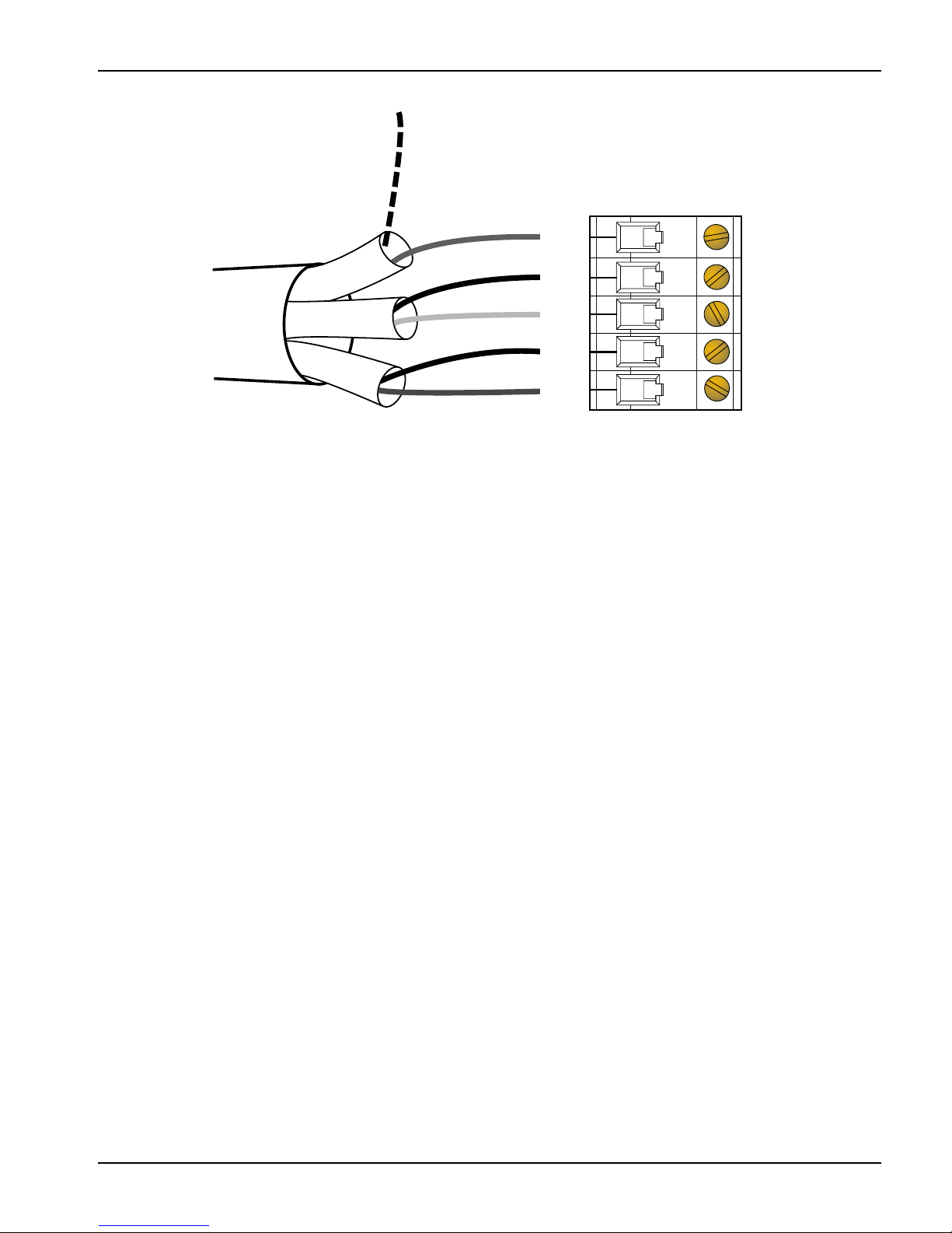
Shielding should be terminated to earth ground at the KING-
GAGE LevelPRO processor or other external device supplying
Vdc power to the current loop circuit. The other end of the
cable shielding should be connected to the terminal block in
the supplied junction enclosure (see detail for shield terminal
location).
Terminate shield to earth ground at one
point only!
• Note that chassis ground (or backplane) of many PLCs are
connected to earth ground.
• If necessary, you may use the back plate of LevelPRO for
making earth ground connections.
20 Vdc 24Vdc 28Vdc 32Vdc
500 ohms 700 ohms 900 ohms 1100 ohms
+ - SHIELD
4-20 mA
+24V
—
+
2
13
TMP
Signal Output
Terminals
(4-20 mAdc)
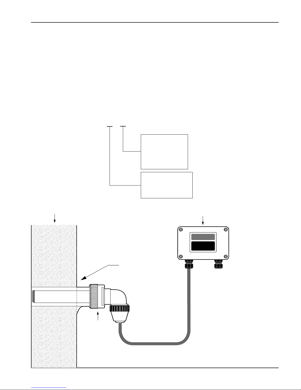
Water-Tight
Cord Grip Fitting
Sensor Input
Connector
Junction
Board
YEL.
GRN.
WHT.
BLK.
RED
4-20 mA OUTPUT
ZERO SPAN
CAUTION
-
+
-
+
METER