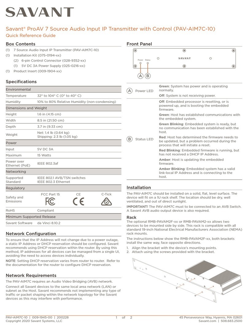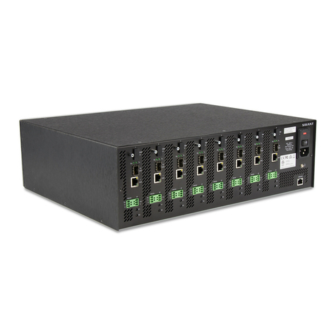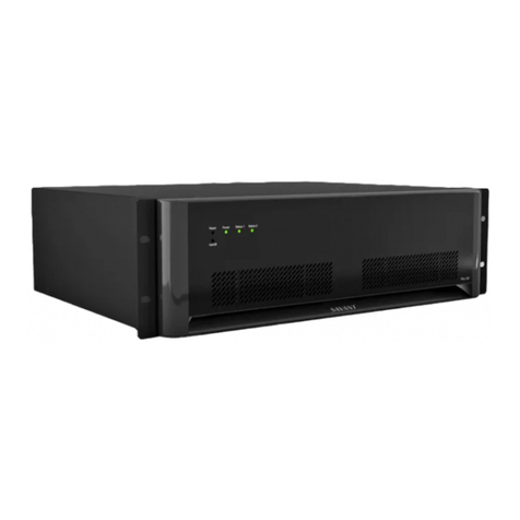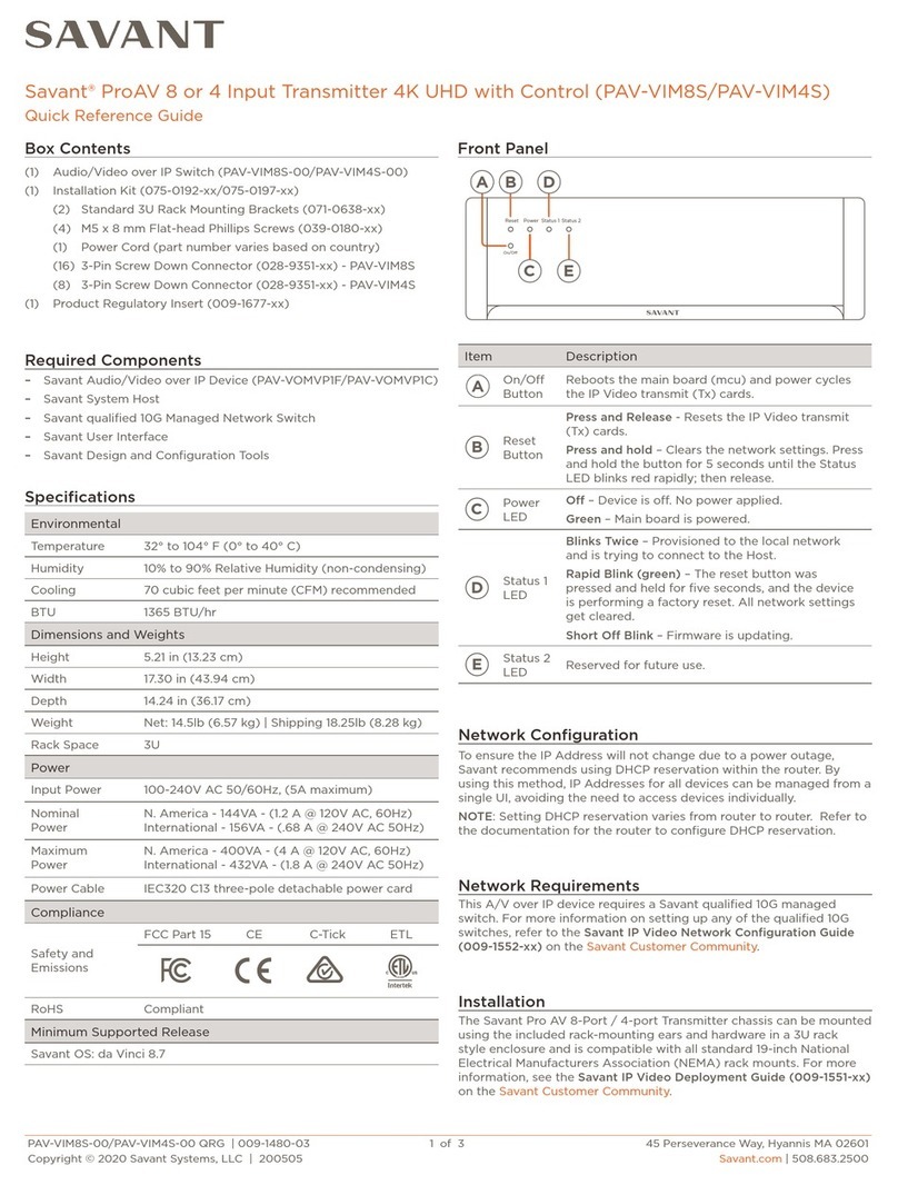
PAV-VIM8S-00/PAV-VIM4S-00 | 009-1480-02 | 180205
Copyright 2018 Savant Systems, LLC
45 Perseverance Way, Hyannis, MA 02601
Savant.com | 508.683.2500
2 of 2
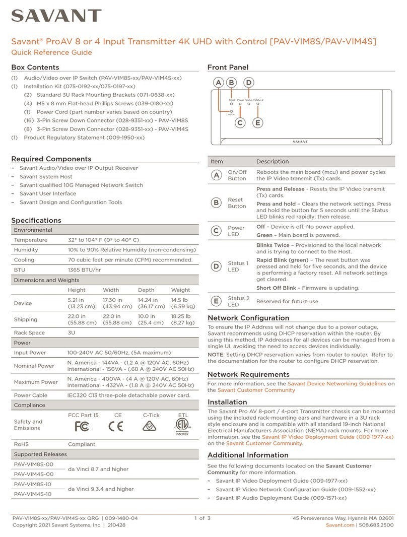
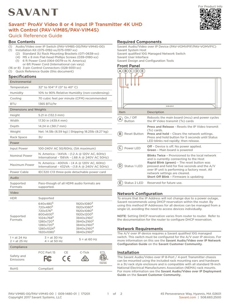
Item Description
1 Gigabit
Ethernet
1G of reserved network data bandwidth
commonly used to connect any network
compliant device to transmit its data onto the
Ethernet network by sharing the 10G network
link. 8-Pin RJ-45 female connection.
IMPORTANT!: Do not connect these ports to a
network switch.
10 Gigabit
Ethernet
SFP+ Housing; Used for connectivity to the 10G
Ethernet Network Switch
IMPORTANT!: For all 10G connections, use only
Savant certified SFP+ Direct-Attach Copper
(DAC) cables, or Savant certified fiber and fiber
connectors along with Savant certified SFP+
modules.
Rx/Tx LEDs
(10 GbE)
Rx – Link Activity LED indicator for all data
received on the 10G connection
Tx – Link Activity LED indicator for all data
transmitted from the 10G connection
HDMI In
19-Pin Type A HDMI female digital audio/video
input.
Supports HDMI 2.0a
HDMI 2.0 compliant cable is required for 4K
content.
Power Input
Module
100-240V AC 5A 50/60Hz power input module
with On/O switch.
I – Applies power to the device.
O – Removes power to the device.
NOTE: Includes a field replaceable 5A 250V Fast
acting fuse.
RS-232
Control Port
RS232 – 3-pin Screw down plug-in connection.
Transmits and receives serial data to and from
serial controllable devices. For pin-out informa-
tion, refer to the RS-232 Wiring section below.
IR Control
Port
IR - 3-pin Screw down plug-in connection.
Transmits IR signals via an IR Flasher
(5V tolerant) to devices with an IR input or IR
receiver. For pin-out information, refer to the IR
Wiring section below.
Analog
Audio Out
RCA Analog Audio Output.
Requires HDMI input stereo PCM audio format.
Direct Line Level 2.1-VRMS Output
Push Buttons Push buttons – Reserved for future use.
Ethernet 8-Pin RJ-45 female connection. Used to
communicate with the Savant System Host.
Reserved 8-Pin RJ-45 female connection;
Reserved for future use
Grounding Chassis Ground (optional)
A
B
C
D
E
F
G
H
I
J
K
L
LRLR R LRL L
R R L L
R R
LKJ
I
HGF
ED
C
B
A
Rear Panel Wiring and Connections
IR connections are made using a 3-pin
Control Connector supplied with the device.
The wire slips into the hole and locks with a
screw located at the top of the connector.
IMPORTANT: IR Wiring Precautions
Ensure that all IR emitters are within 15 feet
(4.6 meters) from the controller’s location.
Use of 3rd party blinking IR emitters with
Talk Back is not recommended. These types of emitters can draw
voltage away from the IR signal that can degrade IR performance.
3
2
1
PIN 1
IR -
PIN R +
PIN 3
Not Used
Out
G
IR Wiring
2 I
Serial control connections are made using
a 3-pin Control Connector supplied with
the device. The wire slips into the hole and
locks with a screw located at the top of the
connector.
RS-232 Wiring
3
2
1
PIN 1
Ground
PIN ransmit
PIN 3
Receive
Rx
Tx
G
2 T
Enhanced small form-factor pluggable connection. Use
a Savant certified Direct Access Copper (DAC) SFP+
cable to connect the chassis to the 10G switch, or Savant
certified fiber and fiber connectors along with Savant
certified SFP+ modules.
Transport Distance
DAC cable 6 ft (2 m)
OM3 multi-mode Fiber 1000ft (300 m)
SFP+ 10 GbE
Replace the Fuse
A
B
Connection Pins Towards Unit
Open Side of Cartridge Towards Power Switch
A
B
ELECTRIC SHOCK HAZARD: Disconnect the unit from AC power
by removing the power cord from the AC outlet and the unit before
replacing the fuse.
IMPORTANT: The orientation of the cartridge within the unit and lo-
cation of the fuse within the cartridge are crucial to proper operation.
Make note of the orientation of the cartridge and the fuse location
within the cartridge before removing.
1. Disconnect the unit from AC power by removing the power cord.
2. Open the fuse cover on the AC power input using a flat head
screwdriver or similar thin flat head tool. This will allow access to the
fuse cartridge.
3. Using a flat head screwdriver or similar thin flat head tool, gently
loosen the cartridge and pull the cartridge out of the unit slowly. As
the cartridge is removed, make note of the orientation, as it is import-
ant to proper operation.
TIP: Mark the chassis and fuse holder with a marker in order to align
when replacing.
4. Remove the old fuse from the cartridge and discard.
5. Gently place the new fuse in
the cartridge and place the
cartridge part way into the
receptacle aligning it as
defined in the diagram.
6. Gently press on the cartridge the rest of the way until it seats into
the terminals at the rear of the slot.
NOTE: If any resistance is encountered during seating the cartridge,
DO NOT apply more pressure. Stop pressing on the cartridge, remove
it, verify the orientation, and repeat step.
Additional Information
Refer to the following documents located on the Savant Customer
Community for additional information.
– Savant Video over IP Deployment Guide (009-1551-xx)
– Savant Video over IP Network Configuration Guide
(009-1552-xx)
