the FCC rules. These limits are designed to provide reasonable
protection against harmful interference when the equipment is operated
in a commercial environment. This equipment generates, uses and can
radiate radio frequency energy and, if not installed and used in
accordance with the instruction manual, may cause harmful interference
to radio communications. Operation of this equipment in a residential
area is likely to cause harmful interference, in which case the user will be
required to correct the interference at their expense. The following
techniques can be used to reduce interference problems:
1. Disconnect the equipment from its power source to verify that it is or
is not the source of the interference.
2. If the equipment is connected to the same outlet as the device
experiencing interference, connect the equipment to a different
outlet.
3. Move the equipment away from the device receiving the interference.
4. Reposition the receiving antenna for the device receiving the
interference.
5. Try combinations of the above.
2.2 Product overview
Respirometric Biological Oxygen Demand (BOD) is a test that measures
the quantity of oxygen consumed by bacteria that oxidize organic matter
in a water sample. The test is used to measure waste loadings at
wastewater treatment plants and to examine the efficiency of wastewater
treatment.
The instrument is sealed to prevent external atmospheric pressure
changes in the test bottle. The pressure in the sample bottles is
monitored. Bacteria in the sample use oxygen when they consume
organic matter. This oxygen consumption causes the pressure in the
bottle head space to drop. The pressure drop correlates directly to BOD.
During a test period, stir bars mix the sample and cause oxygen to move
from the air in the bottle to the sample. This helps simulate natural
conditions.
Carbon dioxide is a result of the oxidation process and can interfere with
a measurement. The instrument continuously removes carbon dioxide
from the system so that the monitored pressure difference stays
proportional to the quantity of oxygen used. Pressure changes in the
closed system are shown graphically in milligrams per liter (mg/L) on a
liquid crystal display. The instrument gives 360 uniform data points over
the selected time period.
The instrument adjusts for any negative errors produced when heat is
applied to a sample. The instrument does not start the test until the
temperature gets to equilibrium.
2.3 Product components
Make sure that all components have been received. If any of these items
are missing or damaged, contact the manufacturer or a sales
representative immediately.
• BODTrak™ II instrument
• A UL/CSA approved 115 VAC power cord with a NEMA 5-15P style
plug
• A 230 VAC harmonized power cord with a continental European plug
• Power supply, auto-switching between 115 V and 230 V
• Seal cups (6x)
• BODTrak II amber sample bottles (6x)
• BODTrak II magnetic stir bars (6x)
• Spatula scoop
• Nutrient buffer solution pillows (1 pkg)
• Potassium hydroxide pellets (1 container)
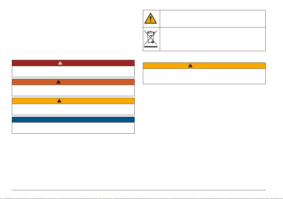
Section 3 Installation
3.1 External connections
Figure 1 shows the locations of the power switch and external
connections.
English 5