Hach Polymetron 9586 User manual

DOC023.52.93069
Polymetron 9586 Oxygen
Scavenger Analyzer
05/2018, Edition 6
User Manual


Table of Contents
Specifications.............................................................................................................. 3
General information.................................................................................................. 4
Safety information........................................................................................................ 4
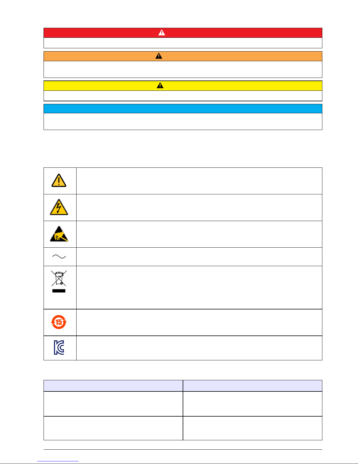
Use of hazard information.................................................................................... 5
Precautionary labels ............................................................................................ 5
EMC compliance statement (Korea)..................................................................... 5
Certification ........................................................................................................... 6
Product components.................................................................................................... 6
Product overview......................................................................................................... 7
Installation..................................................................................................................... 7
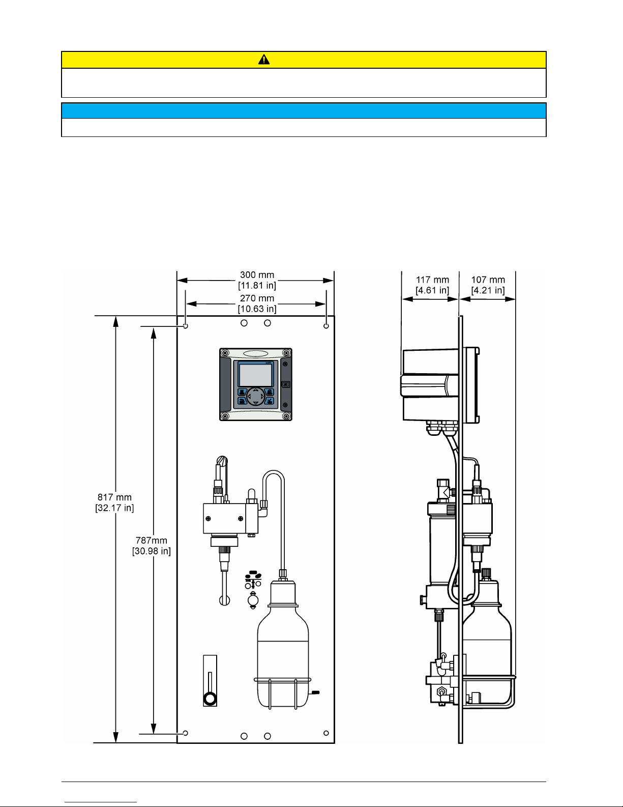
Analyzer mounting....................................................................................................... 8
Wiring overview........................................................................................................... 9
High-voltage barrier.............................................................................................. 9
Wiring for power................................................................................................... 9
Alarms and relays............................................................................................... 12
Wiring relays....................................................................................................... 12
Analog output connections................................................................................. 14
Discrete input wiring connections....................................................................... 15
Connect the optional digital communication output............................................ 17
Install a Secure Digital (SD) memory card ........................................................ 17
Plumb the sample and drain lines.............................................................................. 17
Install the reagents.................................................................................................... 18
Startup........................................................................................................................... 18
User interface and navigation............................................................................ 18
User interface............................................................................................................ 18
Display....................................................................................................................... 19
Additional display formats................................................................................... 20
Graphical display................................................................................................ 20
System startup.......................................................................................................... 21
Set the language, date and time for the first time ..................................................... 21
Controller configuration information........................................................................... 21
Using the secure digital memory (SD) card............................................................... 23
Updating software............................................................................................... 23
Save data and event logs with SD cards............................................................ 23
Access data and event log files on the SD card................................................. 24
Firmware updates with SD cards........................................................................ 25
Backup settings to an SD card........................................................................... 25
Restore settings to the controller........................................................................ 25
Transfer settings to another device.................................................................... 25
Operation..................................................................................................................... 26
Configure the sensor................................................................................................. 26
Calibration .................................................................................................................. 26
About sensor calibration..................................................................................... 26
Temperature calibration...................................................................................... 26
Zero calibration................................................................................................... 27
1

Calibration with the process sample................................................................... 27
Exit calibration procedure................................................................................... 28
Change calibration options................................................................................. 28
Reset calibration options.................................................................................... 29
Maintenance............................................................................................................... 29
Cleaning and decontamination.................................................................................. 29
Fuse replacement...................................................................................................... 29
Battery replacement................................................................................................... 29
Troubleshooting....................................................................................................... 29
General troubleshooting............................................................................................ 29
Test and maintenance menu..................................................................................... 31
Sensor diagnostic and test menu.............................................................................. 32
Warning and error conditions..................................................................................... 33
Warning list......................................................................................................... 33
Error list.............................................................................................................. 34
Replacement parts and accessories............................................................... 34
Material safety data sheets (MSDS)................................................................. 35
MSDS - Diisopropylamine.......................................................................................... 35
Table of Contents
2

Specifications
Specifications are subject to change without notice.
Panel
Specification Details
Dimensions 817 x 300 x 140 mm (32.2 x 11.8 x 5.5 in)
Weight 14.6 kg (32.15 lbs)
Sample flow rate 10—15 liters/hour
Working pressure 0.5—6 bar (7—87 psi)
Ambient temperature 0—60 °C (-32—140 °F)
Relative humidity 10—90%
Working electrode Platinum
Counter electrode Stainless steel
Reference Ag / AgCl / KCl 0.1 M
Measuring cell Acrylic
Sample conditioner DIPA (diisopropylamine)
European standards EN 61326 Class A for EMC; EN 601010-1 for low voltage safety
International standards cETLus
Sensor
Specification Details
Measuring range 0—500 ppb hydrazine; 0—100 ppb carbohydrazide
Sensitivity < 0.2 ppb
Repeatability 1 ppb or ± 2% of measurement whichever is the greater
Detection limit ≤ 1 ppb
Response time < 60 seconds
Sample temperature measurement range 5—45 °C (41—113 °F)
Controller
Specification Details
Component description Microprocessor-controlled and menu-driven controller that operates the sensor and
displays measured values.
Operating temperature -20 to 60 ºC (-4 to 140 ºF); 95% relative humidity, non-condensing with sensor load
<7 W; -20 to 50 ºC (-4 to 104 ºF) with sensor load <28 W
Storage temperature -20 to 70 ºC (-4 to 158 ºF); 95% relative humidity, non-condensing
Enclosure1NEMA 4X/IP66 metal enclosure with a corrosion-resistant finish
1Units that have the Underwriters Laboratories (UL) certification are intended for indoor use only
and do not have a NEMA 4X/IP66 rating.
English 3

Specification Details
Power requirements AC powered controller: 100-240 VAC ±10%, 50/60 Hz; Power 50 VA with 7 W
sensor/network module load, 100 VA with 28 W sensor/network module load
(optional Modbus, RS232/RS485, Profibus DPV1 or HART network connection).
24 VDC powered controller: 24 VDC—15%, + 20%; Power 15 W with 7 W
sensor/network module load, 40 W with 28 W sensor/network module load (optional
Modbus, RS232/RS485, Profibus DPV1 or HART network connection).
Altitude requirements Standard 2000 m (6562 ft) ASL (Above Sea Level)
Pollution
degree/Installation
category
Polution Degree 2; Installation Category II
Outputs Two analog (0-20 mA or 4-20 mA) outputs. Each analog output can be assigned to
represent a measured parameter such as pH, temperature, flow or calculated
values. Optional module supplies three additional analog outputs (5 total).
Relays Four SPDT, user-configured contacts, rated 250 VAC, 5 Amp resistive maximum for
the AC powered controller and 24 VDC, 5A resistive maximum for the DC powered
controller. Relays are designed for connection to AC Mains circuits (i.e., whenever
the controller is operated with 115 - 240 VAC power) or DC circuits (i.e., whenever
the controller is operated with 24 VDC power).
Dimensions ½ DIN—144 x 144 x 180.9 mm (5.7 x 5.7 x 7.12 in.)
Weight 1.7 kg (3.75 lb)
Compliance information2CE approved (with all sensor types). Listed for use in general locations to UL and
CSA safety standards by ETL (with all sensor types).
Certain AC mains powered models are listed for use in general safety locations to
UL and CSA safety standards by Underwriters Laboratories (with all sensor types).
Digital communication Optional Modbus, RS232/RS485, Profibus DPV1 or HART network connection for
data transmission
Data logging Secure Digital Card (32 GB maximum) or special RS232 cable connector for data
logging and performing software updates. The controller will keep approximately
20,000 data points per sensor.
Warranty 2 years
General information
In no event will the manufacturer be liable for direct, indirect, special, incidental or consequential
damages resulting from any defect or omission in this manual. The manufacturer reserves the right to
make changes in this manual and the products it describes at any time, without notice or obligation.
Revised editions are found on the manufacturer’s website.
Safety information
N O T I C E
The manufacturer is not responsible for any damages due to misapplication or misuse of this product including,
without limitation, direct, incidental and consequential damages, and disclaims such damages to the full extent
permitted under applicable law. The user is solely responsible to identify critical application risks and install
appropriate mechanisms to protect processes during a possible equipment malfunction.
Please read this entire manual before unpacking, setting up or operating this equipment. Pay
attention to all danger and caution statements. Failure to do so could result in serious injury to the
operator or damage to the equipment.
Make sure that the protection provided by this equipment is not impaired. Do not use or install this
equipment in any manner other than that specified in this manual.
2DC powered units are not listed by UL.
4 English

Use of hazard information
D A N G E R
Indicates a potentially or imminently hazardous situation which, if not avoided, will result in death or serious injury.
WARNING
Indicates a potentially or imminently hazardous situation which, if not avoided, could result in death or serious
injury.
CAUTION
Indicates a potentially hazardous situation that may result in minor or moderate injury.
N O T I C E
Indicates a situation which, if not avoided, may cause damage to the instrument. Information that requires special
emphasis.
Precautionary labels
Read all labels and tags attached to the product. Personal injury or damage to the product could
occur if not observed. A symbol on the instrument is referenced in the manual with a precautionary
statement.
This symbol, when noted on a product, indicates a potential hazard which could cause serious
personal injury and/or death. The user should reference this instruction manual for operation and/or
safety information.
This symbol, when noted on a product enclosure or barrier, indicates that a risk of electrical shock
and/or electrocution exists and indicates that only individuals qualified to work with hazardous
voltages should open the enclosure or remove the barrier.
This symbol, when noted on the product, indicates the presence of devices sensitive to electrostatic
discharge and indicates that care must be taken to prevent damage to them.
This symbol, when noted on a product, indicates the instrument is connected to alternate current.
Electrical equipment marked with this symbol may not be disposed of in European public disposal
systems. In conformity with European local and national regulations, European electrical equipment
users must now return old or end-of-life equipment to the manufacturer for disposal at no charge to
the user.
Note: For return for recycling, please contact the equipment producer or supplier for instructions on how to return
end-of-life equipment, producer-supplied electrical accessories, and all auxiliary items for proper disposal.
Products marked with this symbol indicates that the product contains toxic or hazardous substances
or elements. The number inside the symbol indicates the environmental protection use period in
years.
Products marked with this symbol indicates that the product conforms to relevant South Korean
EMC standards.
EMC compliance statement (Korea)
Type of equipment Additional information
A 급 기기
( 업무용 방송통신기자재 )
이 기기는 업무용 (A 급 ) 전자파적합기기로서 판매자 또
는 사용자는 이 점을 주의하시기 바라며, 가정외의 지역
에서 사용하는 것을 목적으로 합니다.
Class A equipment
(Industrial Broadcasting and Communication
Equipment)
This equipment meets Industrial (Class A) EMC
requirements. This equipment is for use in industrial
environments only.
English 5

Certification
Canadian Radio Interference-Causing Equipment Regulation, IECS-003, Class A:
Supporting test records reside with the manufacturer.
This Class A digital apparatus meets all requirements of the Canadian Interference-Causing
Equipment Regulations.
FCC Part 15, Class "A" Limits
Supporting test records reside with the manufacturer. The device complies with Part 15 of the FCC
Rules. Operation is subject to the following conditions:
1. The equipment may not cause harmful interference.
2. The equipment must accept any interference received, including interference that may cause
undesired operation.
Changes or modifications to this equipment not expressly approved by the party responsible for
compliance could void the user's authority to operate the equipment. This equipment has been tested
and found to comply with the limits for a Class A digital device, pursuant to Part 15 of the FCC rules.
These limits are designed to provide reasonable protection against harmful interference when the
equipment is operated in a commercial environment. This equipment generates, uses and can
radiate radio frequency energy and, if not installed and used in accordance with the instruction
manual, may cause harmful interference to radio communications. Operation of this equipment in a
residential area is likely to cause harmful interference, in which case the user will be required to
correct the interference at their expense. The following techniques can be used to reduce
interference problems:
1. Disconnect the equipment from its power source to verify that it is or is not the source of the
interference.
2. If the equipment is connected to the same outlet as the device experiencing interference, connect
the equipment to a different outlet.
3. Move the equipment away from the device receiving the interference.
4. Reposition the receiving antenna for the device receiving the interference.
5. Try combinations of the above.
Product components
Make sure that all components have been received. If any items are missing or damaged, contact the
manufacturer or a sales representative immediately.
6 English

Product overview
The analyzer is designed to continuously measure the amount of oxygen scavengers (hydrazine or
carbohydrazide) in water.
Figure 1 Front and rear view
1 Controller 6 Chemical zero cartridge (option)
2 Measuring cell 7 Pressure regulator
3 Chemical zero on/off (option) 8 Sample in, 4/6 mm tube
4 Flow meter 9 Sample drain, 6/8 mm tube, atmospheric pressure
5 Sample conditioning bottle (DIPA)
Installation
CAUTION
Multiple hazards. Only qualified personnel must conduct the tasks described in this section of the
document.
English 7

Analyzer mounting
CAUTION
Personal injury hazard. Instruments or components are heavy. Use assistance to install or move. Make sure that
the wall mounting is able to hold 4 times the weight of the equipment.
N O T I C E
The analyzer must be aligned vertically to guarantee accuracy.
Attach the analyzer to a stable, vertical surface. Use a level to make sure that the analyzer is
completely vertical. Refer to the guidelines that follow.
• Put the instrument in a location that has access for operation, service and calibration.
• Make sure that there is good view of the display and controls.
• Keep the instrument away from a heat source.
• Keep the instrument away from vibrations.
• Keep the sample tubing as short as possible to minimize the response time.
• Make sure that there is no air in the sample supply line.
8 English

Wiring overview
Figure 2 shows an overview of the wiring connections inside the controller with the high voltage
barrier removed. The left side of the figure shows the back side of the controller cover.
Note: Remove connector caps from the connectors before module installation.
Figure 2 Wiring connections overview
1 Service cable connection 5 AC and DC power connector39 Discrete input wiring connector3
2 4-20 mA output36 Ground terminals 10 Digital sensor connector3
3 Sensor module connector 7 Relay connections3
4 Communication module
connector (e.g., Modbus,
Profibus, HART, optional
4-20 mA module, etc.)
8 Digital sensor connector3
High-voltage barrier
High-voltage wiring for the controller is located behind the high-voltage barrier in the controller
enclosure. The barrier must remain in place except when installing modules or when a qualified
installation technician is wiring for power, alarms, outputs or relays. Do not remove the barrier while
power is applied to the controller.
Wiring for power
WARNING
Potential Electrocution Hazard. Always disconnect power to the instrument when making electrical
connections.
3Terminals can be removed for improved access.
English 9

WARNING
Potential Electrocution Hazard. If this equipment is used outdoors or in potentially wet locations, a
Ground Fault Interrupt device must be used for connecting the equipment to its mains power source.
D A N G E R
Electrocution Hazard. Do not connect AC power to a 24 VDC powered model.
WARNING
Potential Electrocution Hazard. A protective earth (PE) ground connection is required for both
100-240 VAC and 24 VDC wiring applications. Failure to connect a good PE ground connection can
result in shock hazards and poor performance due to electromagnetic interferences. ALWAYS connect
a good PE ground to the controller terminal.
N O T I C E
Install the device in a location and position that gives easy access to the disconnect device and its operation.
The controller can be purchased as either a 100-240 VAC powered model or a 24 VDC powered
model. Follow the appropriate wiring instructions for the purchased model.
The controller can be wired for line power by hard-wiring in conduit or wiring to a power cord.
Regardless of the wire used, the connections are made at the same terminals. A local disconnect
designed to meet local electrical code is required and must be identified for all types of installation. In
hard-wired applications, the power and safety ground service drops for the instrument must be 18 to
12 AWG.
Notes:
• The voltage barrier must be removed before making any electrical connections. After making all
connections, replace the voltage barrier before closing the controller cover.
• A sealing type strain relief and a power cord less than 3 meters (10 feet) in length with three 18-
gauge conductors (including a safety ground wire) can be used to maintain the NEMA
4X/IP66 environmental rating.
• Controllers can be ordered with AC power cords pre-installed. Additional power cords may also be
ordered.
• The DC power source that supplies power to the 24 VDC powered controller must maintain
voltage regulation within the specified 24 VDC-15% +20% voltage limits. The DC power source
must also provide adequate protection against surges and line transients.
Wiring procedure
Refer to the illustrated steps that follow and Table 1 or Table 2 to wire the controller for power. Insert
each wire into the appropriate terminal until the insulation is seated against the connector with no
bare wire exposed. Tug gently after insertion to make sure that there is a secure connection. Seal
any unused openings in the controller box with conduit opening sealing plugs.
Table 1 AC power wiring information (AC powered models only)
Terminal Description Color—North America Color—EU
1 Hot (L1) Black Brown
2 Neutral (N) White Blue
— Protective Earth (PE) Ground lug Green Green with yellow stripe
10 English

Table 2 DC power wiring information (DC powered models only)
Terminal Description Color—North America Color—EU
1 +24 VDC Red Red
2 24 VDC return Black Black
— Protective Earth (PE) Ground lug Green Green with yellow stripe
English 11

Alarms and relays
The controller is equipped with four unpowered, single pole relays rated 100-250 VAC, 50/60 Hz,
5 amp resistive maximum. Contacts are rated 250 VAC, 5 amp resistive maximum for the AC
powered controller and 24 VDC, 5A resistive maximum for the DC powered controller. The relays are
not rated for inductive loads.
Wiring relays
WARNING
Potential Electrocution Hazard. Always disconnect power to the instrument when making electrical
connections.
WARNING
Potential fire hazard. The relay contacts are rated 5A and are not fused. External loads connected to
the relays must have current limiting devices provided to limit current to < 5 A.
WARNING
Potential fire hazard. Do not daisy-chain the common relay connections or jumper wire from the mains
power connection inside the instrument.
WARNING
Potential electrocution hazard. In order to maintain the NEMA/IP environmental ratings of the
enclosure, use only conduit fittings and cable glands rated for at least NEMA 4X/IP66 to route cables in
to the instrument.
AC line (100—250 V) powered controllers
12 English

WARNING
Potential electrocution hazard. AC mains powered controllers (115 V–230 V) are designed for relay
connections to AC mains circuits (i.e., voltages greater than 16 V-RMS, 22.6 V-PEAK or 35 VDC).
The wiring compartment is not designed for voltage connections in excess of 250 VAC.
24 VDC powered controllers
WARNING
Potential electrocution hazard. 24 V powered controllers are designed for relay connections to low
voltage circuits (i.e., voltages less than 16 V-RMS, 22.6 V-PEAK or 35 VDC).
The 24 VDC controller relays are designed for the connection to low voltage circuits (i.e., voltages
less than 30 V-RMS, 42.2 V-PEAK or 60 VDC). The wiring compartment is not designed for voltage
connections above these levels.
The relay connector accepts 18–12 AWG wire (as determined by load application). Wire gauge less
than 18 AWG is not recommended.
The Normally Open (NO) and Common (COM) relay contacts will be connected when an alarm or
other condition is active. The Normally Closed (NC) and Common relay contacts will be connected
when an alarm or other condition is inactive (unless the Fail Safe is set to Yes) or when power is
removed from the controller.
Most relay connections use either the NO and COM terminals or the NC and COM terminals. The
numbered installation steps show connection to the NO and COM terminals.
English 13

Analog output connections
WARNING
Potential Electrocution Hazard. Always disconnect power to the instrument when making electrical
connections.
WARNING
Potential electrocution hazard. In order to maintain the NEMA/IP environmental ratings of the
enclosure, use only conduit fittings and cable glands rated for at least NEMA 4X/IP66 to route cables in
to the instrument.
Two isolated analog outputs (1 and 2) are provided (Figure 3). Such outputs are commonly used for
analog signaling or to control other external devices.
Make wiring connections to the controller as shown in Figure 3 and Table 3.
Note: Figure 3 shows the back of the controller cover and not the inside of the main controller compartment.
Table 3 Output connections
Recorder wires Circuit board position
Output 2– 4
Output 2+ 3
Output 1– 2
Output 1+ 1
1. Open the controller cover.
2. Feed the wires through the strain relief.
3. Adjust the wire as necessary and tighten the strain relief.
14 English

4. Make connections with twisted-pair shielded wire and connect the shield at the controlled
component end or at the control loop end.
• Do not connect the shield at both ends of the cable.
• Use of non-shielded cable may result in radio frequency emission or susceptibility levels higher
than allowed.
• Maximum loop resistance is 500 ohm.
5. Close the controller cover and tighten the cover screws.
6. Configure outputs in the controller.
Figure 3 Analog output connections
Discrete input wiring connections
WARNING
Potential Electrocution Hazard. Always disconnect power to the instrument when making electrical connections.
WARNING
Potential electrocution hazard. In order to maintain the NEMA/IP environmental ratings of the enclosure, use only
conduit fittings and cable glands rated for at least NEMA 4X/IP66 to route cables in to the instrument.
Three discrete inputs are provided for switch closure inputs or logic level voltage inputs. Make wiring
connections and configure jumper settings to the controller as shown in Figure 4, Table 4 and
Figure 5.
Note: Figure 4 shows the back of the controller cover and not the inside of the main controller compartment.
English 15

Figure 4 Discrete input wiring connections
Table 4 Input connections
Discrete inputs Connector position - Switch input Connector position - Voltage
input
Input 1+ 3 2
Input 1- 2 3
Input 2+ 6 5
Input 2- 5 6
Input 3+ 8 7
Input 3- 7 8
Figure 5 Jumper settings
1 Input 1 configuration jumpers 3 Input 3 configuration jumpers 5 Jumpers positioned to the right
for voltage inputs
2 Input 2 configuration jumpers 4 Jumpers positioned to the left for
switch inputs
1. Open the controller cover.
2. Feed the wires through the cable gland.
3. Adjust the wire as necessary and tighten the cable gland.
4. The jumpers are positioned immediately behind the connector. Remove the connector for
improved access to the jumpers and configure the jumper settings according to the type of input
as shown in Figure 5.
16 English

5. Close the controller cover and tighten the cover screws.
6. Configure inputs in the controller.
Note: In switch input mode the controller supplies 12 volts to the switch and is not isolated from the controller. In
voltage input mode the inputs are isolated from the controller (user input voltage from 0 to 30 volts).
Connect the optional digital communication output
The manufacturer supports Modbus RS485, Modbus RS232, Profibus DPV1 and HART
communication protocols. The optional digital output module is installed in the location indicated by
item 4 in Figure 2 on page 9. Refer to the instructions supplied with the network module for more
details.
For information about Modbus registers, go to http://www.hach-lange.com or http://www.hach.com
and search Modbus registers or go to any sc200 product page.
Install a Secure Digital (SD) memory card
For instructions on how to install an SD card in the controller, refer to Figure 6. Information on how to
use the SD memory card can be found in Using the secure digital memory (SD) card on page 23.
To remove an SD card, push down on the edge of the card and release, then pull the card up and out
of the slot. After the card is removed, close the slot cover and tighten the cover screws.
Figure 6 SD card installation
Plumb the sample and drain lines
Connect the sample and drain lines to the fittings on the back of the panel.
1. Connect the sample line to the inlet 4/6-mm OD tube fitting.
2. Connect a drain line to the drain 6/8-mm OD tube fitting. Keep the drain line as short as possible
at atmospheric pressure.
English 17

Install the reagents
WARNING
Chemical exposure hazard. Obey laboratory safety procedures and wear all of the personal protective
equipment appropriate to the chemicals that are handled. Refer to the current safety data sheets
(MSDS/SDS) for safety protocols.
1. Fill the empty sample conditioning bottle with DIPA (diisopropylamine) and enter the hazardous
reagent information on the blank label attached to the bottle.
2. Install the sample conditioning bottle on the front of the analyzer.
3. Connect the supplied tube to the measuring cell. Install the tube completely into the bottle of
conditioning solution. Make sure that the tube fittings are tight to prevent leakage of fumes from
the conditioning bottle into the atmosphere.
4. If the chemical zero cartridge is used, install the cartridge on the rear of the analyzer.
Startup
Make sure that the flow rate and pressure do not exceed the values in Specifications on page 3.
1. Open the valve on the sample line to let sample flow through the analyzer.
2. Turn the knob on the flow meter to set the flow rate.
3. Examine the plumbing for leaks and stop any leaks if found.
4. Apply power to the controller.
5. Make the applicable menu selections when the controller starts.
User interface and navigation
User interface
The keypad has four menu keys and four directional keys as shown in Figure 7.
18 English
Table of contents
Other Hach Measuring Instrument manuals

Hach
Hach Orbisphere 51 Series Quick manual

Hach
Hach DR/2010 User manual

Hach
Hach DR1300 FL User manual

Hach
Hach PAT700 DS Quick manual

Hach
Hach HIAC 9705 User manual

Hach
Hach DR/820 User manual

Hach
Hach 2100Q User manual

Hach
Hach Polymetron 9610sc SiO2 User manual

Hach
Hach sensION+ pH3 User manual

Hach
Hach sensION+ EC5 DL User manual

Hach
Hach Hach SL1000 User manual

Hach
Hach H128 User manual

Hach
Hach DOC026.52.00769 User manual

Hach
Hach 5500sc SiO2 User manual

Hach
Hach SP-510 Quick manual

Hach
Hach FT660 sc Quick manual

Hach
Hach polymetron 9240 User manual

Hach
Hach Surface Scatter 7 sc User manual

Hach
Hach POLYMETRON 8810 ISE Quick manual

Hach
Hach POCKET COLORIMETER II User manual