Zenitel H952T User manual

TD 92022GB
2002-11-13/ Rev. A
Installation Guide
H/U952T Terminal Transmitter

TD 92022GB
2002-11-13/ Rev. A
Installation Guide
H/U952T Terminal Transmitter
Contents
1 General ......................................................................................................................................... 1
2 Board Description ....................................................................................................................... 2
3 Installation ................................................................................................................................... 3
3.1 Mounting ............................................................................................................................... 3
3.2 Mounting together with Other Units ...................................................................................... 4
3.3 Addressing the Transmitter ..................................................................................................... 4
3.4 Wiring Runs ........................................................................................................................... 5
3.5 Connection of Buses and Control Equipment ......................................................................... 6
3.6 Connection of Supply Voltage ................................................................................................ 7
3.7 Coax Connection to Antenna .................................................................................................7
3.8 Connection to Slave Transmitter ............................................................................................. 7
4 Parameter Settings ...................................................................................................................... 8
5 Installation Test Procedure ......................................................................................................... 8
5.1 Field Adjustment .................................................................................................................... 9
6 Circuit Board Replacement ......................................................................................................... 9
Appendix A: Installation of T952SM/FL Speech and Frequency Lock module ........................ 11
Appendix B: Coaxial Connectors ................................................................................................13

TD 92022GB
2002-11-13/ Rev. A
Installation Guide
H/U952T Terminal Transmitter
1
1 General
Figure 1. Terminal Transmitter H/U952T.
H/U952T Terminal Transmitter is used in the On-site Paging- and Personal Security
Systems. The transmitter operates in both UHF and HF frequency bands.
Versions
The transmitters are available in the following frequency bands:
Delivery includes
• H/U952T unit
• Coax connector TNC
• Modular bus cabling
Tools etc., required
•Screwdriver
• Screws for mounting
•Multi-meter
Related Documentation
As a complement to this installation guide, see also the applicable system installation
document:
• System Installation, On-site Paging System, TD 90227GB
• System Installation, Personal Security System, TD 90678GB
H952T U952T
Supply voltage: 12.5 V DC ± 10% 12.5 V DC ± 10%
Max. current consumption: 2.0 A 2.5 A
Max. current consumption
during transmission: 1.6 A 1.6 A
Max. current consumption
in stand by: 0.2 A 0.4 A
U952T: 425-475 MHz
H952T: 25-29 MHz, 29-32 MHz, 32-37 MHz, 37-42 MHz, 42-47 MHz, 47-50 MHz

TD 92022GB
2002-11-13/ Rev. A
Installation Guide
H/U952T Terminal Transmitter
2
2 Board Description
Figure 2. H/U952T Circuit board.
Connectors
J100, J101 For connecting D-, and SP-bus via modular bus cabling.
J102 Supply voltage.
J103 For connecting D-bus (if modular bus cabling is not used) and Control
Equipment.
J200 For connecting the Speech and Frequency (T952SM/FL) Lock module.
Switches
SW100 Address selector switch.
SW200 Test switch, set to OFF during normal operation.
J101
J100
SW100
J103
IC101
SW200
J200
J102
L301
LED100
P400
LED302
LED301
LED300
LED201
LED302
LED301
LED300
LED201
C444 (U952T)
L401 (H952T)
15

TD 92022GB
2002-11-13/ Rev. A
Installation Guide
H/U952T Terminal Transmitter
3
3 Installation
The unit should be placed in a dry environment. A temperature between 0 and +40°C is
preferred. The transmitter will operate in the temp range -15 up to +55°C. The transmitter
can be installed alone or together with other system units using the modular bus cabling
or twisted-pair wiring.
To prevent dust or moisture from damaging the electronics it is important to have the
cover mounted after installation and during use.
3.1 Mounting
The illustration below shows the dimensions for mounting the H/U952T.
Figure 3. Mounting dimensions in mm.
Note: To facilitate service after the unit is installed, we recommend a free space of about
150 mm above and 50 mm below the unit.
LEDs
LED100 Function indicator for green, red, or orange indication.
LED201 LED, TX ON, indicates carrier.
LED300 LED, TX DATA ON, indicates paging.
LED301 Indicates DSP running (blinks).
LED302 Indicates speech on.
Flash PROM
IC101 Program memory
Adjustable
Components
P400 Potentiometer, for calibration of output power.
L301 Inductance coil, for fine adjustment of reference frequency.
C444 Capacitor, for adjustment of VCO frequency. Note: Only U952T
L401 Inductance coil, for adjustment of VCO frequency. Note: Only H952T.
9 9
275
56.5
188.5
65 130
112
Dimensions (H x W x D)
275 x 130 x 60 mm

TD 92022GB
2002-11-13/ Rev. A
Installation Guide
H/U952T Terminal Transmitter
4
Use a screwdriver or similar to release the cover by applying a light pressure to the two
snap catches (1) and remove the cover (2).
Figure 4. Releasing the cover.
Note: The internal metal shield should not be opened.
3.2 Mounting together with Other Units
Figure 5. Mounting with other units.
1 Remove upper and lower covers. Fasten together the lower rectangular covers of
adjacent units (1).
2 Fasten each unit to the wall with three screws, see figure figure 3 on page 3.
3.3 Addressing the Transmitter
• Select the address by setting the address selector switch SW100, see the System
Installation document under Addressing.
Note:
1) The address for H/U952T must not be 00, nor the same as any other 900-unit D-bus
address.
2) In case the system includes speech, the transmitter must be in the address range for
speech transmitters (hex address 80-FF).
1
1
2
1
1

TD 92022GB
2002-11-13/ Rev. A
Installation Guide
H/U952T Terminal Transmitter
5
3.4 Wiring Runs
The plastic partition (shaded in the illustration) is scored to facilitate breaking at
convenient intervals.
Figure 6. Scored plastic partition for breaking.
1 Use pliers to break off a suitable section.
2 Run the wiring out through the cable duct at the bottom.
3 Use the slots at the opening to secure the wiring with cable straps.
Wiring can be run four ways for connection with other units:
Figure 7. Four ways of wiring runs.
• Remove the rectangular covers and run the cabling out through the side (1).
• Break off sections at short side of case and run the cabling downwards (2).
• Run the cabling through the round holes at the bottom of the case (3).
• Remove the circular covers at the top of the side case (4).
1 2 3 4 5
slots
2
1
2
3
1
3
4
4

TD 92022GB
2002-11-13/ Rev. A
Installation Guide
H/U952T Terminal Transmitter
6
3.5 Connection of Buses and Control Equipment
Buses are connected either via modular bus cabling or twisted-pairs.
Note: Data buses are polarized! Use only twisted-pairs for separate wiring!
Bus Connections via Modular Bus Cabling
Figure 8. Modular bus cable pins.
Note that only D- and SP-bus are used by the transmitter. When the modular bus cable is
used, no further connection of the SP-bus to T952SM/FL Speech and Frequency Lock
module is required.
• Connect the modular bus cabling to connectors J100 and J101, see figure 2 on page 2.
Bus Connections via twisted-pairs
Figure 9. Connection via twisted-pairs.
• Connect the D bus to connector J103, screw 1 and 2.
• If speech is used, see Connection of SP/FL bus via twisted-pairs on page 11 in
“Appendix A“.
Connection of Control Equipment
• Connect control of H/U954 Power Amplifier* to J103 screw 3 and 5, and H/U950SC
Output Power Surveillance Module* to J103 screw 4 and 5, see figure 9 above.
*See also the installation guides for the respective units.
Note: H/U989M Monitor Receiver (phased out product) is connected in the same ways as
H/U950SC.
Pin 1
234567
Pin 8
Pin
1
2
3
4
5
6
7
8
Signal
A1 data bus
A2 data bus
B1 data bus
B1 data bus
D1 data bus
D2 data bus
SP1 speech bus
SP2 speech bus
J100 + J101
J103
1 D1
2 D2
3 Booster control
4 Monitor input
5 GND
H/U952T
D-bus, connection
to a Central Unit
Control of H/U954
H/U950SC

TD 92022GB
2002-11-13/ Rev. A
Installation Guide
H/U952T Terminal Transmitter
7
3.6 Connection of Supply Voltage
• Connect supply voltage to connector J102 screw 1 and 2. See also the System
Installation document, under Power Supply.
Figure 10. Power supply connector.
3.7 Coax Connection to Antenna
• Connect the antenna coax to the antenna output connector located at the upper right
of the transmitter, see figure 1 on page 1.
• To prevent water from running along the antenna cable and entering the transmitter,
let the cable form a loop downwards. See figure 11 below.
Figure 11. Preventing water to run along the cable and entering the transmitter.
For assembly of the coax connector to the cable, see Appendix B.
3.8 Connection to Slave Transmitter
If the transmitter is to drive a slave transmitter, slave driver U952DR (UHF systems) or
power divider MPT-50 (HF systems) is to be installed between the transmitter and the
slave. The slave driver or power divider is connected to the antenna output, in series with
the coax from the antenna.
J102
3 +12V
4 GND
1 +12V
2 GND
Supply voltage-in
Supply voltage-out
H/U952T
Transmitter

TD 92022GB
2002-11-13/ Rev. A
Installation Guide
H/U952T Terminal Transmitter
8
For installation of U952DR Slave Driver, see Installation Guide for U952DR, TD 92038GB.
The installation of MPT-50 is described in the Installation Guide for H950S,TD 90318GB.
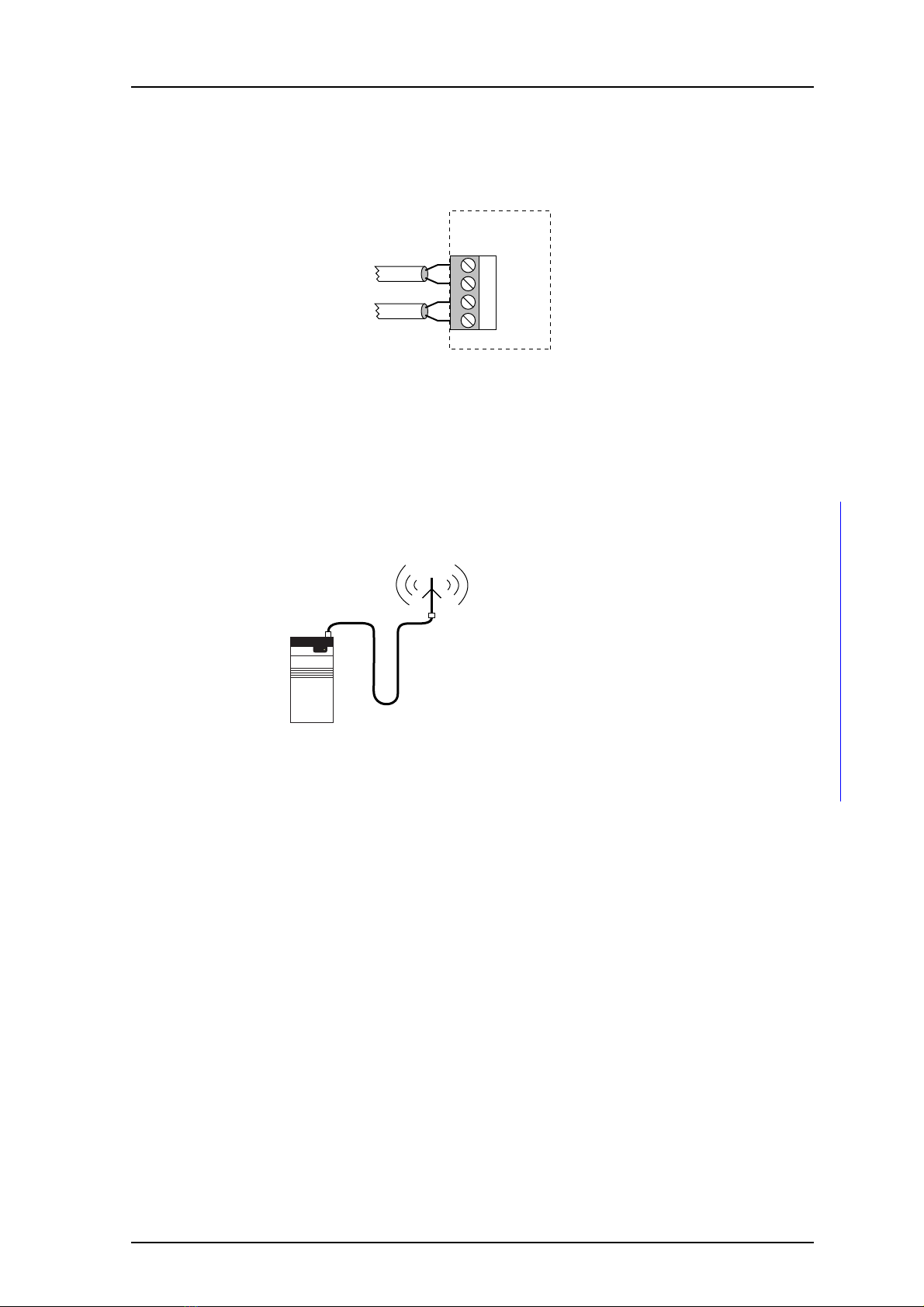
Figure 12. Connection to Slave Transmitter in an UHF-system.
4 Parameter Settings
All parameters must be set in the U/H952 Flash PROM IC 101, before the tuning
procedure. The instruction for programming fixed equipment is described in
General Description PCPAR, TD 90799GB. Note that licence is required when FOM/SFO or
FL is used.
1 Open PCPAR and select software S952T.
2 Set the transmitter frequency in Hz.
3 Set the channel spacing.
4 If there is speech in the system check:
• Subtone frequency (default 127.3 Hz).
When FL (frequency locking) is used check:
• That frequency locking is enabled with the right reference frequency.
5 When FOM or SFO is used this has to be enabled with the right offset.
6 If the transmitter is to be used with old central software that do not support
U/H952T (specified in the parameter list), set the transmitter to act as an
U/H950T.
7 If FOM/SFO or FL is used, enter the required licence code.
8 When you have edited the parameter list, download the changes to flash prom
IC 101 and exit PCPAR.
5 Installation Test Procedure
1 Check that all sections of switch SW200 on the transmitter are set to OFF.
2 Check that address switch SW100 has the right address, see the System Installation
document, under Addressing.
Transmitter
Slave Driver Slave Transmitter

TD 92022GB
2002-11-13/ Rev. A
Installation Guide
H/U952T Terminal Transmitter
9
3 Energize all units in the 900-system. Function indicator LED100 on the transmitter
should light red for about 1 second and then change to a flashing green.
If it continues to indicate steady red, check that supply voltage is 12.5 Vdc ± 10%.
Flashing red indicates a program fault, parameter fault, or a faulty 125 MHz
oscillator.
4 If H/U952T is connected to another unit, the indicator should show a steady green
indication within 90 seconds.
If the indicator continues to blink green, check:
• Polarity of data bus(es)
• Connections on H/U952T
• That H/U952T is properly addressed
• That all sections of SW200 is set to OFF
If everything seems to be OK but the function indicator still blinks, the fault is
probably located outside H/U952T:
Check the other 900-units according to the System Installation document, or
contact your dealer.
5 If T952SM/FL module is used:
• Check that T938RM is connected as a reference module if the transmitter is
included in a frequency locked system.
• When frequency locking is used it should be locked to a reference frequency
within 20 seconds, the indicator on the T952SM/FL module is lit red.
• Perform a speech test.
6 Initiate a paging from a unit. The LEDs TX ON and DATA ON lights momentarily,
about 2.5 sec. If not, contact your dealer.
7 Replace the cover.
When all other units are installed, perform the system check described in the System
Installation document.
5.1 Field Adjustment
Reference frequency, VCO frequency and output power are all factory-set. If adjustments
are to be done, see Repair Manual H/U952T Transmitter, TD 92023GB, in chapter
Alignment and Adjustment.
6 Circuit Board Replacement
1 Disconnect the power supply.
2 Remove the antenna coax.
3 Release the cover, see figure 4 on page 4.

TD 92022GB
2002-11-13/ Rev. A
Installation Guide
H/U952T Terminal Transmitter
10
4 Lift off the screw connectors from the circuit board.
Figure 13. Circuit board replacement.
5 Press the four holding clips (1) and release the circuit board as shown (2 and 3), see
figure 13 on page 10.
6 Install the new circuit board in the case, make sure it clicks into the position.
7 Remove the SM/FL module from the old circuit board (if any) and install it on the
new circuit board.
8 Set all switches and jumpers as they were on the old circuit board.
9 Replace the connectors and the antenna coax.
10 Check installation according to the System Installation document.
11 Replace the cover.
1
1
3
21
1

TD 92022GB
2002-11-13/ Rev. A
Installation Guide
H/U952T Terminal Transmitter
11
Appendix A: Installation of T952SM/FL Speech and Frequency Lock module
Board description
Figure 14. Circuit Board for 952SM/FL.
Connections, etc.
Changing reference frequency to 2500 Hz
1 Move R212 to R211
2 Change R202 from 33 kΩto 39 kΩ(tolerance 1%).
3 Change R203 from 34.8 kΩto 47 kΩ(tolerance 1%).
Installation
• Plug the T952SM/FL Speech and Frequency Lock module onto the connector J200 on
the transmitter board, see figure 2 on page 2.
Connection of SP/FL bus via twisted-pairs
Note: Not needed if the buses are connected to the Terminal Transmitter via modular bus
cabling.
J100 Screw terminal, for speech bus (SP-bus) if system bus cabling is not
used.
LED100 Indicates frequency locking (red).
R100 Speech bus termination resistor.
R211, R212 The mounted resistor indicates the reference frequency used
(default 3125 Hz).
R202, R203 These resistors have to be exchanged when reference
frequency 2500 Hz is used.
2500 3125
R100
J100
R202
R211 R212
1
R203
952SM/FL
LED100
2
1
1
1
+
-

TD 92022GB
2002-11-13/ Rev. A
Installation Guide
H/U952T Terminal Transmitter
12
• Connect SP-bus to connector J100.
Figure 15. SP-bus connection via twisted-pairs.
Speech Termination
If more than one speech transmitter is used in a system, only one of the T952SM/FL
modules can have the speech bus termination resistor (R100) connected. R100 must be
cut off on all other T952SM/FL modules.
J100
1 SP1
2 SP2
T952SM/FL
Connection to
speech bus

TD 92022GB
2002-11-13/ Rev. A
Installation Guide
H/U952T Terminal Transmitter
13
Appendix B: Coaxial Connectors
When connecting the antenna cable to the transmitter the TNC coax connector for
soldering is preferable to use, but an TNC-UHF adapter can be ordered from your supplier
if for example the antenna cable already is equipped with a PL259 (UHF) connector.
Figure 16. TNC connector and TNC-UHF adapter.
Assemble TNC Coax Connector as follows:
Figure 17. Assembly of TNC coax connector.
1 Cut and strip cable as shown in figure at (1).
2 Slide nut, clamprings and gasket onto cable.
3 Push shank cone between braid and cable sheat until stop (2).
4 Insert cable into housing and screw on the nut.
5 Solder the inner conductor (3).
TNC Angle connector TNC - UHF adapter
19
16
13.5
Washer
Braid
Housing
Shank cone
Cable sheat
Clamprings Nut
5.5
Gasket
Screw
Soldering
1
2
3

TD 92022GB
2002-11-13/ Rev. A
Installation Guide
H/U952T Terminal Transmitter
14
IMPORTANT: Overheating during soldering may damage insulation between inner
conductor and shield resulting in negative effects on cable.
6 Check with ohmmeter for short circuit between connector body and inner
conductor.
Note: If the cable is connected to a dc-grounded antenna, disconnect it before
making this check.
7 Insert washer and screw (3).
When connecting the antenna cable to MPT-50 Power Divider and Slave transmitters, the
connector PL259 (UHF) is used.
Assemble PL259 Coax Connector as follows:
Figure 18. Assembly of PL259 coax connector.
1 Cut and strip cable as shown in figure at (1).
2 Slide coupling ring onto cable and screw connector body onto cable (2).
3 Solder braided shield to body through the two solder holes.
IMPORTANT: Overheating during soldering may damage insulation between inner
conductor and shield resulting in negative effects on cable.
4 Cut inner conductor diagonally as shown and solder to connector.
5 Screw coupling ring onto body.
6 Check with ohmmeter for short circuit between connector body and inner
conductor.
Note: If the cable is connected to a dc-grounded antenna, disconnect it before
making this check.
1
2cut before
soldering
Coupling
ring Connector body
(dimensions in mm)
820
1
screw coupling
ring onto body
solder
This manual suits for next models
1
Table of contents
Popular Transmitter manuals by other brands

Nice
Nice MYGO4 Instructions and warnings for installation and use

COMECO
COMECO TRA1 Operation manual

Dräger
Dräger Polytron 2 XP Tox operating manual

M-system
M-system M5PA-CA-R instruction manual

Belden
Belden Thinklogical CHS-HP4 product manual

Endress+Hauser
Endress+Hauser cerabar S operating instructions