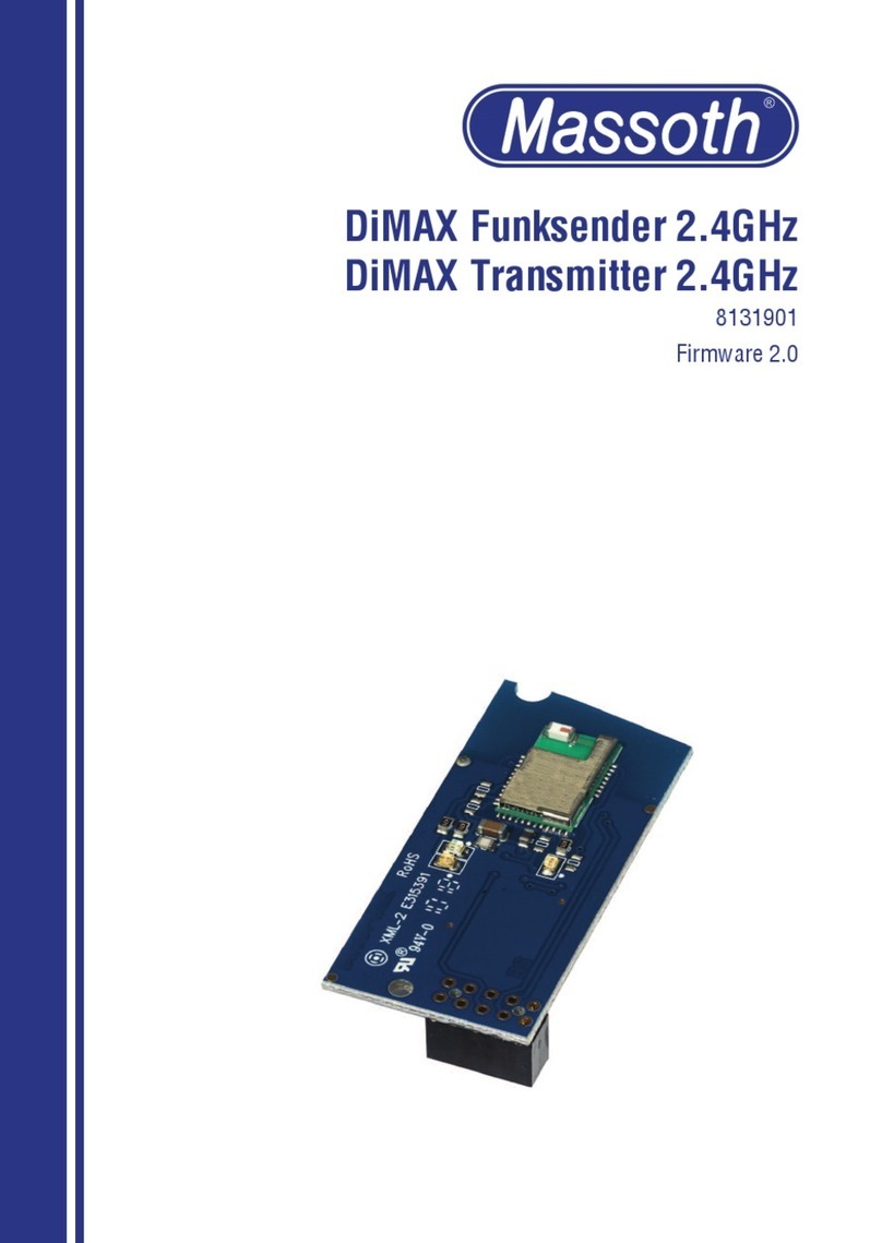
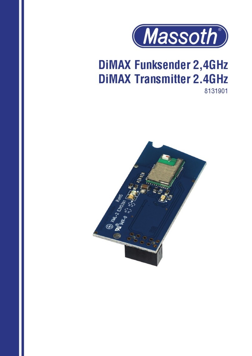
Massoth DiMAX Feedback transmitter User manual

DiMAX Rückmeldesender
DiMAX Feedbacktransmitter
Art.-Nr. / Item No.: 8133701/8132701
Version 1.0

2
1. Einleitende Information
Der DiMAX Funk-Rückmeldesender
erweitert das DiMAX Rückmeldemo-
dul 280R zum Funkrückmelder. Der
bidirektionale Funkbetrieb ermöglicht
im Freilandbetrieb Reichweiten bis ca.
100 Meter. Innerhalb von Gebäuden
können Reichweiten bis zu 50 Meter
erreicht werden. Somit kann man sich
die Verlegung von Buskabeln im Garten
ersparen. Der Rückmelder benötigt
mindestens einen Firmwarestand
von Version 2.0. Für den Betrieb wird
der DiMAX Funkempfänger (Art.-Nr.:
8133001/8132001) vorausgesetzt.
1.1 Lieferumfang
Funksendemodul
Antenne zum Einstecken
Bedienungsanleitung mit
Bohrschablone
2. Wichtige Informationen
zur Inbetriebnahme
Bauen Sie die Elektronik sorgfältig
nach den Anschlußplänen ein. Wer-
den beim Einbau Kabel vertauscht
oder Kabel kurzgeschlossen, kann
dies zur Zerstörung der Elektronik
führen.
Das Modul darf nur für die in der An-
leitung genannten Funktionen genutzt
werden. Ein anderweitige Verwen-
dung, kann zur Zerstörung führen.
•
•
•
•
•
1. General Information
The DiMAX Feedback transmitter
expands the DiMAX Feedback module
280R to a feedback signalling unit. Its
bidirectional radio operation allows
ranges of as much as 100 meters in
eld operation and you can achieve
ranges of as much as 50 meters within
buildings. That means that you do not
have to lay bus cables in the garden.
The feedback module needs at least
rmware version 2.0. The DiMAX radio
receiver (Item No. 8133001/8132001)
is required for operation.
1.1 Scope of Supply
the feedbacktransmitter
the plug-in antenna
the operating instructions
including the drill jig
2. Important information
for Starting Up
Carefully install the electronic equip-
ment according to the connection
diagrams. The electronic equip-
ment can be destroyed if cables
are confused or short-circuited at
installation.
The module may only be used for the
functions specied in the instructions
and any other usage may destroy the
module.
•
•
•
•
•

3
Die verwendete Funktechnik kann
empndlich auf statische Aua-
dungen reagieren. Beim Einbau des
Senders sollten Sie sich vorher an
einem metallischen Gegenstand (z.B.
Heizkörper) entladen. Fassen Sie im
Betrieb die Sendeantenne nicht an.
ACHTUNG: Bei starken Funkstörungen
können trotz mehrfacher Sendever-
suche Rückmeldedaten verloren
gehen. Die Firma Massoth übernimmt
keine Haftung für Folgeschäden auf-
grund gestörter Verbindungen!
3. Anschluss und Einbau
Öffnen sie das Rückmeldemodul
mit den 4 Schrauben im Boden und
nehmen sie den Deckel ab. Stecken
sie den Funksender wie in Abbildung
1 auf die 10-polige Stiftleiste. Die An-
tennenhülse wird gleichzeitig rechts
in die Kunststoffhülse gesteckt.
Schneiden Sie aus der letzten Seite
der Anleitung unsere Bohrschablone
heraus. Legen Sie diese wie abgebil-
det in die Innenseite des Gehäuse-
oberteils und bohren das markierte
Loch mit einem 1,5 mm Ø Bohrer.
Setzen Sie nun den Deckel wieder auf
und schrauben ihn fest. Stecken Sie
dann die Antenne durch die Bohrung
in den Antennenhalter.
•
•
•
•
The radio equipment used may react
sensitively to static charges.
You should be discharge any charge
you may have on a metallic object
(such as a heater) before installing
the transmitter. Do not touch the
sending aerial in operation.
CAUTION: Feedback data may be lost
if there is substantial radio interfer-
ence in spite of several attempts to
transmit. Massoth shall not assume
any liability for consequential damage
due to interference in connections.
3. Hook-Up
Open the feedback module with the
4 screws on the bottom and remove
the cover. Insert the transmitter onto
the 10-pole plug connector as shown
in illustration 1. The antenna bush
is simultaneously inserted into the
plastic bush on right-hand side.
Cut out our drilling jig from the
last page of the instructions, lay it
onto the inside of the upper part of
the housing as shown and drill the
marked hole with a 1.5 mm Ø drill.
Now put the cover on again and
screw tight. Then insert the antenna
into the antenna holder through the
hole.
•
•
•
•

4
Abbildung 1: Einbau des Rückmeldesenders
Illustration 1: Hook-up the feedbacktransmitter
Abbildung 2: Einlegen der Bohrschablone zum Bohren
Illustration 2: Drilling jig alignment for drilling

5
3.1 Einstellung
Vor der Inbetriebnahme muss das
Rückmeldemodul programmiert wer-
den. Grundlagen zur Programmierung
entnehmen sie bitte der Anleitung des
Rückmelders.
CV100 : Frequenzband
(0=Europa, 1=Nordamerika)
CV101 : Funkkanal (1..4)
Dieser muß identisch mit dem Emp-
fängerkanal sein.
CV102 : ID-Nummer (1..8)
Jede ID darf nur einmal vergeben
werden (Funk-Navigatoren beachten)
3.2 Update älterer
Rückmeldemodule (Version 1.x)
Den Updatele für das Rückmeldemodul
nden sie im Downloadcenter
www.massoth.de
Nach dem Update müssen vor der
Inbetriebnahme ein paar neue CV‘s auf
Grundeinstellung oder den von ihnen
gewünschten Wert gebracht werden :
CV50 = 20
CV100 = 0 (europ. Funk-Frequenz)
CV101 = 1
CV102 = 4
•
•
•
•
•
•
•
3.1 Adjustment
The feedback module has to be pro-
grammed before putting it into service.
Please nd the fundamentals for
programming in the instructions for the
feedback signalling unit.
CV100 : frequency band
(0=Europe, 1=North America)
CV101 : radio channel (1..4)
This should be identical to the
receiver channel.
CV102 : ID number (1..8)
You may only assign each ID once
only (see the R/C Navigators)
3.2 Updating older
feedback modules (Version 1.x)
You can nd the update le for the
feedback module in the download centre
at www.massoth.de.
A couple of new CV‘s have to put into
the basic setting or to the value you
want after the update and before putting
it into service:
CV50 = 20
CV100 = 0 (EU radio frequency)
CV101 = 1
CV102 = 4
•
•
•
•
•
•
•

6
4. Technische Daten
Spannungsversorgung: 3,3V
(über Rückmeldemodul)
max. Stromaufnahme: 30mA
Frequenzbänder: 433MHz (Europa),
915MHz (Nordamerika)
Sendeleistung: 9,8 mW
Betriebstemperatur: 0 - 45 °C
4.1 Garantie, Reparatur und
Kundendienst
MASSOTH gewährt die Fehlerfreiheit
dieses Produkts für ein Jahr. Die
gesetzlichen Regelungen können in
einzelnen Ländern abweichen.
Verschleißteile sind von der
Garantieleistung ausgeschlossen.
Berechtigte Beanstandungen werden
kostenlos behoben. Für Reparatur- oder
Serviceleistungen übergeben Sie das
Produkt bitte Ihrem Fachhändler oder
senden es direkt an den Hersteller.
Unfrei zurückgesendete Sendungen
werden nicht angenommen. Eine Kopie
des Kaufbelegs wird vorausgesetzt. Für
Schäden durch unsachgemäße
Behandlung oder Fremdeingriff oder
Veränderung des Produkts besteht kein
Garantieanspruch. Der Anspruch auf
Serviceleistungen erlischt unwiderruf-
lich. Irrtümer und Änderungen vorbehal-
ten. Auf unserer Internetseite nden Sie
die jeweils aktuellen Broschüren,
Produktinformationen, Dokumentation
und Softwareprodukte rund um
MASSOTH-Produkte.
•
•
•
•
•
4. Technical specications
Voltage supply: 3.3 V
(over the feedback module)
Maximum power consumption: 30mA
Frequency bands: 433 MHz (Europe),
915 MHz (North America)
Transmitter power: 9.8 mW
Temperature range: 0 - 45°C
(-4°F to 113°F)
4.1 Warranty, Repair and
Customer Service
MASSOTH warrants this product against
defects in materials and workmanship
for one year from the original date of
purchase. Other countries might have
different legal warranty situations.
Normal wear and tear, consumer
modications as well as improper use
or installation are not covered. Periph-
eral component damage is not covered
by this warranty. Valid warranty claims
will be serviced without charge
within the warranty period. For warranty
service please return the product to
you dealer or send it directly to the
manufacturer. Return shipping charges
are not covered by MASSOTH. Please
include your proof of purchase with the
returned goods. Errors and changes ex-
cepted. Please check our website for up
to date brochures, product information,
documentation and software updates.
•
•
•
•
•

7
Dieses Produkt entspricht den CE Konformitätsrichtlinien für elek-
trische Kleingeräte in der aktuellen Fassung.
This unit conforms to the CE Standards
RoHS
Dieses Produkt ist nach den aktuellen EG Richtlinien umgangssprach-
lich „bleifrei“ hergestellt und damit RoHS-konform.
This unit is manufactured according to the latest EG Standards for
lead free manufacturing conforming to RoHS Standard.
Entsorgen Sie das Produkt nicht im Hausmüll. Nutzen Sie bitte den
dafür vorgesehenen Elektroschrott.
Please dispose of according to your State regulations.
Werfen Sie das Produkt nicht in offenes Feuer oder durch Hitze
entammbare Brennstoffe.
Do not dispose of in open re.
4.2 Hotline
Serviceanfragen richten Sie bitte an:
Massoth Elektronik GmbH
Mo 14:00-17:30 sowie Do 8:00-12:00
FON +49 (0)6151-35077-38
FAX +49 (0)6151-35077-44
4.2 Hotline
For technical support contact:
Massoth Elektronik GmbH, Germany
Mo 2:00-5:30 p.m. Thu 8:00-12:00 a.m.
FON +49 (0)6151-3507738
FAX +49 (0)6151-3507744
Massoth Electronics USA
6585 Remington Dr. Suite 200
Cumming, GA 30040
9:00 a.m. to 4:00 p.m. EST Mo thru Fr
Ph. +1 770-886-6670
Fax +1 770-889-6837
032376o

8

9

10
Bohrschablone für Antennenbohrung im Deckel des Rückmelders
Drilling jig for top cover antenna shaft hole

11

MADE
IN
GERMANY
Massoth Elektronik GmbH
Frankensteiner Str. 28 · D-64342 Seeheim · Germany
FON: +49 (0)6151-35077-0 · FAX: +49 (0)6151-35077-44
813x701_0410_ML
This manual suits for next models
2
Table of contents
Other Massoth Transmitter manuals