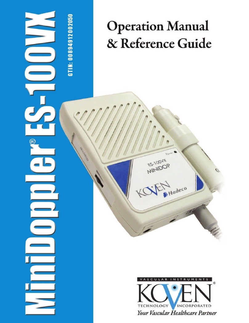
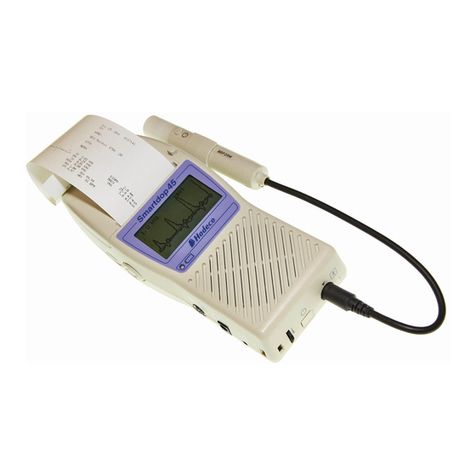
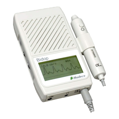
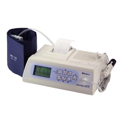
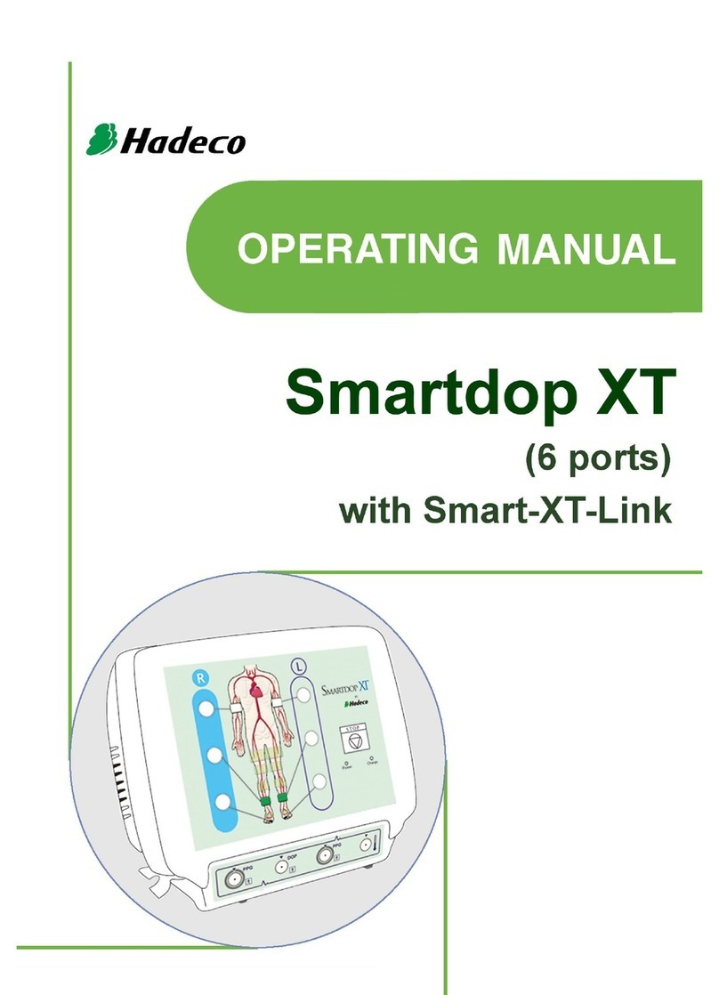
Hadeco Smartdop XT6 User manual

Smartdop XT6
Quick-Start Guide

Specifications:
Power: Ni-MH rechargeable battery pack & AC adaptor
Full charge life: Approx. 2 hours
Battery life: Approx. 2 years
Speaker output: 250 mW or more
Measurement range: 30 to 260 mmHg
Dimensions: 300 (W) x 244 (H) x 167 (D) mm
Weight: Approx. 3.6 kg
Electrical safety: Conforms to IEC-60601-1
Options: Additional Cuffs, Temperature probe
Computer System Requirements:
OS: Windows XP/ Vista/ 7/8/10
CPU clock: Celeron 1 GHz or more
Display: 800 x 600 dots or more
256 colors or more
Minimum memory requirements:
RAM: 1 Gbytes or more
HD: 40 Mbytes or more
Software is NOT compatible with Apple Mac operating systems unless using Parallels or similar software.
Thank you for purchasing the Hadeco Smartdop XT6 Fully Automatic Vascular Testing System.
This guide has been created as a quick reference guide in relation to operating your Smartdop XT6
and Smart-XT-Link software on your Windows based PC or Tablet.
If you encounter any issues not addressed within this document, refer to the pdf manual which can be found on the soft-
ware disc supplied.
© Copyright Briggate Medical Company 2018 - No parts of this document either written or images may be reproduced without permission.

4MAIN FEATURES & CONTROLS
5SMARTXTLINK SOFTWARE INSTALLATION
6OBTAINING STANDARD ABI/TBI
8STANDARD DOPPLER VELOCITY WAVEFORMS
9DOPPLER WAVEFORMS INTERPRETATION
10 PRINTING & SAVING REPORTS
11 FOOT TEMPERATURE PROBE
3
INDEX

MAIN FEATURES & CONTROLS
For a more detailed explanation on the Features and Controls for the Smartdop XT6, please refer to the
Manufacturers Operating Manual supplied with the device.
1. Inflation ports for Right side To connect extender tubes for Right side cuffs
2. Inflation ports for Left side To connect extender tubes for Left side cuffs
3. PPG Probe connector for Right side To connect PPG Probe for Right toe
4. 8 MHz Probe connector To connect 8 MHz Probe
5. PPG Probe connector for Left side To connect PPG Probe for Left toe
6.Foot Temperature Probe connector To connect Temperature Probe (optional extra)
7. Stop Button To stop testing and dump all cuffs immediately while in measurement
8. Charge Indicator Indicates battery charging status
9. Power Indicator Indicates Power Status and Battery Level
10. Probe Holders To hold Probes when not in use
1.
2.
3. 4. 5. 6.
7.
8.
9.
10.
4

11.
12. 13. 14.
For a more detailed explanation on the Features and Controls for the Smartdop XT6, please refer to the
Manufacturers Operating Manual supplied with the device.
11. Speaker For waveform audio output
12.Power Switch ON/OFF To turn the device ON and OFF
13. AC Adapter connection To be be connected to Mains Power supply
14. Serial USB Port To connect to Windows based PC
MAIN FEATURES & CONTROLS
SMART-XT-LINK SOFTWARE INSTALLATION
The Smartdop XT6 CAN ONLY BE OPERATED VIA THE SMART-XT-LINK SOFTWARE.
Please refer to the sections titled “3.Getting Started (pg 6)” and “4.Testing (Pg 8)” in the pdf manual supplied on the USB Flash Drive
for instructions for software installation and initial set-up of the device.
5

RL
RL
R
PPG PPG
L
(1) Open the Smart-XT-Link software and enter
“Automatic Arterial Testing” from the Main Menu.
(2) Wrap cuffs snugly, positioning bilaterally for arm, ankle and hallux.
OBTAINING STANDARD ABI/TBI
6

OBTAINING STANDARD ABI/TBI (cont...)
(3) Hook up colour coded tubing between cuff and inflation port on the XT6 for each site being used. Be sure to match colour coded tub-
ing with the same colour inflation port for each site. Left & Right tubing and inflation ports are also colour coded with blue rubber secured
on the end of each “Right” tube, while a blue strip on the device identifies all “Right” inflation ports (see pictured at end of manual).
(4) Connect 2 PPG probes to the Smartdop XT6 and secure each PPG transducer with the clear side against the pad of each great toe.
You can use either the Toe Clips provided or Micropore tape to secure the probes.
(5) Once all cuffs and probes are secured in place, click
“Auto Start”. The Smartdop XT6 will start on both sides simultaneously, going
through each selected site individually. Once complete,
the message shown on right will appear. Click OK to close it and
ABI and TBI will be calculated automatically during the tests.
Please Note: If for some medical reason one arm site cannot be tested (i.e. dialy-
sis), simply leave the cuff off the site and complete auto testing. An error message
will appear, click ignore and the results will appear.
(6) If a site fails, the message shown on right will appear,
explaining which site has failed. Simply adjust the cuff, ensure all
tubing is tightly secured and click “Yes” to retry or “Ignore” to skip
the site and carry on with procedure.
Once complete, click “Return to Main Screen”.
7

90º
60º
(1) Enter “Doppler Arterial Testing”. This screen should already be set up
with the necessary sites from your Initial Set Up process.
(Refer to Initial Set-Up Manual)
(2) Connect 8Mhz probe to Smartdop XT6 and have doppler gel ready.
(3) Click on any individual site and a Monitoring Screen will appear,
ready to detect a waveform.
(4) Palpate relevant pulse and apply doppler gel.
(5) Position probe on pulse and angle at approximately 60 degrees to the vessel. Adjust the
probe angle until clear, crisp sounds are heard and a
defined waveform is visible on the Smart-XT-Link Software.
(6) Once you have found an ideal waveform, use “Freeze” button on the
probe. If you are unsatisfied with current waveform, press “Freeze” button
on the probe again to continue searching for an ideal waveform.
STANDARD DOPPLER VELOCITY WAVEFORMS
(7) Once you have an ideal waveform identified on the Monitoring Screen, click “Decision” to save
waveform and click “Return”.
(8) Repeat previous step across all required sites.
8

DOPPLER WAVEFORMS - INTERPRETATION
TRIPHASIC (Normal)
• Triphasic sounds indicate bi-directionality and a compliant artery at the point of probe contact.
• The first long sound is the systolic forward component.
• The second short sound is the reversal component and is seen below the baseline
of the waveform print out. It is thought to occur upon closure of the aortic valve.
• The third sound indicates wall motion characteristic of a compliant artery.
BIPHASIC (Normal to Mild PAD)
• Biphasic sounds indicate bidirectional flow velocity having both forward systolic
and reverse diastolic component but no third component.
• While they are considered normal, the lack of the third component may indicate minor to
moderate blood flow impairment or simply improper probe angle this is why it is important to
carefully adjust the probe to obtain the best sounds.
MONOPHASIC (Severe PAD)
• Monophasic sounds are low frequency sounds having a single cycle.
They are low in intensity and indicate severe disease.
ABI
Ankle Brachial Indexes provide quantitative
measurements of peripheral circulation.
However, elevated readings >1.3 are common
with patients with diabetes due to calcification
of the vessels which results in an invalid
reading.
ABI = ankle systolic blood pressure
brachial systolic blood pressure
TBI
Toe Brachial Indexes are now commonly used as the chance of an invalid reading
due to calcification of the vessels is less likely when compared with ankle pressures.
TBI = toe systolic blood pressure
brachial systolic blood pressure
Peripheral arterial disease (PAD) <0.9
Mild PAD 0.7-0.9
Moderate PAD 0.4-0.69
Severe PAD <0.4
Normal 0.65-1
Severe/Critical PAD <0.2
Absolute Toe Pressures
Absolute toe pressures are also used to indicate wound healing potential.
Absolute toe pressures >30mmHg indicate there is an increased chance of healing.
These quantitative measurements can assist in establishing a baseline to track a
patient’s progress over time, as well as being an excellent screening tool to identify
potential foot health risk.
Reference: International Working Group on the diabetic foot, 2011
9

(1) Once all waveforms are taken, click “Print”.
(2) Select pages you wish to include in patient report (Automatic
Arterial Testing & Doppler Arterial Testing).
(3) Click “Preview” to ensure the report includes pages you require.
(4) If you wish to print your patient report, select printer you wish
to use and click “Print”.
(5) If you wish to save your patient report as PDF, click “PDF”. Se-
lect folder you wish to save patient report PDF’s and click “Save”.
(6) To start process again for new patient, Return to Main Screen
and click “New File”. You can also load existing files by clicking
“Search Files”.
PRINTING & SAVING REPORTS
Example of a Patient Report:
10

FOOT TEMPERATURE PROBE - SOLD SEPARATELY
The Smartdop XT also has the ability to conduct Foot Temperature studies via the optional Themometer Probe.
For instructions on the procedure, please refer to page 21 of the pdf manual supplied on the software USB Flash Drive.
For pricing on the device, please contact Briggate Medical.
11

* Tablet not included
23-25 Lakewood Blvd
Braeside Vic 3195
Australia
Ph: (03) 8586 7800
Fax: (03) 8586 7888
briggate@briggate.com.au
www.briggatemedical.com
Table of contents
Other Hadeco Medical Equipment manuals
Popular Medical Equipment manuals by other brands

Drive
Drive 15302LW Owner's assembly and operating manual

Exsurco Medical
Exsurco Medical Amalgatome MD Quick reference guide

Otto Bock
Otto Bock 1S101 SACH+ Instructions for use

Bio Compression Systems
Bio Compression Systems SC-2004 operating instructions

Acteon
Acteon ImplantCenter M+ user manual

Asskea
Asskea M20 Plus instruction manual