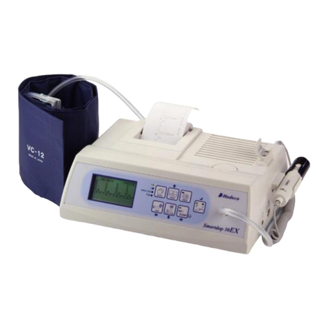
Hadeco Smartdop 30EX User manual

GTIN: 00894912002098

CAUTION Use the Smartdop®30EX under normal operating conditions, according to the instructions
provided in this operation manual and under the operating conditions stated in the product
specications.
CAUTION Federal law restricts this device to sale by or on the order of a licensed healthcare
practitioner.
CAUTION The Smartdop®30EX has not been evaluated for safety and compatibility in the MR
environment. The Smartdop®30EX has not been tested for heating or migration in the MR
environment.
CAUTION Perform ultrasound testing/procedures prudently using the principle of ALARA (As Low As
Reasonably Achievable).
CAUTION Use only the designated adaptor that came with your Smartdop®30EX or contact Koven
Technology for parts & accessories.
CAUTION To avoid possible damage to the printer, never pull paper in the opposite direction as the
paper feed. To properly remove paper, cut the paper at the roll side and pull the remaining
paper out through the top of the unit.
CAUTION Use ultrasound gel. Other materials such as baby oil or cream may produce incorrect
sounds or damage the probe.
WARNING The ultrasound gel included with purchase is non-sterile and should only be used
noninvasively.
WARNING Discontinue use of ultrasound gel if an allergic reaction occurs.
CAUTION The probe transducer tip is thin and delicate. Please handle with care and use the probe cap
when not in use.
WARNING If any abnormality is found on the unit or patient, discontinue use in a manner safe to the
patient.
WARNING In case of emergency or unexpected situations, stop cu ination by pressing the INF/DUMP
button on the front panel, disconnect the tubing from the unit, and turn the unit o.
CAUTION Make sure all cables are property connected and there are no obstructions to any external
connections to the patient, before use.
CAUTION Do not drop or place in an area where the unit may fall.
CAUTION Do not use simultaneously with an electrocautery debrillator, other ultrasonic device or a
mobile phone.
CAUTION Do not use in an area where a strong electromagnetic eld is present. Doing so may cause
incorrect measurements.
CAUTION Do not place near water or other liquid, where atmospheric pressure, temperature, humidity,
ventilation, sunlight, dust, salt sulfur, etc. may cause damage or where chemicals are stored
or gas may be generated.
CAUTION Protect the unit from vibration and shock during transport.
WARNINGS & CAUTIONS

CAUTION Do not use excessive force when disconnecting cables.
CAUTION Use only designated Smartdop® 30EX accessories.
CAUTION The Doppler box should not have direct contact with the patient or be placed in the sterile
area. The Doppler box cannot be sterilized or reprocessed.
WARNING The Doppler box and noninvasive probes should be cleaned following any patient contact.
CAUTION Do not submerge the Doppler box or probe in any liquid.
CAUTION Clean probes with a recommended probe cleaner before use.
CAUTION Do not perform any modications to the unit.
CAUTION Repairs should only be performed by authorized personnel.
WARNINGS & CAUTIONS

TABLE OF CONTENTS
Warnings & Cautions
SECTION 1 (Basic Operation)
Introduction ...................................................................................................................1
Features ..........................................................................................................................1
1. Indications for Use, Contraindications, & Applications
1-1 Detection of Arterial and Venous Blood Flow Velocity ..........................................2
1-2 PPG & PV Arterial & Venous Studies....................................................................2
2. Waveform Pattern Analysis
2-1 Doppler Arterial Waveforms .................................................................................3
2-2 Pulse Volume Arterial Waveforms .........................................................................4
3. Controls
3-1 Front View .............................................................................................................5
3-2 Operation Panel .................................................................................................6-7
3-3 Right Rear View & Probe ......................................................................................8
4. Setup & Basic Operation
4-1 Turning the Unit ON / OFF ....................................................................................9
4-2 Checking the Battery Level .................................................................................10
4-3 Charging the Battery ..........................................................................................10
4-4 Installing the Printer Paper.................................................................................. 11
4-5 Measuring Blood Velocity...............................................................................12-13
5. Mode & Menu Settings
5-1 Basic Mode Settings ...........................................................................................14
5-2 Other Modes
5-2-1 Measurement / Freeze Mode .....................................................................14
5-2-2 Display Mode..............................................................................................14
5-3 Menu
5-3-1 Menu Operation..........................................................................................15
5-3-2 Menu for Blood Velocity Measurement Mode.............................................16
5-3-3 Menu for Blood Velocity Freeze Mode .......................................................17
5-3-4 Menu for Pressure Mode (Measurement & Freeze) ...................................18
5-3-5 Menu for PPG (Photoplethysmography)(Measurement & Freeze) ............19
5-3-6 Menu for PV-AC (Pulse Volume Arterial) Mode (Measurement & Freeze) ...20
5-3-8 MEMORY-STORE ......................................................................................21
5-3-9 MEMORY-READ ........................................................................................22
5-3-10 MEMORY-CLEAR ...............................................................................22-23
5-3-11 DIR (ow direction) ...................................................................................23
5-3-12 DISP / OTHERS-DISP (Waveforms/Data) ...............................................24

TABLE OF CONTENTS
5-3-13 WAVEFORM ..................................................................................................25
5-3-14 OTHERS-LANGUAGE...................................................................................26
5-3-15 OTHERS - PRB-KEY .....................................................................................26
5-3-16 OTHERS - CALIBRATION .............................................................................26
5-3-17 OTHERS - CAL PRINT (Printing Calibration)......................................................27
5-3-18 OTHERS - BACKLIGHT ................................................................................27
5-3-19 OTHERS - AUTO OFF ...................................................................................27
5-3-20 OTHERS - RESET .........................................................................................28
5-3-21 OTHERS - DISCHARGE ..........................................................................28
5-3-22 GUIDANCE ..............................................................................................29
5-3-23 CURSOR ..................................................................................................29
5-3-24 P.DISPLAY................................................................................................29
5-3-25 P.CLEAR ..................................................................................................30
5-3-26 COUNT .....................................................................................................30
5-4 Shortcut Keys ...........................................................................................................31
6. LCD Display
6-1 Blood Velocity Modes
6-1-1 Waveforms .................................................................................................32
6-1-2 Numerical Data...........................................................................................32
6-2 Pressure Modes (Arm/Leg and Toe Modes)
6-2-1 Display Samples.........................................................................................33
6-2-2 Error Messages ..........................................................................................34
6-3 Battery Indicators
6-3-1 Battery Level Indicator................................................................................34
6-3-2 Low Battery Indicator..................................................................................34
6-4 PV-AC (Pulse Volume Arterial)............................................................................34
7. Printing Waveforms & Data
7-1 How to Print ........................................................................................................35
7-2 Print Samples.................................................................................................36-37
7-3 Numerical Velocity ..............................................................................................38
7-4 4-Step Calibration ...............................................................................................38
8. External Outputs
8-1 Headset...............................................................................................................39
8-2 Communication Port ...........................................................................................39
9. Maintenance ...........................................................................................................39
10. Symbol List ............................................................................................................40
11. Operating Principles ..............................................................................................41
12.Block Diagram .......................................................................................................42

13.Specications .........................................................................................................43
14.Operation, Storage & Transport Environments ...................................................44
15.System Includes .....................................................................................................44
16.Cleaning ..................................................................................................................45
17.Disposal of Device ..................................................................................................46
18.Warranty ..................................................................................................................46
19.Safety Standards ...............................................................................................47-49
SECTION 2 (Testing Instructions)
1. Ankle Brachial Index .........................................................................................50-53
2. Segmental Blood Pressures ...........................................................................54-56
3. Venous Compression Studies ..............................................................................57
4. PPG Toe Pressures & Toe Brachial Index (TBI) .............................................58-60
5. PPGVenousReux ...........................................................................................61-62
6. Pulse Volume recordings (PVRs) .........................................................................63
TABLE OF CONTENTS

Section1
Section1
Basic Operation

Thank you for choosing the
Smartdop®30EX…
e Smartdop® 30EX is a bidirectional Doppler with LCD display, integrated printer
and automatic cu inator. It is used for the detection of arterial and venous blood
ow in extremities. Please read this manual carefully to acquaint yourself with the
proper operation.
Smartdop and Smart-V-Link are registered trademarks ® of Koven Technology, Inc.
FEATURES
• BidirectionalDopplerwithLCD,cuinator,&integratedprinter
Displays and prints velocity waveforms and numerical data
Automatic cu ination / deation
Automatically calculates and prints ABI / TBI and velocity / pressure
• Convenient probe activation button
Freezes and/or prints waveform and numerical data for documentation purposes
Inates and/or dumps the cu
• Automatic Power “OFF”
To conserve battery life
• USB computer interface & optional software
Transfers waveforms and numerical data to a computer for data storage & EMR’s
USB communication cable and Smart-V-Link®software are optional
• 30 Waveform Memory
Save patient waveforms and numerical data for later use or download to the optional Smart-V-Link®software
• Optional PPG (Photoplethysmography) probe available for expanded arterial and
venous testing
NOTE
If using the Smartdop®30EX with the optional Smart-V-Link®documentation software, please
refer to the Smart-V-Link®operation manual for instructions on downloading waveforms and
performing tests with the Doppler and software.
Manufactured by:
Hadeco, Inc.
2-7-11 Arima, Miyamae-ku, Kawasaki, 216-0003 Japan
CAUTION
Use the Smartdop®30EX under normal operating conditions, according to the instructions
provided in this operation manual and under the operating conditions stated in the product
specications.
CAUTION
Federal law restricts this device to sale by or on the order of a licensed healthcare practitioner.
RX only.
CAUTION
The Smartdop®30EX has not been evaluated for safety and compatibility in the MR environment.
The Smartdop®30EX has not been tested for heating or migration in the MR environment.
CAUTION
Perform ultrasound testing/procedures prudently using the principle of ALARA (As Low As
Reasonably Achievable).
1

Smartdop®30EXBasicOperation
1. INDICATIONS FOR USE, CONTRAINDICATIONS, &
APPLICATIONS
INDICATIONS FOR USE
The Smartdop® 30EX intended for use in the noninvasive evaluation of peripheral vascular
pathology in patients by detecting arterial and venous blood ow in extremities.
CONTRAINDICATIONS
Not intended for use in ophthalmic or periorbital studies as the acoustic intensity is higher than
the level recommended for use on and around the eye.
APPLICATIONS
(Refer to section 2 for Noninvasive Arterial & Venous testing instructions)
1-1 DOPPLER ARTERIAL & VENOUS APPLICATIONS
• Ankle Brachial Index (ABI) studies • Systolic pressures
• Peripheral vascular procedures • Blood ow velocity
• Segmental Pressure studies • Penile & digit systolic pressures
• Venous compressions
1-2 PPG (PHOTOPLETHYSMOGRAPHY) AND PULSE VOLUME (PV) ARTERIAL &
VENOUS APPLICATIONS
(PPG applications require the optional PG-21 Photoplethysmography probe, supplied
separately)
• PPG toe pressures & Toe Brachial Index (TBI)
• PPG venous reux
• Pulse Volume Recordings (PVR)
2
NOTE
The Smartdop®30EX has built-in
pulse volume capabilities. No
additional PV module is required
to perform pulse volume arterial
studies.
NOTE
The Smartdop® 30EX and associated Doppler probes, cus, and photoplethysmography
(PPG) probe are not intended to be placed in contact with blood or mucous membranes.
NOTE
The Smartdop®30EX is not recommended for fetal use.

Smartdop®30EXBasicOperation
2. WAVEFORM PATTERN ANALYSIS
2-1 DOPPLER ARTERIAL WAVEFORMS
The Doppler arterial waveforms obtained from the lower extremity may be classied into six
categories as an aid in interpretation.
TYPE TYPICAL WAVEFORM FINDINGS
0 The contour exhibits a steeply rising upslope at the onset of systole,
rapid systolic downslope, and reverse ow (below baseline). Dop-
pler sounds are loud and sharp. Normal peak forward velocity = 30
+/- 10 cm at the dorsalis pedis artery.
I The contour demonstrates a strong but diminished systolic compo-
nent and loss of reverse ow. The width of systolic pulse is broad-
ened. The Doppler sounds are diminished very little as compared
to the type “O” pattern.
II The contour shows prolongation of both the upstroke and the down-
stroke and diminished waveform amplitude (attening). Doppler
sounds are heard during systole and continuing through all or most
of diastole.
III The contour exhibits slowly rising velocity during systole, and the
amplitude of the waveform is reduced. Doppler sounds are not
sharp even during systole.
IV The amplitude of the waveform and the Doppler sounds is greatly
reduced.
V The amplitude of the waveform is extremely reduced. The contour
is hardly recognizable as an arterial blood ow waveform. The
Doppler sounds are very faint.
3

Smartdop®30EXBasicOperation
4
2. WAVEFORM PATTERN ANALYSIS
2-2 PULSE VOLUME ARTERIAL WAVEFORMS
A normal Pulse Volume arterial waveform will display a rapid rise
in the upstroke during systole and a sharp peak at maximum
amplitude, followed by a gradual downstroke following peak
amplitude, and usually the presence of a dicrotic notch.
The rst sign of possible abnormality is the absence of
the dicrotic notch. More signicant occlusions will show a
decreased slope of the ascending and descending segments,
and a rounding of the systolic peak occurs. More serious obstructions will show attened
waveforms.
It is important to note that arteries located lower on the leg will produce sharper waveform
peaks, while those located higher on the leg will produce more rounded waveforms.
Brachial
Thigh
Below Knee
Ankle
Typical Normal Waveform Typical Abnormal Waveform
NOTE
PV waveforms are quantied in changes of mmHg, this is not a systolic pressure or an exact
quantication.

Smartdop®30EXBasicOperation
3. CONTROLS
3-1 FRONT VIEW
1) PRINTER To print waveforms, systolic pressures,
ABI/TBI and velocity/pressure documentation.
2) SPEAKER Outputs Doppler sounds.
3) VOLUME CONTROL To adjust sound volume.
4) PROBE HOLDER 1 For probe placement when not in use.
5) PROBE HOLDER 2 For probe placement when not in use.
6) INFLATION INLET To connect the tubing for the blood pressure cu.
7) LCD DISPLAY Displays waveform, numerical data and menu for
mode settings.
5

Smartdop®30EXBasicOperation
3. CONTROLS
3-2 OPERATION PANEL
1) MODE LEDs Indicates the mode selected.
(Mode 1, Mode 2, Arm/Leg, Toe)
Illuminates sequentially while the battery is charging.
2) MODE BUTTON To select the mode -
Mode 1 (Arterial), Mode 2 (Venous), Arm/Leg
Pressure, Toe Pressure. See 5-1 “BASIC MODE
SETTINGS” for details.
3) PRINT BUTTON To activate / deactivate the printer.
Menu mode: Moves the cursor up.
4) MENU BUTTON To enter Menu mode. See 5-3 “MENU” for details.
+ Turns the backlight ON/OFF.
5) PROBE SELECTION To select the probe intended for use from the connected
BUTTON probes. The LED corresponding to the probe number
will illuminate.
To select PV Arterial mode (both LED’s will be lit).
Menu mode: Sets and/or changes the mode or
setting.
Freeze mode:
View next memory number.
+ View previous memory number.
6

Smartdop®30EXBasicOperation
6) INF/DUMP (FREEZE) To inate the cu or stop ination and dump the blood
BUTTON pressure cu (Arm/Leg and Toe modes).
To freeze / unfreeze the waveform (measurement
mode).
Menu mode: Moves the cursor right and changes
the mode or setting.
+ Moves the systolic pressure point to the right
See 5-3-23 “CURSOR” for details.
7) LEG/TOE BUTTON To store and display leg and/or toe pressures (freeze
mode).
Press less than 1 second to display the ABI or TBI
(Arm/Leg or Toe modes during measurement).
Press longer than 2 seconds to erase pressure
values (Arm/Leg or Toe Modes).
To change the display mode: Waveform / Numerical
(Mode 1 or Mode 2 during measurement). See 5-2-2
“Display Mode” for details.
Menu mode: Moves the cursor down.
+ Magnies the waveform on the LCD
See 5-3-13 “WAVEFORM” for details.
8) ARM BUTTON To store and display the arm (brachial) pressure
(freeze mode).
Press less than 1 second to display the ABI or TBI
(Arm/Leg or Toe modes during measurement).
Press longer than 2 seconds to erase pressure
values (Arm/Leg or Toe modes).
Menu mode: To return to the previous menu or exit
Menu mode.
+ Moves the systolic pressure point to the left
See 5-3-23 “CURSOR” for details.
3. CONTROLS
7
Indicates that the mode button should be pressed and held down before pressing the indicated button
+

Smartdop®30EXBasicOperation
3. CONTROLS
3-3 RIGHT REAR VIEW
& PROBE
1) ROLL SHAFT To hold the paper roll in the printer.
2) COMMUNICATION To connect the Doppler to a computer.
PORT
3) PROBE CONNECTOR 1 To connect probe 1.
4) PROBE CONNECTOR 2 To connect probe 2. Use when connecting PPG or
additional probes.
5) AC ADAPTOR To connect the designated AC adaptor.
CONNECTOR
6) POWER SWITCH To turn the unit ON/OFF.
7) HEADSET To connect a headset (not provided). Cuts o sound
to the speaker.
8) PROBE Multi-probe selection: 5, 8 and 10 MHz.
9) PROBE BUTTON To freeze / unfreeze the waveform.
To activate / deactivate the printer.
To activate / deactivate the cu inator.
The probe button function is set in Menu mode under PRB-KEY.
See 5-3-15 “OTHERS-PRB-KEY” for details.
10)PROBE CAP To protect the probe transducer tip when not in use.
8
ON OFF

Smartdop®30EXBasicOperation
4. SETUP & BASIC OPERATION
4-1 TURNING THE UNIT ON / OFF
1. Connect the probe with the round probe
connection mark on the probe connector pointed up
(12 o’clock). Press the power button to turn the unit
ON.
Power ON:
Power OFF:
2. When the battery is low, a low battery indicator
appears in the bottom left corner of the LCD, as
shown in the illustration on the right. Although
the Smartdop®will continue to operate it is
recommended that the battery be recharged as
soon as possible.
See 4-3 “CHARGING THE BATTERY” for details.
3. AUTOMATIC POWER OFF
When the unit is not connected to the AC adaptor, it
will automatically shut o as indicated below:
• 15 minutes while in measurement mode
• 5 minutes when no signal is present
• 10 minutes while in freeze mode
Low battery indicator
9
Power switch
Probe connection mark

Smartdop®30EXBasicOperation
4-3 CHARGING THE BATTERY
Charge the battery before using the Smartdop®30EX for
the rst time.
1. Turn the Doppler o and plug in the AC adaptor.
2. The Mode LEDs will illuminate sequentially while
charging is in progress.
3. The charge process will stop automatically once
charging is complete. Disconnect the charger
before using the Doppler.
10
4. SETUP & BASIC OPERATION
4-2 CHECKING THE BATTERY LEVEL
1. Turn the unit on and press the MENU button to
display the Menu screen. The battery level indicator
is shown in the upper right corner of the Menu
screen.
2. The battery level indicator shows the battery level
in 4 stages, as shown in the illustration on the right.
3. Charge the battery when the indicator shows that
the battery level is low.
High
Medium
Low
Empty
Battery level indicator
AC adaptor connector
Mode LEDS
NOTE
It takes approximately 4 hours to fully charge
the battery. Battery life is approximately 300 full
charges. Contact Koven Technology, Inc. for
battery replacement.
NOTE
When the battery is extremely
low, the LCD display will not
operate and no sound will be
heard through the speakers.
Charge the battery.
NOTE
Periodically discharging the battery may help
prolong battery life. The battery DISCHARGE
option is available in the menu when the
AC adaptor is connected to the main unit. If
discharging the battery, please add several
hours to the charge time. See 5-3-21 “OTHERS-
DISCHARGE” for details.
CAUTION
Use only the designated adaptor that came
with your Smartdop®30EX or contact Koven
Technology for parts & accessories.

Smartdop®30EXBasicOperation
11
4. SETUP & BASIC OPERATION
4-4 INSTALLING THE PRINTER PAPER
1. Turn the Smartdop®30EX ON and set the MODE to
1 or 2.
2. Remove the paper roll shaft and set it into the
paper roll. Insert and hold the edge of the paper
into the paper entry slot located under the printer.
Press the PRINT button to activate the printer. The
paper will catch and feed through the printer.
3. When a sucient amount of paper has been fed
through, press the PRINT button again to stop the
printer . Pull the edge of the paper out a few inches
and tear o at the paper guide. Snap the roll shaft
with the paper into the roller guide.
NOTE
For problem free paper loading, cut the paper
straight before inserting it into the entry slot.
Apply slight ngertip pressure as the paper is
being fed into the slot.
CAUTION
To avoid possible damage to the printer, never pull
paper in the opposite direction as the paper feed.
To properly remove paper, cut the paper at the roll
side and pull the remaining paper out through the
top of the unit.

Smartdop®30EXBasicOperation
4. SETUP & BASIC OPERATION
4-5 MEASURING BLOOD VELOCITY
This section explains the fundamentals of using the
Smartdop® 30EX to measure blood velocity. For detailed
instructions on performing specic tests, see Section 2
Testing Instructions.
1. Connect the probe to the Smartdop®30EX with
the round probe connection mark on the probe
connector pointed up (12 o’clock position).
2. Press the power button to turn the unit on. Turn the
volume control to the desired level.
3. Press the MODE button to select Mode 1 for
arterial or Mode 2 for venous.
4. Place ultrasonic gel on the probe tip or the patients
skin. Make sure there is enough gel to cover the tip
of the probe.
5. Place the probe on the measurement area at an
angle of 45° to 60° against ow and adjust to locate
the best sounds.
12
Probe connection mark
Power switch
NOTE
Make sure the lighted LED on the probe selector
button corresponds to the probe connector being
used. Press the probe selector button to change
the probe selection.
CAUTION
Use ultrasound gel. Other materials such as baby
oil or cream may produce incorrect sounds or
damage the probe.
WARNING
The ultrasound gel included with purchase is non-
sterile and should only be used noninvasively.
WARNING
Discontinue use of ultrasound gel if an allergic
reaction occurs.
CAUTION
The probe transducer tip is thin and delicate.
Please handle with care and use the probe cap
when not in use.

Smartdop®30EXBasicOperation
13
4. SETUP & BASIC OPERATION
4-5 MEASURING BLOOD VELOCITY (cont.)
6. When the waveform becomes rhythmic and stable,
wait 5 seconds or more without moving the probe
on Mode 1 or 25 seconds or more on Mode 2.
Then, press the INF/DUMP button or probe button
(probe button function must be set to FREEZE or
FRZ&PRINT) to freeze the waveform.
7. To print the waveform, press the PRINT button or
the probe button (probe button function must be set
to PRINT or FRZ&PRINT).
8. To save the waveform and numerical data in
memory, see 5-3-8 “MEMORY-STORE” for
details.
9. Press the INF/DUMP button or the probe button to
exit freeze mode and return to measurement mode.
NOTE
The probe button function can be changed to
FREEZE only, PRINT only, or FRZ&PRINT. See 5-3-
15 “OTHERS-PRB-KEY” for details.
WARNING
If any abnormality is found on the unit or patient,
discontinue use in a manner safe to the patient.
WARNING
In case of emergency or unexpected situations,
stop cu ination by pressing the INF/DUMP button
on the front panel, disconnect the tubing from the
unit, and turn the unit o.
Other manuals for Smartdop 30EX
1
Table of contents
Other Hadeco Medical Equipment manuals
Popular Medical Equipment manuals by other brands

Elephant
Elephant SELF-HEALTH KIOSK user guide

Advanced Instruments
Advanced Instruments Anoxomat III Service guide

southpaw enterprises
southpaw enterprises Static Eye Bolt Wrap 7011 instruction sheet

Neurotech
Neurotech kneehab instruction manual

Verathon
Verathon GlideScope GVL user manual

otometrics
otometrics Bio-Logic NavPRO ONE quick start guide

Gaumard
Gaumard NOELLE VICTORIA S2200 user guide

NanoVibronix
NanoVibronix PainShield FD-14A Instructions for use

Easylife
Easylife EL3578 instruction manual

Boston Scientific
Boston Scientific S-ICD System Directions for use

inhealth
inhealth Blom-Singer Instructions for use

Mirage
Mirage Propulse II user manual