Hafco Woodmaster PS-3200 Manual

1
11-3-10
#W724
HAFCO WOODMASTER
PS-3200 PANEL SAW
ASSEMBLY
AND
SET UP
INSTRUCTIONS

2
Assembly instructions
Before un
-
crating the machine or the table assembly, please ensure the serial numbers on
the 2 x crates correspond with each other.
If
not please contact the point of purchase and advise them serial numbers supplied
CAUTION
Must be taken when un
-crating of sharp edges of sheet metal corner supports and nails
Remove lid off the large main saw box (1 of 2 ) and then the sides one by one
Remove the lid of the long box (2 off 2)
Open rear blue door of the main saw stand to gain access and remove the cardboard box with blades
operation instructions, tools and other small parts and accessories.
Remove all other packing and accessories.
Read safety and operation instructions supplied
Position machine
Remove machine off wooden skid and Position machine in final position
Please note the machine needs a working area of 7200mm x 5000mm with an additional 500mm
safety zone around all sides of t
his area to avoid crush zones
( total area 8200mm x 6000mm )
DO NOT Put po
wer to machine it at this stage
5
0
0
0
7200
3400
2200
3
4
0
0
500mm safety zone
around all sides of this
area to avoid crush
zones

3
Fit sliding table assembly
Unpack the long box of all extra pieces leaving sliding table
assembly in crate.
Remov
e the 4 sides of the crate
With the aid of a forklift remove wrapped sliding table assembly by
sliding onto fork tines
Carefully cut along length of table and remove packaging.
Check table sliding lock lever ( RH front of table assembly when up
correct wa
y) is in the locked position!
Remove the access cover off the right hand rear of saw bench
and open up electrical cabinet. (Ensure machine is not connected to power)
Position fork in front of saw bench and with assistance roll over table assem
bly onto its top.
Lift off and position table on saw body locating 3 x sliding pins in the 3 x holes on table base.
Screw in and finger tighten
only each end attachment bolt.
Being careful not to disturb any electrical wiring.
Table base assembly
can
now be pushed Left or
R
ight to position
it in the
correct place
NB the positioning of the table is to finish as shown
( 720 mm from Right hand side of machine base)
Table lock lever in
lock position
Sliding pin
under table
base
Hole in machine
base
720m
m
Access cover

4
Tighten the 2 x end screws with 10mm al
l
en key supplied in tool bund
le
Ensuring first that the table assembly is slid back to sit on the 2 x adjustable table setting screws that
have been factory set.
When these 2 bolts are tight unlock sliding table and slide table all the way to the right
(table sh
ould be 40
-
45mm as shown)
With table in this position
This will give you access to the hole for the middle table attachment screw hole fit screw up and
under into hole and tighten it firmly
Check table slides freely full travel both
directions.
Set table back in centre and lock table lever
Refit access cover and close electrical cabinet.
Sliding
table
Ensure table it against
these screw heads
(one each end)

5
Fit O
verhead
G
uard
As
sembly
Remove the two bolts out of main base LH rear side (
L
ooking from
the
front of machine)
NB
; there are
locknuts inside base that need removing first.
Fit guard outrigger arm to machine
and nip up 2 x screws (A
djustment
is
needed later)
Fit guard support arm onto spigot of arm and locate spring loaded pin into Swivel location
engagement bracket.
Bra
cket may need adjusting to suit! Up/down and in out adjust up/down positioning of bracket so
when location pin is up in hole it is flush with top of plate!
(
Fu
rther adjustment may be needed when setting blade guard over blade)
Guard
outrigger arm
Guard support arm
Swivel Location bracket
Set height of assembly so spring loaded pin
is just level with top of bracket as shown

6
# R
emove
the 2 x screws out of the pin
that runs through
the end of guard support arm.
Remove the blue
fiberglass
45degree cutting shield out of guard assembly if fitted.`
Remove socket head cap screw out of guard bush cup
Fit the guard
onto the end of the pipe and refit and fasten tightly the 2 x screws for the pin and the
socket head cap screw for the positioning rod
Fit 90 degree Standard Clear Perspex rear guard piece into overhead guard
Positioning and adjustment of overhead guard
The guard will now need adjusting to fit safely and correctly.
Swing guard assembly over blade position and lock in place if not already done.
Firstly adjust the guard so it is over the blade opening, central to the blade opening and parallel to the
b
lade slot.
Do this by adjustment of the swivel location bracket , the guard attachment pin (horizontal and
vertical slots).
And the main guard outrigger arm were
it is bolted to stand in the adjustable
slots to bring assembly over the slot
Guard
should be adjusted so the blade
slot in table is central between the
guards guide rollers.
RH screw in Pin of
support
arm
Guard bush cup
Socket head
cap screw
Horizontal slot

7
Also the guard needs to be adjusted 90 deg to table
Adjustment is made by unlocking
the Nyloc nut on the rear
adjustment screw and turning the
screw in or out.
When guard is 90 degrees lock Nyloc in place
NB if the is insufficient adjustment available more adjustment
can be obtained by adjusting the draw bar turnbuckle under the
sheet metal guard running underside of the guard arm
!
Fit the dust collector hose from the rear of the guard arm to the fitting on the side of the 100mm lower
stand outlet Top of hose fits into overhead arm (Hold in with Duct tape)
And the bottom of hose fits on with hose clamp supplied.
Check gu
ard is set correctly and readjust if needed.
Guard tilt adjustment
screw

8
Fit rear table extension (560 x 600) to LH side
This is held on with 4 x socket head cap screws and can be adjusted up from any fall by screwing in
the 4 x lower cap screws as needed and hitting the table
were it is bolted on with a soft hammer up
and down
Sit a straight edge across the main table and sliding table to get extension table were needed
Fit Rear table extension (500 x 900) to rear of main table
This is held on with 4 x
socket head cap screws and can be adjusted up from any fall by screwing in
the 4 x lower cap screws as needed and hitting the table were it is bolted on with a soft hammer up
and down
Sit a straight edge across the main table and sliding table to get ex
tension table were needed

9
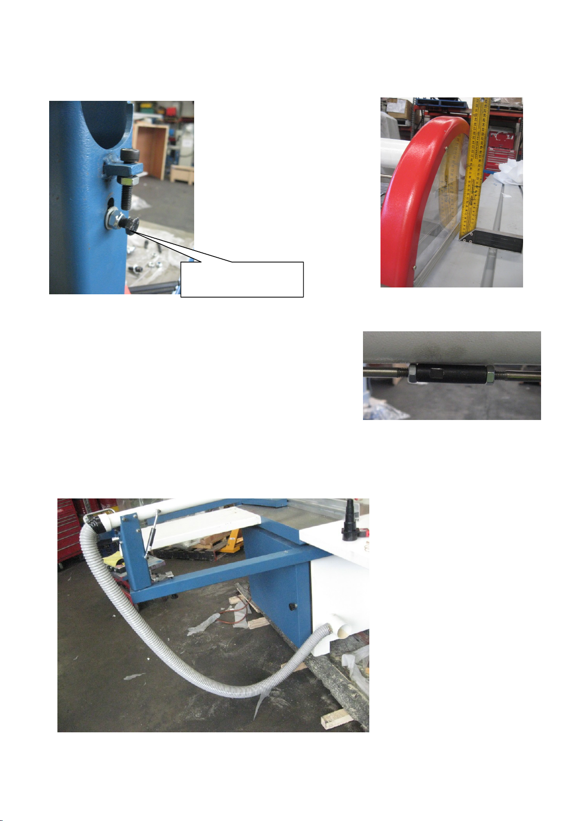
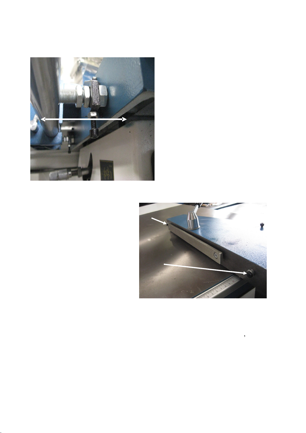
Fit sliding rear fence
Swivel blade guard out of the way.
Remove the first nut of each of the 3 studs coming off the rear fence sliding rod
Leaving 2 thin locknuts locked together on 2 of the studs and 1
x thicker nut on the other with one
washer. Wind this nut all the way towards rod.
Insert the 3 studs into the 3 holes.
Carefully with assistance and concentrating on
the front 2 studs
going into the cast mounting
brackets.
Fit a washer and nut on to eac
h and screw nut on
until stud can be seen just coming out of each nut
Pushing the studs down onto the adjustment bolts
in the slots, tighten up these 2 nuts
Carefully slide on the fence sliding casting
Note the position of lock lever. The pin may
have
to be pushed in to slide lock clamp over
shaft
Slide the casting up to the main table
Fit the fence extrusion onto the sliding casting,
lock in place and then slide the fence assembly
up approximately 100mm off the
aluminum
insert in the blade gap.
Me
asuring as shown by the 2 arrows
When fitting
sliding fence
casting to rod
Ensure lever is
in this position
as shown
This pin may
have to be
pushed down!
Rea
r fence sliding rod
Rear Fence
measurement tape
extrusion

10
The fence can now be adjusted parallel with this insert if needed by adjusting the 2 inner stud nuts of
the fence rod as needed. Ensure the rod is always pulled down on the adjustment screws and lock
the second lock
nuts tight when setting is achieved
The
aluminum
fence level and parallel can be adjusted if needed by loosening and turning the cams in
the sliding casting that the fence slips on.
Now carefully, sliding the fence
assembly out off the main table and onto the sheet metal outrigger
table, the level of the outrigger table can be adjusted as needed up or down so the roller of the sliding
fence casting transitions smoothly over the join.
The outrigger table may also ne
ed adjusting of its tilt as well to ensure the fence doesn t scrape.
With the fence now all the way out, its parallelism with the blade slot can be rechecked as well
While fitting a washer and nut onto the 3
rd
outer stud, the rod can be slightly pushed in
or out while
being locked in place to ensure fence is still parallel to blade slot.

11
Fit fence measure
Remo
ve the 3 x M6 socket heads cap screws from above the fence rod and fit the RHS measuring
assembly
(This will need setting later when blade
is put on machine)
Fit Push stick mount onto top of sliding casting
as shown
Slide fence out over
onto sheet
metal extension table and
adjust table as needed

12
Fit sliding table outrigger frame
Swing out outrigger pivot arm.
Remove rubber stopper of the
end of outrigger extension arm
and carefully in
sert arm
with
location bolt sticking up,
into
outrigger assembly
. When all the
way through refit rubber stopper
tightly.
Carefully unwrap the outrigger
table being sure to find an alloy
block and 2 x ratchet handles. Put
aside for later
Ensuring main sliding table is in a locked position, fit the sliding
carriage onto the location bolt of the outrigger extension arm at the
same time sliding the table hooks
in from the front end of the
sliding table.
Slide assemble to the middle of
the sliding table a
nd lock in
position.
Using a straight edge across the
sliding table over to the roller on
the outrigger table check and
adjust height as needed by
undoing the lock nuts on the
location pin and moving up or
down as needed. Ensure nuts are
all locked when
done.
Out
rigger
pivot arm
Outrigger extension arm
Adjust and relock nuts,
top and bottom as needed

13
Fit front fence
Sit aluminum riser block on outrigger as shown
Sit fence on its side as shown and align the 2 x locating pins front
and back and the middle lock down bolt as shown.
Tilt fence over the right way
locating the 3 in p
erspective
holes.
Screw in 1 ratchet handle to front pivot pin.
Holding alloy riser block up onto fence, swing fence to the rear of machine and fit large washer and
locking Knob onto middle stud. Swing fence back and fit other ratchet handle t
o outer locating pin.
Ensuring fence is pulled back against stop,
( slid away from blade and swung to be on 90 degrees)
lock it in place.
Fit one of the sliding stops to the extension block. Push all the way to the pin in the block and lock in
place.
Fence extension
block
Sliding stops

14
Fit a smaller magnifier line to it
( 3 x magnifying lines found in blade box)
Fit the other sliding stop to the main arm and
screw on a small magnifying line
Fit magnifying sight (large one) to fence
extension arm
Fit
thigh pushing bar
Remove plastic plug from end of tube
that has drilled hole in. Remove 2 x
nuts off screw in frame and refit as
shown with 2 x lock nuts locked
together and RHS can still
swing
freely
Refit plastic end cap
Pushing bar

15
Fit Right hand table extension guard as shown
Fit work
clamp
Slide onto
end of table
and lock in
place when
needed.
Fit blades
Extreme care must be taken due to sharp blade teeth.
Ensuring machine is not connected to power
Slide table assembly all the way back to gain access to blade area
Pull lower blade guard assemble open
NB blade nuts undo the direction the blade spins in use. Main blade Clockwise Scribe blade Anti-
Clockwise) (se
e pic)
Fitting scribe blade
( turns anti
-
clockwise in use)
With large double ended spanner and 10mm
allen
key supplied fit key in spindle hole and undo nut
anti
-
clockwise. Remove nut and support flange completely
Fit scribe blade then flange and nut, do u
p nut tightly using opposite forces against
allen key
Fit main blade
( turns clockwise in use )
With large double ended spanner
and 10mm
allen
key supplied fit
key in spindle hole and undo nut
clockwise. Remove nut and
support flange completely
Fit main
blade then flange
ensuring both are sitting correctly
on the 2 x locating pins then screw
on nut
do up nut tightly using
opposite forces against allen key.

16
Setting height of Riving
Knife
The riving knife height can now be
set (just under height o
f blade cut)
Put a bit of scrap wood behind
main blade and wind blade up level
with the top of it.
Undo riving knife lock bolt and
move riving knife as needed to be
just under level of wood
Lock bolt tight
Lift up lower blade guard and push
back close
d
Wind main blade all the way down
Setting measurement tapes on outrigger fence
Ensuring machine is not connected to power
Line outrigger table fence up with main blade (lock table in position)
Set rear
measurement
tape of fence
Slide
out extension
arm
and m
easure
with a
separate tape measure, 200cm
from
the saw
blade to
the
flip over stop
on the end of the
extension arm. Lock extension in place
The m
easurement tape in the
aluminum
extrusion
can now be set to 200
cm under the
magnifier line
by unscre
wing small knob
under the fence,
sliding
the
tape in
the
slot
as
needed and locking the knob again
(NB ends of
metal
tape
in the slot
may have
to be trimmed to suit)
F
inal adjustment can be done after taking
a
test cut and re
-
measuring at a later dat
e
Ensuring machine is not connected to power
Set front
measurement
tape of fence
Flip over a length stop
m
easure
with a separate tape measure, 100cm
from
the saw
blade to
the
flip
over stop
on the fence.
The m
easurement tape in the
aluminum
extrusion
c
an now be set to
100
cm under the magnifier line
by unscrewing small knob
under the fence,
sliding
the
tape in
the
slot
as needed and locking the knob
again
(NB ends of
metal
tape
in the slot
may have to be trimmed to suit)
Final adjustment can be done
after taking
a test cut and re
-measuring at a later date
Front
fence tape setting
knobs

17
Ensuring machine is not connected to power
Set measurement of tape on rear fence
Bring the fence 100mm away from blade measuring it with a tape measure as shown.
Loosen the tape adjustment screw
found under the RH end on the alloy extrusion the tape is set in
Slide the tape in the extrusion to show 100mm under the fence and then tighten the screw again.
Final
adjustment can be done after taking
a test cut and re
-measuring at a later date
# Setting of overhead guard
The blade guard MUST always be in place over the blades when machine is in use
Final adjustment of positioning of the guard may need to be done again as per directions explained
previously.
The height of the blade guard must a
lways be set
with the bottom of the guard down to
the thickness
of the material being cut.
This is adjusted by releasing the lock nut on the rear upright of the blade arm assembly and turning
the socket head cap
screw
as needed
UP (anti clockwise) to mov
e the guard closer to the table and DOWN (clockwise) to lift the blade
guard up higher
When set correctly ensure the screw is locked in place by locking the nut.
Always ensure the rear cover of the blade guard is
fitted correctly to suit the cut being u
sed
Clear straight one for 90 deg cuts
Blue
fiberglass
one for cuts to 45 degrees
Blade Guard height Setting Screw
(Shown with lock nut loose)

18
Putting power to machine and testing operation
# Swing the blade guard over the blade.
Wind blade fully up
Wind blade to be on the 90 degree stop.
# Ensurin
g the isolation switch on the RH side of the machine is in the off position ( 0 ), the
emergency stop on the front panel is depressed and the scouring saw switch in the OFF position,
Have a fully licensed Electrician put power to the machine.
# Turn the
isolation switch to ON ( 1 ) position and release the emergency stop button.
# Check correct rotational direction of them main blade by quickly pressing the MAIN SAW ON
Button and straight after that main saw OFF Button
The main blade should spin clo
ckwise.
If it does not, have licensed electrician reverse the phase direction of the power to the machine.
Retest as above and when all is correct, switch on the SCOURER BLADE,
This should go anticlockwise,
(NB the Scouring blade will not operate unless the main blade is switched on)
# The Blade Angle LED may be flashing. If so press and HOLD down the small red reset button
under the LED panel for 10 to 20 seconds.
LED will set itself to 00.00
NB: the resetting of the LED may have to be done if
the Emergency stop is pressed or there is a power
cut when the blade is not on 90 degree cut
Always wind blade to 90 deg before resetting to 00.00
Reset button to
Zero DRO
Main blade On/Off
Buttons
Scouring blade On/Of
f switch
Will only operate when main blade is
turned on.
Emergency Stop Button
Only
Do not use to turn blades off in general use
Blade Angle LED
Power on Li
ght

19
Blade guard
Please note the saw is supplied with 2 different rear covers for the blade guard.
A 45 degr
ee one that must be fitted when tilting the blade and one that is for straight cutting
Ensure the correct guard is used at all times.
Setting scouring blade.
The Scouring (or Scriber) blade will need to be set when used
Lef
t and right adjustment is done by the Right hand Screw
Up and Down adjustment is done by the Left hand Screw
Guard for tilted blade
Guard for 90 degree
cut
Adjusts Scouring blade
left and Right
Clockwise moves blade to
the Left!
Adjusts Scouring
blade Up and Down
Lock Nuts.
T
o be locked in
place when bla
de is
set

20
Changing main blade speeds
The main blade has two speeds
Low 3800 RPM
( Belts on Pulley blade side )
High
5600 RPM
(Belts on Pulley Motor Side)
To change speeds
wind the blade all the way
down and tilt it to 30 degrees
( This will give you easier access to change the
belt )
Disconnect the power from the machine and open the rear door to the machine b
ase
Loosen the belt tensioning nuts on the tension lever and carefully move both belts over to the set of
pulleys required
Below picture is shown set up on Low speed
Belt tensioning nut.
One on top of block
(not shown)
and one below block
This manual suits for next models
1
Table of contents
Other Hafco Woodmaster Power Tools manuals