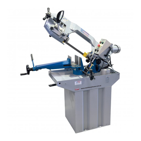
Hafco TS250SC User manual

20/7/08
(W460)
HAFCO
ST1265
SAWBENCH
PARTS MANUAL

INSTRUCTIONS
for 10” Table Saw w/Sliding Carriage
Model: TS250SC
FOR YOUR OWN SAFETY, READ ALL INSTRUCTIONS CAREFULLY BEFORE
USING THIS MACHINE

Table of Contents
1. Getting to Know Your Table Saw............................................................................................1
2. Please Read First......................................................................................................................2
3. Safety.........................................................................................................................................2
3.1 SpeciÞed conditions of use...................................................................................................2
3.2 General safety instructions................................................................................................2-3
3.3 Symbols used throughout these instructions........................................................................3
4. Special Product Features.........................................................................................................4
5. Operating Elements..............................................................................................................4-5
6. Initial Operation........................................................................................................................5
6.1 Installing side extension table...............................................................................................5
6.2 Installing the front rail............................................................................................................6
6.3 Installing the rear extension table..........................................................................................6
6.4 Installing the rip fence........................................................................................................6-7
6.5 Installing the riving knife........................................................................................................7
6.6 Installing the blade guard......................................................................................................7
6.7 Connection of dust collector..................................................................................................7
6.8 Installing the sliding carriage............................................................................................8-10
6.9 Mains connection................................................................................................................10
7. Operation................................................................................................................................10
7.1 Sawing................................................................................................................................11
7.2 Mitre cutting.........................................................................................................................11
7.3 Rip cutting with rip fenc........................................................................................................11
7.4 Sliding cut......................................................................................................................11-12
8. Care and Maintenance............................................................................................................12
8.1 Saw blade change...............................................................................................................12
8.2 Cleaning the saw.................................................................................................................13
8.3 Machine storage.................................................................................................................13
8.4 Maintenance.......................................................................................................................13
9. Tips and Tricks........................................................................................................................13
10. Repairs..................................................................................................................................13
11. Trouble Shooting..................................................................................................................13
12. Wiring diagrame...................................................................................................................15
13. Part lists and part breakdown.........................................................................................16-26
3.4 Safety devices...................................................................................................................3-4

1. Getting to know your saw
1. Box Stand
2. ON/OFF Switch with Emergency Stop
3. Saw Unit
4. Miter Gauge
5. Blade Guard
6. Rip Fence Extrusion
7. L Shape Fence Extrusion
8. Fence Rail
9. Handlewheel for Blade Tilting Set
10. Handwheel for Setting the Depth of Cut
11. Major Table
12. Right Extension Table
13. Extractable Stop Rail
14. Sliding Carriage
15. Swing Arm Assembly
16. Sliding Table Frame Assembly
17. Support Bracket
18. Rear Extension Table
19. Flip Stop
1
13 547612 8
17 15 21 31091116
19 14 18

2
3.1 Specified conditions of use
•This machine is intended to rip and crosscut
grown timber, faced boards, chip board and
wood-core plywood sheets, and similar wood-
derived materials.
•Do not cut round stock without suitable jigs or
Þxtures. The rotating saw blade could turn the
workpiece.
•When sawing thin stock layed on edge, a
suitable guide must be used for Þrm support.
Use of wobble saw blades is not permitted on
this machine.
Danger! Any other use is not as speciÞed.
2. Please Read First!
•4 Read these instructions before use. Pay
special attention to the safety instructions.
• Do not operate the saw if you notice transport
damage while unpacking! Notify your supplier
immediately.
• Dispose the packing in an environmentally
friendly manner. Take to a proper collecting
place.
• Keep these instructions for reference on any
issues you may be uncertain about.
• If you lend or sell this machine, be sure to
have the instructions go with it.
3. Safety
•Use not as speciÞed, alteration of the saw or
use of parts that are not approved by the
equipment manufacturer can cause
unforeseeable damage!
3.2 General safety instructions
•Observe the following safety instructions when
operating this table saw, to exclude the risk of
personal injury or material damage.
•Observe the special safety instructions in the
respective chapters. Keep all enclosed
documents for future reference.
•Observe the statuary accident insurance
institution regulations and regulations for the
prevention of accidents pertainning to the
operation of table saws, where applicable.
General Hazard!
•Keep your work area tidy – a messy work area
invites accidents.
•Be alert. Know what you are doing. Set out to
work with reason. Do not operate the saw
under the inßuence of drugs, alcohol or
medication.
•Consider environmental conditions.
•Keep work area well lighted.
•Prevent adverse body positions. Ensure Þrm
footing and keep your balance at all times. Use
suitable workpiece supports when cutting long
stock. Do not operate the saw near
inßammable liquids or gases.
•The table saw shall only be started and
operated by persons familiar with it, and who
are at any time aware of the dangers
associated with the operation of such tool.
•Persons under the age of 18 years shall
operate the saw only in the course of their
vocational training, under the supervision of
an instructor.
•Keep bystanders and particularly children out
of the danger zone. Do not permit other
persons to touch the saw or power cable while
it is running.
•Do not overload the saw – use it only within
the performance range it was designed.
Danger! Risk of electric shock!
•Do not expose the saw tool to rain.
•Do not operate the saw in damp or wet
environment.
•Prevent body contact with earthed objects
such as radiators, pipes, cooking stoves,
refrigerators when operating this saw.
•Do not use the power cable for purposes it is
not intended for.
Risk of personal injury and crushing by
moving parts!
•Do not operate this machine without installed
guards.
•Always keep sufÞcient distance to this saw.
Use suitable feeding aids, if necessary.
•Keep sufÞcient distance to motor and driven
components when operating this machine.
Insure it is disconnected from power supply
before servicing.

3
•Ensure that when switching on (e.g. after
servicing) no tools or loose parts are left on
or in the machine.
•Turn power off if the machine is not used.
Cutting hazard, even with the cutting tool at
standstill!
•Wear gloves when changing cutting tools.
Risk of kickback (workpiece is caught by the
saw blade and thrown against the operator)!
•Always work with a properly set riving knife.
•Do not jam workpieces.
•Cut thin or thin-walled workpieces only with
Þne-toothed saw blades. Always use sharp
saw blades. If in doubt, check workpiece for
inclusion of foreign matter (e.g. nails or
screws).
Drawing-in/trapping hazard!
•Ensure that no parts of the body or clothing
can get caught and drawn in by rotating
components (no neckties, no looseÞtting
clothes; contain long hair with hairnet).
Hazard generated by insufÞcient personal
protection gear!
•Wear hearing protection.
•Wear safety glasses.
•Wear dust mask if work generates dust.
•Wear suitable work clothes. When working
outdoors wearing of non-slip shoes is
recommended.
Risk of injury by inhaling wood dust!
Dust of certain timber species (e.g. beech, oak,
ash) can cause cancer when inhaled: use a
suitable dust collector.
Hazard generated by defects!
•Keep the machine and the accessories in
good repair and observe the maintenance
instructions.
•Check the machine for possible damage
before any use. Inspect all safety devices,
protection devices or slightly damaged parts
for proper functioning as speciÞed before
operatiing the machine. Check to see that all
moving parts work properly and do not jam. All
parts must be correctly installed and meet all
conditions necessary for the proper operation
of the machine.
•Damaged protection devices or parts must be
repaired or replaced by an qualiÞed specialist.
•Do not operate the machine if the switch can
not be switched ON or OFF.
•Keep handles free of oil and grease.
3.3 Symbols used throughout these
instructions
Danger!
Indicates risk of personal injury or severe
material damage
Risk of electric shock!
Risk of personal injury by electric shock
Drawing-in/trapping hazard!
Risk of personal injury by body parts or clothing
being drawn into the rotating saw blade
Caution! Risk of material damage
Note:Supplementary information
3.4 Safety devices
Blade guard
•The blade guard (a) (Figure 1) protects
against unintentional contact with the saw
blade and from chips ßying about.
•Always have blade guard installed during
operation.
Riving knife
•The riving knife (b) (Figure 1) prevents the
workpiece from being caught by the rising
teeth of the saw blade and being thrown
against the operator.
•Always have blade guard installed during
operation.
Figure 1

4
Push stick
•The push stick (P) (Figure 2) serves as an
extension of the hand and protects against
accidental contact with the saw blade.
•Use push stick if the distance from the rip
fence to the saw blade is more than 120 mm.
Be sure the push stick be always at hand.
Figure 2
4. Special Product Features
•Precisely adjustable bevel tilt from 0° through
45°
•Steplessly adjustable depth of cut 0 – 80mm
•All operating elements are located at the
machine’s front
•An undervoltage relay prevents the machine
from starting up when power is restored after
a power failure
•Standard mitre fence and rip fence
•Extractable stop rail and end stop
•Smooth sliding carriage with swing arm
support
•Easy assembly and adjustment
5. Operating Elements
ON/OFF switch with emergency stop
•To switch ON=depress upper green button (a)
(Figure 3)
•To switch OFF=push upper red button (b)
(Figure 3) or on switch cover.
Note: Upon power failure an undervoltage
relay is activated. This prevents the starting of
the machine when the power is restored. To
restart the saw after a power failure the green
switch button (a) needs to be actuated again.
Figure 3
Handwheel for setting the depth of cut
•The depth of cut can be adjusted by turning the
handwheel (c) (Figure 4)
Handwheel for blade tilt setting
•With the handwheel (d) (Figure 5) the saw
blade can be steplessly tilted to the right from
0° (vertical) through 45°.
Rip fence
•The rip fence slides on the saw table’s front
rail.
Figure 4
Figure 5

5
Miter gage
•The miter gage is used in making cross cuts in
the workpiece.
• Adjust the angle (Figure 7)
1, Loosen the knurled nut and the shorter lock
knob
2, Keep the longer lock knob by hand and turn
the locking handle counterclockwise.
3, Move the miter gage base to the desired
angle.
4, Securely tighten all the above loosened parts.
•Lock the miter gage on the work table
1, Loosen the knurled nut
2, Keep the locking handle by hand and turn the
longer lock knob clockwise
• Quick release
1, Push the quick release to move the hold
down clamp onto the workpiece quickly.
2, Turn the clamp knob and fasten the
workpiece
3, To prevent the use of the quick release, roll
the quick release stop around to the top of
the quick release.
Figure 7
Figure 6
Caution:
This table saw is shipped in two packages: the
master case and the sliding carriage carton.
Warning!
Do not lift the saw unit without help.
The saw unit weighs approximately 145 kgs.
Hold it close to your body. Keep your knees
bent and lift with your legs, not your back.
Ignoring these precautions can result in back
injury.
6.1 Installing side extension table
•Unpacking the master case. Take away the
case panels and take out the main unit of the
table saw from the pallet.
1, At the right side of major table, put 4-M8x30
hex head screws with 8 mm washer in holes,
so the screw heads extend outward 10mm.
Warning:
The table weights approximately 28 kgs.
Installing extension table needs another-man’s
help.
2, Take out the right extension table from the
cardboard box in the master case. Lift it
slightly and put in onto the 4 screws. Make
sure the four “U” shape slots be up on the
screws.
3, Center the extension table over the edges
and tap it. Check the surface alignment.
(Figure 8)
4, Tighten 4-screws with a 12mm wrench.
Figure 8
6. Initial Operation

B
6.2 Installing the front rail
Install the front rail needs following
hardwares:
4-M8x25 mm cross cylinder head screws
4-8 mm ßat washer
4-M8 mm hex self-lock nuts
1, Take out the front rail from the master case.
2, Align the front rail onto the front edge of table.
(Figure 9)
6
Figure 10
Figure 9
3, Put 4-M8x25 mm cross cylinder head
screws into the holes on the front rail.
(Figure 10)
4, Under table, loosely attach the ßat washers
and nuts onto screws.
5, Align the front rail parallel to the table then
tighten all screws.
6.3 Installing the Rear Extension Table
Install the rear rail needs following
hardware:
2-M8x25 mm Hex Head Bolt
2-M8 mm Nut
2-M8 mm Washer
2-M6x12 mm Grub Screw
3mm Allen Wrench
1, Take out the rear extension table from the
master case.
2, Align the rear extension table onto the rear
edge of major table.
3, Connect the rear extension table and the
major table by two M8x25 mm hex head bolts
and fasten the bolts by 8mm Wrench (A).
(Figure 11)
4, Use 3mm Allen Wrench to djust 2-M6x12 mm
grub screws (B), to adjust the ßatness of the
rear extension table and the major table.
Figure 11
AB
6.4 Installing the rip fence
1, Take out the rip fence part from the master
case.
2, Fit the handle (A) into the fence head (B) and
turn clockwise to lock it. (Figure 12)
3, Assemble the lens (C) to the fence head (B)
by a Pan Head Screw M4x10 mm.
Figure 12
A
C

7
6.5 Installing the riving knife
1, Take out the riving knife from the loose part
bag.
2, Loosen screw (a) of the riving knife bracket
3, Insert the riving knife (b) into the riving knife
bracket.
4. Adjust the distance between the saw blade’s
outer edge and the riving knife(b). It must be
3-8mm. (Figure 13)
Figure 13
6.6 Installing the blade guard
• Install blade guard (a) on riving knife(b).
4, Slide the rip fence back and forth. It should
move freely with about 2mm clearance below
the rip fence. If it dosen’t, loosen the screws
of the front rail, and adjust it up or down.
Retighten all screws again.
5, Push down on the rip fence handle to lock the
rip fence in place.
Figure 14
6.7 Connection of dust collector
Danger!
• Dust of certain timber species (e.g. oak and
ash) can cause cancer when inhaled.
• Always use a dust collector when working in
enclosed spaces (air speed at the saw’s dust
collection port ≥20 m/s).
Caution!
• Operation without a dust collector is only
possible:
- outdoors;
- for short-term operation (up to max. 30
minutes);
- with dust respirator.
• If no dust collector is used, saw dust and chips
may accumulate inside the machine housing
These remains have to be removed after 30
minutes at the latest.
1, Dust collection ports are located on the chip
case and blade guard.
2, Fit the small ejection tube on blade guard.
3, From the hole of table saw rear panel, pull out
the chip ejection tube.
4, Fit the chip ejection tube onto three-way tube.
5, Fit the chip ejection tube of blade guard on
three-way tube. (Figure 15)
6, Then Þt the main chip ejection tube to Dust
collector.
Figure 15
Danger!
By the revolving motion of the saw blade the
saw dust is blown from the chip ejection tube.
Watch where the jet of saw dust is aimed at.

8
Caution!
In order for the saw dust to be effectively led off
the chip ejection tube supplied has to be
installed even if no dust collector is hooked up.
The chip ejection tube shall not be blocked by
other objects.
6.8 Installing the sliding carriage
1, Unpack the sliding carriage carton. Take out
the sliding carriage slightly. Take care and
keep well the loose parts inside the foam.
Take away the foam in a certain place.
2, Place the sliding carriage onto the two
supports (A) on the left side of the saw unit,
with the square guide piece (B) inserting on
the T-Slot of the bottom of the sliding carriage.
(Figure 16)
Fasten the Knurled Screws (C) tightly.
(Figure 17)
Warning!
Do Not lift the sliding carriage without help.
The length is approx. 1.70 m, while it weighs
approx. 25 kgs. Seek for other man’s help to
avoid unforeseen injury.
Figure 16
B
A
Be sure the safety switch is placed in the
correct position (Hole A) of the sliding carriage.
(Figure 18 - 1) Otherwise the machine can not
be switched on.
C
Figure 17
Figure 18 - 1
Safety Switch
Hole A
3, Assemble the lock handle (A) to the sliding
carriage by by 1-M12 Nut. (Figure 19)
Assembly the sliding carriage handle by
inserting the square nut into the T-Slot of the
sliding carriage. Turn colockwise to Þx it.
(Fugure 20)
Figure 19
A
M12 Nut
Handle Square Nut
Figure 20
Limiting Screw
Support Plate
Sliding Carriage
Safety Switch
Be sure to position the limiting screw next to
the support plate. It will help to correctly position
the sliding carriage. (Figure 18 - 2)
Figure 18 - 2
The safety switch may ensure the machine
not to run in case of the sliding carriage moving
away and may prevent people from been injured
by the saw blade.

9
Check the surface alignment of the major
table and the sliding carriage. Adjust the gurb
screws on the support plate for micro
adjustment. (Surface Alignment - 1)
Grub Screw
Surface Alignment - 1
4, Take out the sliding table frame (A) and the
support bracket (B) from the master case.
Attach the support bracket to the sliding table
frame by 2-M8 mm carriage bolts and 2-M8
mm nuts with washers in the bottom, and Þx it
by two wing screws in the left side.
(Figure 21)
Do not move the M20 nuts and thrust bearings
in the other end of the support bracket.
Figure 21
A
B
wing screw
thrust bearing
5, Attach the sliding table frame to the sliding
carriage, with the square nut insertting into
the T-slot of the sliding carriage. (Figure 22 - 1)
Attach the support bracket to the swing
arm (A), put the thrust bearing onto the
support bracket and Þx it by M20 mm nuts.
6, Slide the sliding carriage onto the sliding table
from the left end. Slide it forward to the end,
Þx the sliding table tightly by two wing screws.
(Figure 22 - 2)
Figure 22 - 2
Nut
Square Nut
A
Figure 22 - 1
7, Take the extractable stop rail (A) from the
sliding carriage carton and put it onto the
sliding table frame, with the positon pin (B) in
the hole at the corner of the sliding table.
Set it verticle to the sliding carriage and Þx it
by fasten the wing screw (C) beneath.
Attach the ßip stop (D) to stop rail (A) and Þx it
by the wing screw. (Figure 23)
Check the surface alignment of the sliding
table and the sliding carriage. Make micro
adjustment by loosing the M16 mm nut, and
adjust 2-M6 mm bolts and 2-M6 hex. nuts.
(Surface Alignment - 2)
M16 Nut
M6 Bolt & Nut
Surface Alignment - 2
A
BCD
Figure 23
8, Place the clamping plate (A) on the sliding
carriage, and Þx it by knuled Screw (B).
(Figure 24)

7. Operation
Risk of injury!
• This machine may only be operated by one
person at a time. Other persons may stay only
at a distance from the saw for the purpose of
feeding or removing stock.
• Before starting workoring, check to see that
the followings are in proper working order:
- power cable and plug;
- ON/OFF switch;
- riving knife;
- blade guard;
- push stick.
• Use personal protection gear:
- dust respirator;
- hearing protection;
- safety goggles.
• Assume proper operating position:
- at the front of the saw;
- in front of the saw;
- to the left of the line of cut.
- If working with two persons the second person
should stand at a rear table extension.
• In case of the type of work requires, use the
followings:
- table extension if working with two persons or
if otherwise workpieces would fall off the saw
table;
- dust collector.
• Avoid typical operator mistakes:
- Do not attempt to stop the saw blade by
pushing the workpiece against its side. Risk
of kickback.
- Always hold the workpiece down on the table
and do not jam it. Risk of kickback.
Drawing-in/trapping hazard!
• Never cut stock to which ropes, cords, strings,
cables or wires are attached or which contain
such materials.
- Never cut several workpieces at the same
time – and also no bundles containing several
individual pieces.
• Risk of personal injury if individual pieces are
caught by the saw blade uncontrolled.
9, Place the Miter Gauge on the major table,
with the miter gauge rod on the T-slot of the
major table. (Figure 25)
A
B
Figure 24
Figure 25
6.9 Mains Connection
Danger! Electrical Hazard!
• Operate the machine in dry environment only.
• Operate the machine only on a power source
matching the following requirements:
- mains voltage and system frequency conform
to the voltage and frequency shown on the
saw’s name plate;
- outlets properly installed, earthed and tested,
• Position power supply cable so it does not
interfere with the work and is not damaged.
• Protect power supply cable from heat,
aggressive liquids and sharp edges.
• Do not pull on power supply cable to unplug.
10

11
7.3 Rip cuts with rip fence
1, Lock the rip fence in required position on the
saw table.
Danger!
Use push stick if distance between rip fence and
saw blade is less than 120 mm.
7.1 Sawing
• For cutting the workpiece is evenly fed
against the saw blade towards the rear of
the table:
1, Set the depth of cut. The blade guard must
rest with its front edge on the workpiece.
2, Set blade tilt and lock in position.
3, Mount rip fence, if required.
4, Start sawing.
5, Cut the workpiece in a single pass.
6, Switch machine off if no further cutting is to
be done immediately afterwards.
Figure 26
7.2 Mitre cuts
1, Fit the miter gauge to the T-slot of the major
table.
2, Loosen lock knob, set fence to the desired
angle with the indicator and tighten the lock
knob again.
3, Hold the workpiece Þrmly against mitre gauge.
4, Cut the workpiece by pushing the mitre gauge
forward.
Figure 27
3, Set the depth of cut. The blade guard should
be approx. 10 mm above the workpiece.
4, Set the saw blade tilt and lock in position.
5, Switch on the machine.
6, Place the workpiece against the extractable
stop rail and hold it Þrmly.
Figure 29
3, Set blade tilt and lock in position.
4, Switch on the machine.
5, Cut the workpiece in a single pass.
6, Switch the machine off if no further cutting is
to be done immediately afterwards.
Figure 28
7.4 Sliding Cut
• With the sliding carriage and the sliding table
frame, large workpieces of max.size 1200 mm
x 2400 mm can be well guided and easily be
cut in half.
1, Put on the extractable stop rail onto the
sliding table frame (see item 7 of 6.8), and
lock it tightly with wing screws.
2. If necessary, set it to a required angle and
lock in position in correspondence with the
scale in the sliding table. (Figure 29)
2, Reposition auxiliary fence extrusion if
necessary:
- Low edge (as shown) = for sawing thin stock,
and with a tilted saw blade
- High edge = for cutting thick stock (max. 65
mm)

12
8. Care and Maintenance
Danger!
Prior to all servicing:
- Switch the machine OFF
- Unplug the power cable
- Wait untill the machine come to a complete
stop
• Check that all safety devices are operational
again after each service.
• Replace defective parts, especially of safety
devices, only with genuine replacement
parts.
• Parts not tested and approved by the
equipment maker can cause unforeseen
damage.
• Repair and maintenance work other than
described in this section shall only be
carried out by qualiÞed specialists.
8.1 Saw blade change
Danger!
Risk of injury by the saw blade’s teeth. Wear
gloves when changing blades.
1, Remove the blade guard.
2, Lower the saw blade fully.
3, Loosen the screws on the cover plate, and
remove the cover plate slightly.
4, Raise the saw blade fully.
5, To block the saw blade, insert the lock bar into
the hole in the saw table and turn the saw
blade by hand until the lock bar engages in
the saw spindle hole. (Figure 30)
Figure 30
6, Loosen the saw blade spindle arbor nut with
spanner (L.H. thread!).
7, Take the outer blade collar and saw blade off
the saw spindle.
8, Clean clamping surfaces of the saw spindle
and the saw blade.
Danger!
Do not use cleaning agents (e.g. for removing
resin residue) that could corrode the light
metal components of the machine; the
stability of the machine might be adversely
affected.
9, Put on a fresh saw blade.
Danger!
Use only suitable saw blades – when using
unsuitable or damaged blades, parts could be
explosive like hurled from it by the centrifugal
force.
Do not use:
- saw blades with visible damage;
- cut-off wheel blades.
10, Slide the outer blade collar onto the saw
pindle.
11, Screw the arbor nut, with the low side facing
the blade, onto the saw spindle(L.H. thread!).
Danger!
- Do not extent the arbor nut wrench.
- Do not tighten arbor nut by tapping on the
wrench.
- Do not forget to remove the saw spindle lock
bar after tightening the arbor nut!
- Keep surfaces of saw table and saw base
clean.
12, Loosen screw (a) of the riving knife bracket.
13, Adjust the distance between the edge of the
saw blade edge and the riving knife (b).
It must be 3-8mm. (Figure 31)
14, Reinstall the cover plate and blade guard.
Figure 31
7, Push the sliding carriage forward to cut
workpieces in a single pass.
8. Switch the machine off if no further cutting is
to be done immediately afterwards.

13
8.2 Cleaning the saw
1, Lay machine on its side.
2, Remove chips and saw dust with the vacuum
cleaner or brush:
- from saw blade setting guide elements
- from travelling sizing table guide elements
- from motor vent slots
8.3 Machine storage
Danger!
Store the machine so that
- it can not be started by unauthorized
persons, and
- nobody can get hurt.
Caution!
Do not store the machine unprotected outdoors
or in damp environment.
8.4 Maintenance
• Before switching on
- Visual check if distance between the saw
blade and the riving knife is 3-8 mm.
- Visual check of power cable and power cable
plug for damage. If necessary, have the
damaged parts been replaced by a qualiÞed
electrician.
• Monthly (if used daily)
- remove the saw dust and chips with the
vacuum or brush. Apply light coat of oil to
guide elements;
- threaded rod and guide rods of the blade rise
and fall mechanism;
- swivel segments.
Danger!
Repairs to electric tools must be carried out by
qualiÞed electricians only!
• Electric tools in need of repair can be sent to
the service centre of your country.
• Refer to the spare parts list for the address.
• Please attach a description of the fault to the
electric tool.
Danger!
• Before carrying out any fault service or
maintenance work always:
- switch machine OFF
- unplug power cable
- wait for saw blade to come to standstill
• Check to see that all safety devices are
operational after each fault service.
Motor does not run
• Undervoltage relay tripped by power failure:
- switch on again
• No mains voltage:
- check cables, plug, outlet and mains fuse
• Motor broken
- replace motor
10. Repairs
11. Trouble Shooting
• Make trial cut with pieces of scrap before
cutting a workpiece to size.
• Always place a workpiece on the saw table
in such way that it can not tilt or rock (e.g.
always place a curved board on the table
with the convex side up).
• When working long stock, use suitable
supports, such as table rear or side
extensions (optional accessories).
• Chip ejection tube blocked particular,
remove resin residue with a suitable
cleaning and maintenance spray.
9. Tips and Tricks Loss of cutting performance
• Saw blade blunt (possibly tempering marks
on blade body):
- replace saw blade (see section 6.1)
Chip ejection tube blocked
• No dust collector hooked up or suction
capacity insufÞcient:
- connect dust collector or
- increase suction capacity (air speed ≥20m/sec
at chip ejection tube)
Stated top speed is not reached
• Motor supply voltage too low:
- use a shorter extension cable or extension
cable with larger lead cross section (≥1.5 mm2).
- Have power supply checked by a qualiÞed
electrician.

14
12. Wiring Diagrams
Wiring Diagram 230V
Wiring Diagram 400V

15
1
2
3
4
5
6
7
8
9
10
11
12
13
14
100
101
102
103
104
105
106
107
108
109
110
111
112
113
114
115
116
117
118
119
120
121
122
123
124
125
126
Major Table
Front rail
Cross cylinder head screw Mx25
Cover plate
Hex head screw Mx30
Flat washer 8mm
Hex nut M8
Flat washer 8mm
Side Extension Table
Rear Extension Table
Grub Screw
Hex head screw M8x25
Countersunk head screw M5x8
Scale
Spring
Set collar
Hex socket head cap screw M5x20
Ring circlips 25mm
Chip-case guide panel, rear
Countersunk ßat head screw M5x6
Rubber foam
Spring roll
Pan head screw M4x8
Tube
Guide shaft
“O” ring
Hex thin nut M16x1.5
Special screw, Stop
Setting tube
Cup-washer
Spacer
Gear rod
Self-lock nut M6
Hex head screw M6x16
Supporting plate
Flat washer
Steel ring
Flat washer M8
Self-lock nut M8
Mount base
Bush
131
132
133
134
135
136
137
138
139
140
141
142
143
144
145
146
147
148
149
150
151
152
153
154
155
156
157
158
159
161
163
164
165
166
167
168
169
Arc plate
Steel ring
Self-lock nut M6
Chip-case guide panel, front
Pan head screw M6x10
Flat washer 6mm
Square, stop
Ring
Handle, bevel
Countersunk head screw M6x35
Flat washer 6mm
Hex nut M6
Flat washer 6 mm
Bevel angle scale
Lock knob
Hex shape shaft
Thread tube
Thread mount
Nylon ring
Pan head screw M5x6
Clamp, plate
Stop, moving
Flat washer 5 mm
Pan head screw M5x10
Pan head screw M6x10
Flat washer 6mm
Square, stop
Self-lock nut M4
Bevel indicator
Carriage bolt
Set collar
Hex socket head cap screw
Rise-lower handle
Flat washer 6 mm
Pan head screw M5x6
Rise-lower indicator
Handle
13. Part Lists and Part Breakdown
No. Part Description

16
201
202
203
204
205
206
207
208
209
211
212
216
217
218
219
221
222
223
224
225
226
227
229
231
232
233
234
235
236
237
238
239
241
243
244
245
246
247
248
249
250
251
252
253
254
Countersunk head screw M6x10
Bracket, motor
Flat washer 6 mm
Left-hand hex head screw M8x10
Ring plate, locking
Motor pulley
Motor
Pan head screw M4x6
Pan head screw M4x10
Flat washer 5mm
Guard fold
Left-hand hex nut M10
Outer blade collar
Self-locking hex nut M10
Flat washer 10 mm
Pressure plate
Riving knife
Guide plate
Blade guard
Dust collecting tube
Steel ring
Flat washer 6 mm
Cylinder head screw M6x20
Hex head screw M6x10
Tube
Carriage screw M10x35
Hex head screw M6x10
Flat washer 6mm
Lever
Hex nut M6
Countersunk head screw M6x10
Inner blade collar
Circlip 32mm
Hex nut M6
Mount, riving knife
Torsion
Ball bearing 80301
Pan head screw M4x6
Chipcase
Wiring band
M5x15 Screw / Flat washer 5mm, Hex nut M5
Dust collector
Bearing mount
Spindle
Adjustment ring
255
256
257
258
259
260
261
262
263
301
302
303
304
305
306
307
308
309
310
311
312
313
314
315
316
317
318
319
321
322
323
324
325
326
327
328
329
330
331
332
333
334
335
336
Ball bearing 80103
Circlip 35 mm
Pulley, spindle
Belt
Quill tube
Ball bearing 80301
Pulley, drive
Flat washer 8mm
Hex nut M8
Rear gear panel
Hex nut M8
Rear panel
Flat washer 6mm
Pan head screw M6x20
Right panel
Suction exit
Flat washer 8 mm
Socket head cap screw M4x8
Hex nut M6
Bracket
Taping screw M4x12
Flat washer 8mm
Hex head screw M8x30
Cross pan head screw M4x8
Cross pan head screw M4x60
Check plate
On/off switch
Socket head cap screw M4x12
Mount plate, switch
Left panel
Flat washer 4mm
Hex nut M4
Front panel
Front gear panel
Bevel scale
Flat washer 6mm
Hex head screw M6x20
Stop pin
Spring
Stop cap
Screw
Bracket, Safety Switch
Nut
Safety Switch
No Part Description
No. Part Description

17
This manual suits for next models
1
Table of contents
Other Hafco Saw manuals

Hafco
Hafco VB-450 User manual

Hafco
Hafco EB-270DSA User manual

Hafco
Hafco BS-7S User manual

Hafco
Hafco W434 User manual

Hafco
Hafco EB-350DSA User manual

Hafco
Hafco BS-250 User manual

Hafco
Hafco BS-7DS User manual

Hafco
Hafco T4I BS-250 User manual

Hafco
Hafco EB-351DSA User manual

Hafco
Hafco BS-13LS User manual

Hafco
Hafco BP-480 User manual

Hafco
Hafco BP-430 User manual

Hafco
Hafco BS-7DS User manual

Hafco
Hafco MetalMaster CS-315C User manual

Hafco
Hafco MetalMaster EB-260V User manual

Hafco
Hafco EB-280DSV User manual

Hafco
Hafco BP-255 User manual

Hafco
Hafco BP-480 User manual

Hafco
Hafco BP-305 User manual

Hafco
Hafco VB-45 User manual