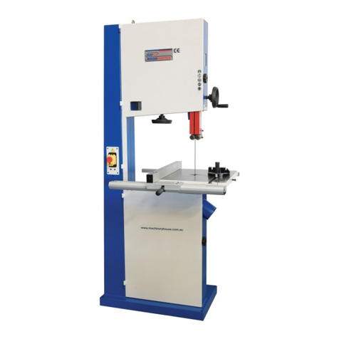
Hafco BP-430 User manual

INSTRUCTION MANUAL
BP-430
Wood Band Saw
415mm throat x 310mm Height Capacity
W433
04/11/2019
Instructions Manual for BP-430 (W433)
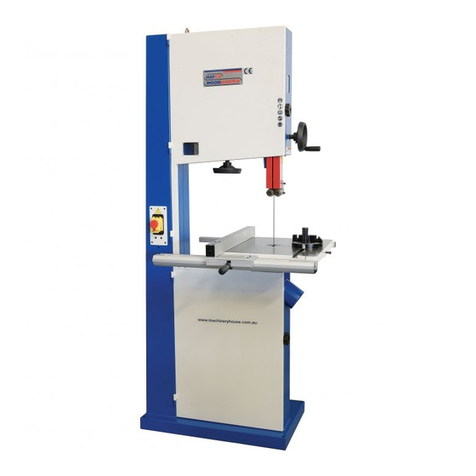
1

MODEL: BP-430 (W433)
OPERATION MANUAL AND PARTS LIST
WOOD BANDSAW
04/11/2019
Instructions Manual for BP-430 (W433)
2

TABLE OF CONTENT
1.
SPECIFICATIONSϭ
2.
WARNINGSϮ
3.
SAFETY INSTRUCTION FOR MACHINERYϯ
4.
IDENTIFICATIONϰ
FRONT SIDE OF BAND SAWϰ
REAR OF BAND SAWϱ
5.
OPERATING INSTRUCTIONϲ
LIFTING AND PLACINGϲ
ASSEMBLINGϲ
ADJUSTING 90 DEGREE TABLE STOPϲ
ASSEMBLING RIP FENCEϳ
CHANGING BLADESϳ
ADJUSTING THE TENSION OF BLADEϳ
ADJUSTING UPPER BLADE GUIDE ASSEMBLYϴ
DUST COLLECTIONϴ
SETTING THE CUTTING HEIGHTϴ
MITER GAUGE ADJUSTMENTϵ
SAFETY DEVICEϵ
6. PARTS LISTϭϭ
FEATURES:
The 17”(430mm) bandsaw is a well designed industrial machine that provide variety of wood work functions to meet
your higher need of a bandsaw. Followings are the basic functions you will find in this machine:
1. Quick Changed Saw Blade System gives you an easy way to replace saw blade to cut different quality wood
materials.
2. Adjustable Rip Fence can assist you to cut desired shapes.
3. Accurate Miter Gauge can let you create any curves you desire.
4. Effective Ball Bearing Guide System will let the band saw blade run smoother.
5. Humanized Dust Chutes collect extra wood-chips and give you a better working environment.
6.
Extended 12” Height Space provides you a bigger working space to cut wider and higher wood selections.
04/11/2019
Instructions Manual for BP-430 (W433)
3

ϭ
1.
SPECIFICATIONS
Horse
P
ower
2HP
Cutting
Height
12"(300mm)
Max. Cutting
W
idth
16-1/4"(410mm)
Max. Cutting (with Rip
F
ence)
14-5/8"(370mm)
Saw Blade
(L)
131.5"/3340mm
Saw Blade
(W)
1/8" to 1"
(Standard
1/2")
Saw Blade
Speed
(1,000/ 490 m/min.) (3,300/1,600SFPM)
Ta b l e
Size
17” x 17”(430x430mm)
Ta b l e
T
ilting
Left-10
o
/
Right-45
o
Wheel
Size
17"(430mm)
Table Height From
Ground
37.5"(950mm)
Dust Chute
Diameter
ȴ4" x 2
N.W./G.W.
121 / 146 KGS
Appearance
32” x 26” x 74”
Packing Size
(L x W x H)
30" x 20" x 80"
1
04/11/2019
Instructions Manual for BP-430 (W433)
4

2. WARNINGS
−
Misuse of this machine can cause se
r
−
For safety, machine must be set up, us
e
p
r
op
e
r
l
y
.
−
Read, understand and follow instruction
s
parts manual which was shipped with yo
When setting up machine:
−
Always avoid using machine is damp
o
a
r
ea
s
.
−
Always be sure machine is securely
a
n
−
Always keep machine guards in
p
l
a
c
e
.
−
Always put start switch in
"
OFF
"
posi
t
m
a
c
h
i
n
e
.
When using machine:
−
Never
operate
with machine guards
m
−
Always wear safety glasses with side
s
−
Never wear loose clothing or
j
e
w
e
l
r
y
.
−
Never overreach - you may slip and f
a
MAHINERY GENERA L S
A
1.
Always wear protective eye wear when
Eye wear shall beimpact
r
e
sis
t
a
n
t
, prot
e
with side shields. Not using
e
y
e
wear w
h
severe injury
f
r
o
m
breakage of eye
p
r
o
t
e
2.
Wear proper apparel. No loose clothing
o
get caught in moving parts.
Rubber
s
o
l
recommended
for best
f
oo
t
i
n
g
.
3.
Do not overreach. Failure to maintain
p
can cause you to fall into the machine
o
r
get caught - pulling you into
t
h
e
m
a
c
h
i
n
4.
Keep guards in place and in proper wo
operate
the machine with guards
r
e
m
o
5.
Avoid
dangerous
working
environmen
t
stationary machine tools in wet or damp
areas clean and well lit. Special
e
l
e
c
t
r
i
c
working on flammable materials.
6.
Avoid accidental starts by being sure t
h
"
OFF
"
before plugging in the
machine
.
7.
Never leave the machine running while
u
Machine shall be shut off whenever it is
n
8.
Disconnect electrical power before servici
n
accessories or general maintenance is don
e
electrical power to the machine must be di
is done.
Ϯ
r
ious injury.
e
d
a
nd
serviced
s
in the operator and
ur machine.
o
r
poo
r
l
y
lighted work
n
chored
to
t
h
e
fl
oo
r
.
t
ion
b
e
f
o
r
e
plugging in
m
issi
n
g
.
s
h
i
e
l
d
s.
.
a
ll into
t
h
e
m
a
c
h
i
n
e
.
−
Never leave machine r
u
−
Always shut off the ma
c
When servicing machine:
−
Always unplug machine
s
e
r
v
ici
n
g
.
−
Always follow instructi
o
when changing accesso
r
You - the stationary power t
o
Read and follow these
full benefits from your machi
n
among the best in design and
used improperly can be
rende
r
absolutely
m
a
nd
a
t
o
r
y
that th
o
properly trained in how to use
understand
the
O
p
e
r
a
t
o
r
s
an
d
affixed to the
m
a
c
h
i
n
e
. Failur
e
can cause
s
e
r
i
ou
s i
n
j
u
r
i
e
s
A
FETY WARNINGS
op
e
r
a
t
i
n
g
machinery.
e
ctive safety glasses
h
ich could result in
e
c
t
i
on
.
o
r
j
e
w
e
l
r
y
which can
e
d
footwear is
p
roper
w
o
r
k
i
n
g
position
r
cause your clothing to
n
e
.
rking order.
D
o
not
v
e
d
.
t
s.
Do not
u
s
e
l
o
c
a
t
i
on
s
. Keep work
c
s should be used when
h
e start
s
w
i
t
c
h
is
u
n
a
tt
e
nd
e
d
.
n
ot
i
n op
e
r
a
t
i
on.
n
g. Whenever changing
e
on the machine,
sconnected before work
9.
Maintain all machine too
l
maintenance
instructions
of accessories. No
attem
p
have makeshift repairs d
o
voids the warranty but
a
l
s
10.
Machinery must be
anch
o
11.
Secure work. Use clamps
practical. It is safer than
hands to
operate
the
m
a
c
12.
Never brush away chips
w
13.
Keep work area clean. Clu
t
14.
Remove adjusting keys a
n
machine
on
.
15.
Use the right tool. Don't
job it was not designed
f
o
16.
Use only recommended ac
c
manufacturer’s
instructi
o
17.
Keep hands in sight and
c
cutting surfaces.
18.
All visitors should be ke
p
area. Make workshop co
m
master switches, or by re
m
19.
Know the tool you are u
s
and potential hazard.
u
nning while
y
ou
are away from
i
t
.
c
hine when not in use.
from electrical power
w
h
il
e
o
ns in
operators
and parts
m
a
nu
a
l
r
y tools or
p
a
r
t
s
.
o
ol user - hold the key to
s
a
f
e
t
y.
simple rules for best results
a
nd
n
e. Use properly, this
machine is
safety.
H
o
w
e
v
e
r
, any machine
r
ed
i
n
e
ffici
e
n
t
and unsafe. It is
o
se who
u
s
e
our products be
t
h
e
m
correctly. Should read and
d
Parts Manual as well as all labels
e
in following of these warnings
l
s with care. Follow
a
ll
for lubricating and
t
h
e
changing
p
t
shall be made
t
o
modify or
o
ne to
t
h
e
machine. This not only
s
o
renders the machine
un
s
a
f
e
.
o
red
to the
fl
oo
r
.
or a vise to hold work,
w
h
e
n
using your hands and it
f
r
ee
s
both
c
h
i
n
e
.
w
hile the machine is
i
n
op
e
r
a
t
i
on.
t
tered area invite accidents.
n
d wrenches before
t
u
r
n
i
n
g
force a tool or
attachment
t
o
do a
o
r
.
c
essories and
f
o
ll
o
w
o
ns
pertaining
to
t
h
e
m
.
c
lear of all moving parts
a
nd
p
t at a safe distance from
t
h
e
work
m
pletely safe by
u
si
n
g
padlocks,
m
oving
s
t
a
r
t
e
r
k
e
y
s
.
s
ing – its application limitations,
2
04/11/2019
Instructions Manual for BP-430 (W433)
5

ϯ
GENERAL ELECTRICAL CAUTIONS
This saw should be grounded in accordance with the National
Electrical Code and local codes and ordinances. This work should
be done by a qualified electrician. The saw should be grounded to
protect the user from electrical shock.
Caution:
For circuits which are far away from the electrical
service box, the wire size must be increased in order to deliver
ample voltage to the motor. To minimize power losses and to
prevent motor overheating and burnout, the use of wire sizes
for branch circuits or electrical extension cords according to the
following table is recommended.
3. SAFETY INSTRUCTION FOR MACHINERY
1.
Always wear leather gloves when handling saw
b
l
a
d
e
. The
operator
shall not wear gloves when
op
e
r
a
t
i
n
g
the
m
a
c
h
i
n
e
.
2.
All doors shall be closed, all panels replaced,
a
nd
other
safety guards in place prior to the
m
a
c
h
i
n
e
being started
or
op
e
r
a
t
e
d
.
3.
Be sure that the blades are not contact with
t
h
e
workpiece
when the motor is started. The motor
s
h
a
ll
be started and
you should allow the saw to come up
t
o
full speed before
bringing the saw blade into
c
on
t
a
c
t
with the workpiece.
4.
Keep hands away from the blade area.
See Figure A.
5.
Remove any cut off piece carefully while keeping
y
ou
r
hands free of the blade
a
r
ea
.
6.
Saw must be stopped and electrical supply must be cut off
before any blade replacement or adjustment of blade
support mechanism is done, or before any attempt is made
to change the drive belts or before any periodic service or
maintenance is performed on the saw.
7.
Remove loose performed on the unnecessary workpieces
from area before staring machine.
8.
Bring adjustable saw guides and guards as close as possible
to the workpiece.
9.
Always wear protective eye wear when
op
e
r
a
t
i
n
g
,
servicing, or adjusting machinery. Eyewear shall
b
e
impact resistant, protective safety glasses with
si
d
e
shields. Not using eye wear which could result in
severe injury
f
r
o
m
breakage of eye
protection.
See
Figure B.
10.
Nonslip footwear and safety shoes are
r
e
c
o
mm
e
nd
e
d
.
See Figure C.
11.
Wear ear
protectors
(plugs or muffs) during
e
x
t
e
nd
e
d
periods of
operation.
See Figure
D.
12.
Wear mask to operate machine.
See Figure E.
13.
Do not smoke during operating machine.
See Figure F.
14.
The workpiece, or part being sawed, must be
s
e
c
u
r
e
l
y
clamped before the saw blade enters the
w
o
r
k
p
i
e
c
e
.
15.
Remove cut off pieces carefully, keeping hands away
from saw
b
l
a
d
e
.
16.
Saw must be stopped and electrical supply cut off
o
r
machine unplugged before reaching into cutting
a
r
ea
.
17.
Avoid contact with coolant, especially guarding
y
ou
r
e
y
e
s
.
3
04/11/2019
Instructions Manual for BP-430 (W433)
6

ϰ
4. IDENTIFICATION
Throughout this document, we make reference to various systems
and components on the saw. The two illustrations on these pages will
provide you with an overall frame of reference for the location and
position of the various components.
Where detailed illustrations for various subsystems will be helpful,
you will find these illustrations accompanying the specific teat for
each subsystem and its components.
FRONT SIDE OF BAND SAW
4
04/11/2019
Instructions Manual for BP-430 (W433)
7

ϱ
REAR OF BAND SAW
5
04/11/2019
Instructions Manual for BP-430 (W433)
8

5. OPERATING INSTRUCTION
LIFTING AND PLACING
On the day that the machine arrives, make sure that a
crane or forklift with sufficient capacity is available to
unload the machine from the vehicle.
Ensure access to the chosen site is clear and that doors
and ceilings are sufficiently high and wide enough to
receive the machine.
1. Move the crate to the chosen location, then
remove the crate from the base
2. Unbolt the bandsaw from the pallet
3. Use the eye bolt supplied with the machine to
attach a certified lifting sling or hook (Refer Fig. 1).
4. Slowly lift the machine off the pallet and
carefully place it into position.
5. Once machine is set in place it is
recommended to level the machine and bolt it in place.
ASSEMBLING
1. Attach the hand wheel (see Figure 2) to the
machine.
2. Slide the table slot to the saw blade and slowly
move to the center of the table. Adjust the table
until the saw blade is in the center of table insert.
3. Install table insert. Then, install table gap screw
assembly, secure with (1) M8 nut, (2) M8 flat
washer and tighten gap screw. (see Figure 3)
4. Make sure the table is in the center. Then, secure
table to trunnion. Please use (1) M8 flat washer
(2) M8 spring washer, and (3) M8x25 hex head
bolt to secure. (see Figure 4)
Eye Bolt
Figure 1
Handle Wheel
Figure 2
Figure 3
Figure 4
6
04/11/2019
Instructions Manual for BP-430 (W433)
9

ADJUSTING 90 DEGREE TABLE STOP
1. Unplug power cord. Loosen the lock knobs (see
Figure 5) and tilting table left until it rests against
table stop bolt M8. (A, Fig. 6)
2. Use a protector placed on the table and against the
blade (Fig. 7) to see if the table is 90 degree to the
table. If it is not 90 degree, you can use micro-
adjust knob. Please lock the lock knob.
ASSEMBLING RIP FENCE
1. Setting the fixed base to the cast iron table with
two M6x20 hex head bolts and two M6 spring
washers. (Fig. 8)
2. Setting the square tube to the table with two
M6x16 hex socket bolts.
3. Setting the fence to the fence body. Place the
fence assembly on the fixed base and slide the
fence on its guides until it is the required
distance from the blade.
4. Check the scale, make sure the distance
between the edge of the miter slot and both the
front and rear of the rip fence. Adjust so both
distances are equal.
5. Lock the fence by pushing the locking handle.
CHANGING BLADES
1. Unplug power cord.
2. Remove the table insert and table pin.
3. Open upper and lower wheel cover.
4. Loosen the upper and lower blade guide system
and bearing.
5. Loosen quick change saw blade system lever on
rear of bandsaw.(see Figure 9)
6. Remove the blade and guide new blade through
table slot. Place blade in upper and lower ball
bearing guides system.
7. Replace blade in the MIDDLE of the upper and
lower wheel. If the blade is not in the right
position, you must relax the fixed handle and
adjust the tracking control knob.(see Figure 9)
8. Replace the table insert and table pin.
9. Adjust the blade tension and blade tracking if
the blade width is different.
Square tube
Fixed Base
Figure 8
Quick Change
Saw Blade
System Lever
Tracking
Control Knob
Figure 9
Fence
Figure 5
Figure 6
Figure 7
7
04/11/2019
Instructions Manual for BP-430 (W433)
10

ADJUSTING THE TENSION OF BLADE
Blade tension is set by a spring loaded tension
mechanism on the upper wheel. Check the level of the
tension device before cutting. The tension for various
blade widths as indicated on the window of upper
wheel cover.
Turn the blade tension hand wheel (see Figure 10) and
see the saw tension instruction (see Figure 11)
indicated on the window of upper wheel cover.
ADJUSTING UPPER BLADE GUIDE
ASSEMBLY
1. Set the bearing of upper and lower blade guide
within approx. 0.5mm of the blade. Make sure the
bearing and the back of the blade approx. 0.5mm.
(see Figure 12 and Figure 13)
2. Do not set the bearing too close. The friction
generates heat, which may have an adverse effect
on the bearings and the saw blade.
DUST COLLECTION
The band saw is recommended to be connected to dust
collect. There are two 4”dust ports (see Figure 14) to
attach with 4”steel clamping.
SETTING THE CUTTING HEIGHT
The upper blade guide should always be set as close
practical against the work. To adjust, loosen the hand
wheel (see Figure 15) at the side of housing and see
the blade guide to the required height. Then, tighten
after setting.
Figure 10
Figure 11
Figure 13
Figure 12
Figure 14
Figure 15
8
04/11/2019
Instructions Manual for BP-430 (W433)
11

MITER GAUGE ADJUSTMENT
1. Place the miter gauge in the table slot.
2. Loosen the clamp screw on the miter gauge.
3. Adjust the desired angle of cutting on the miter
gauge.
4. Tighten the clamp screw. (see Figure 16)
SAFETY DEVICE
1. Limit switch (see Figure 17) inside the machine
body for cutting off the power while door
opening during operation.
2. Added door lock (see Figure 18) to link upper
and lower doors in between. To prevent the
door being suddenly opened during operation.
REMINDER
Once completing assembly, please test run the machine to ensure it is properly connected to power
and safety components are functioning correctly.
If you find an unusual problem during the test run, please stop the machine immediately. Disconnect
the machine from power and fix the problem before operating the machine again.
Figure 16
Figure 17
Figure 18
9
04/11/2019
Instructions Manual for BP-430 (W433)
12

6. STEPS FOR THE TABLE PARALEEL ADJUSTMENT
1. Insert table pin into table groove. (see
Figure 1)
2. Use a ruler gauge and put it on the table.
Adjust the position of the table pin
(adjust the depth of the pin) and adjust
the parallel of the table by using the
feller gauge. The tolerance for the table
parallel is within 0.4mm.
3. When adjusting the table, the table edge
can be higher than the middle position
about 0.4mm. Edge cannot lower than
the middle part of the table. (see Figure
2 & 3)
NOTE: To insert the table pin deeper,
the middle part of the table will be
lower.
4. Follow above steps to finish the table
parallel adjustment.
TROUBLE SHOOTING:
In case if the table pin stuck because you
push it to deep, use a round bar
φ5mm~φ8mm and soft hammer to knock the
table pin out from inside of the table. Please
be aware of your fingers!
Table Pin
Figure 1
Figure 2
Figure 3
10
04/11/2019
Instructions Manual for BP-430 (W433)
13

6.PARTS LIST
MODEL NO.W433
11
04/11/2019
Instructions Manual for BP-430 (W433)
14

12
04/11/2019
Instructions Manual for BP-430 (W433)
15

ITEM PART NO DESCRIPTION SIZE Q`TY
1 WF040808 FLAT WASHER M4xψ86
2 NH040700 NUT M4 4
3 SP040200 PAN HEAD SCREW M4x8 2
4 995101 RING M10 1
5 136161 MACHINE BODY 1
6 NF050800 NUT M5 2
7 IC135042 SWITCH CORD 1
8 WF061310 FLAT WASHER M6xψ13 2
9 IC135001 POWER CORD 3P+G 1
10 NH061000 NUT M6 1
11 135040 POINTER 1
12 135073 STEP SCREW 1
13 135012 UPPER SHAFT 1
14 PS053500 SPRING PIN ψ5x35 1
15 135017 UPPER WHEEL SHAFT HINGE 1
16 135066 UPPER WHEEL SHAFT 1
19 AB135116T UPPER WHEEL ψ17" 1
21 WF083030 FLAT WASHER M8xψ30 2
22 SR089400 HEX SOCKET BOLT M8x16 2
23 135075 SAW BLADE 132"/3352.8±4.2x1/2"x0.5mm 1
24 WS080000 SPRING WASHER M8 2
27 AB135119T LOWER WHEEL ψ17" 1
29 NH633801 NUT 1"-14 UNF 1
30 WS630000 SPRING WASHER 1" 1
31 IM135001 MOTOR CORD 1
32 135032 SPRING 1
33 PS031600 SPRING PIN ψ3x16 1
34 135042 LOCATE BLOCK 1
35 994301 BEARING 51201 1
36 170245 CE SWITCH KJD-11-11D(JD3) 1
13
04/11/2019
Instructions Manual for BP-430 (W433)
16

ITEM PART NO DESCRIPTION SIZE Q`TY
37 135002 HANDLE WHEEL 1
38 135003 ADJUSTING BOLT 1
39 SF050200 PAN HEAD BOLT W/FLANGE M5x10 10
40 WE050000 STAR WASHER M5 4
41 NH040700 NUT M4 2
42 NH050900 NUT M5 4
43 135070 SWITCH PLATE 1
44 SR089400 HEX SOCKET BOLT M8x16 2
45 WF083030 FLAT WASHER M8xψ30 2
46 135016 UPPER WHEEL SLIDING BRACKET 1
47 SR060500 HEX SOCKET BOLT M6x25 1
48 BR000044 RIVET ψ3.2x10 8
49 SR060200 HEX SOCKET BOLT M6x10 1
50 135004 LIMPID PIECE 2
51 SF040700 PAN HEAD BOLT W/FLANGE M4x35 2
52 136475 DOOR LATCH SWITCH(ASM) AZD-S11 1
53 WS050000 SPRING WASHER M5 2
54 WF051210 FLAT WASHER M5xψ12 2
55 136164 UPPER WHEEL COVER 1
56 SH060500 HEX HEAD BOLT M6x25 2
57 WF061310 FLAT WASHER M6xψ13 2
58 135051 BRUSH 2
59 SR060500 HEX SOCKET BOLT M6x25 1
60 135041 KNOB 2
61 NL061000 NYLON NUT M6 6
62 709416 STRAIN RELIEF M16 2
63 135011 HEIGHT POINTER 1
64 NH081300 NUT M8 1
65 SH081800 HEX HEAD BOLT M8x90 1
66 135022 KNOB SCREW M10x20 1
14
04/11/2019
Instructions Manual for BP-430 (W433)
17

ITEM PART NO DESCRIPTION SIZE Q`TY
67 135020 KNOB SCREW M10x53 1
68 135028 LOCATE HANDLE M10 1
69 135030 CAM 1
70 135038 LOCATE BLOCK 1
71 620021 KNOB 1
72 620020 LEVER ROD 1
73 NH121900 NUT M12 1
74 135036 SHAFT 1
75 SJ080400 HEX SOCKET BOTTOM HEAD SCREW M8x20 4
76 WS080000 SPRING WASHER M8 4
77 WS080000 SPRING WASHER M8 1
78 135013 COVER 1
79 SS080400 SET BOLT M8x20 4
80 NH081300 NUT M8 4
81 135005 LOWER WHEEL SHAFT 1
82 MH135001 MOTOR 1 HP 1
83 SR100500 HEX SOCKET BOLT M10x25 2
84 WS100000 SPRING WASHER M10 2
85 135064 MOTOR BRACKET 1
86 SJ080400 HEX SOCKET BOTTOM HEAD SCREW M8x20 4
87 135056 PLATE 1
88 SF050200 PAN HEAD BOLT W/FLANGE M5x10 2
89 135065 LOCATE BLOCK 1
90 KS050535 KEY 5x5x35 1
91 SH080402 HEX HEAD BOLT M8x20(L.H) 1
92 135008 MOTOR PULLEY 1
93 LA420000 V-BELT A42 1
94 SR060200 HEX SOCKET BOLT M6x10 1
95 136165 LOWER WHEEL COVER 1
96 SJ059400 HEX SOCKET BOTTOM HEAD SCREW M5x16 2
15
04/11/2019
Instructions Manual for BP-430 (W433)
18

ITEM PART NO DESCRIPTION SIZE Q`TY
97 WF083030 FLAT WASHER M8x30 1
98 SR100700 HEX SOCKET BOLT M10x35 2
99 NH101700 NUT M10 1
102 AB135021C TRUNNION SUPPORT BRACKET(ASM) 1
103 WS100000 SPRING WASHER M10 2
104 WF102325 FLAT WASHER M10xψ23 2
112 WF081820 FLAT WASHER M8xψ18 4
122 WS080000 SPRING WASHER M8 4
123 SH089400 HEX HEAD BOLT M8x16 4
125 AB198002 17" FENCE SET 1
126 135019 TABLE 17"x17" 1
127 135010 TABLE INSERT 1
128 100038 TABLE PIN 1
132 AB135095A LOWER BLADE GUIDE SUPPORT(ASM) 1
135 135035 RIGHT COVER 1
136 SR050200 HEX SOCKET BOLT M5x10 2
137 WF051210 FLAT WASHER M5xψ12 2
138 135034 PROTECT COVER(ASM) 1
140 135073 STEP SCREW 1
141 135054 FIBER WASHER ψ13x6x1.2 1
142 135037 SLIDING PLATE 1
145 AB135092 UPPER BLADE GUIDE SUPPORT(ASM) 1
152 SR060400 HEX SOCKET BOLT M6x20 2
158 135006 HANDLE WHEEL 1
159 SR060400 HEX SOCKET BOLT M6x20 1
162 SJ080400 HEX SOCKET BOTOM HEAD SCREW M8x20 4
163 WS080000 SPRING WASHER M8 4
164 AB135050 GUIDE BRACKET(ASM) 1
173 AB198101 MITER GAUGE ASS'Y 1
175 SS069300 SET SCREW M6x10 1
16
04/11/2019
Instructions Manual for BP-430 (W433)
19

ITEM PART NO DESCRIPTION SIZE Q`TY
176 135067 BUSHING 1
179 612112 BUSHING 1
180 WF081818 FLAT WASHER M8xψ18 4
17
04/11/2019
Instructions Manual for BP-430 (W433)
20
Table of contents
Other Hafco Saw manuals

Hafco
Hafco MetalMaster BS-5S User manual

Hafco
Hafco BP-480 User manual

Hafco
Hafco EB-351DSA User manual

Hafco
Hafco BS-13DS Guide

Hafco
Hafco VB-45 User manual

Hafco
Hafco TS250SC User manual

Hafco
Hafco BS-7DS User manual

Hafco
Hafco BS-460AS User manual

Hafco
Hafco BS-13LS User manual

Hafco
Hafco BS-250 User manual

Hafco
Hafco MetalMaster CS-315D User manual

Hafco
Hafco W434 User manual

Hafco
Hafco MetalMaster CS-350V User manual

Hafco
Hafco BP-255 User manual

Hafco
Hafco BP-305 User manual

Hafco
Hafco VB-450 User manual

Hafco
Hafco T4I BS-250 User manual

Hafco
Hafco MetalMaster EB-260V User manual

Hafco
Hafco EB-270DSA User manual

Hafco
Hafco BP-480 User manual