Hafco BP-255 User manual

WOOD BAND SAW
OPERATION MANUAL
Edition No :WBS-001
Date of Issue : 08/2017
Models
BP-255, BP-310, BP-360

2
OPERATION MANUAL
NOTE:
In order to see the type and model of the machine, please see the
specication plate. Usually found on the back of the machine. See
example (Fig.1)
Fig.1
WOOD BAND SAW
MACHINE
MODEL NO.
SERIAL NO.
DATE OF MANF.
NOTE:
This manual is only for your reference. Owing to the continuous improvement of the ma-
chine, changes may be made at any time without obligation or notice. Please ensure the local
voltage is the same as listed on the specication plate before operating this electric machine.
Distributed by
www.machineryhouse.co.nz
MACHINE DETAILS

3
OPERATION MANUAL
C O N T E N T S:
1. GENERAL MACHINE INFORMATION
1.1 Identication...................................................................... 4
1.2 Specications.................................................................... 5
2. IMPORTANT SAFETY INFORMATION
2.1 Safety Requirements........................................................ 6
2.2 Safety For Band Saws........................................................ 8
3. INSTALLATION
3.1 Site Consideration............................................................ 9
3.2 Electrical Installation..................................................... 10
3.3 Unpacking......................................................................... 11
3.4 Installation........................................................................ 12
3.5 Test Run.............................................................................. 14
4. ADJUSTMENTS
4.1 Tilting Table....................................................................... 15
4.2 Blade Tracking.................................................................. 15
4.3 Tensioning the Blade..................................................... 16
4.4 Adjusting Support Bearings....................................... 17
4.5 Blade Guide Adjustment............................................. 17
5. OPERATION
5.1 Basic Controls.................................................................. 18
5.2 Blade Information.......................................................... 19
5.3 Changing The Blade...................................................... 20
6. MAINTENANCE
6.1 Troubleshooting............................................................ 21
6.2 Wheel Alignment.......................................................... 22
Spare Parts............................................................................. 23
APPENDIX
Risk Assessment Sheets...................................................... 32

4
OPERATION MANUAL
Blade Tension Adjustment
Upper
Ball Bearing Guide
Blade Tracking Adjustment
Dust Port
Top Slide Adjustment
Mitre Gauge
Work Lamp
Switch
ON/OFF
Switch
Locking Fence
Stand
Motor
1.1 IDENTIFICATION
Fig. 1.1

5
OPERATION MANUAL
MODEL BP-255 BP-310 BP-360
Throat Capacity (mm) 245 305 340
Wheel Diameter (Ø) (mm) 255 310 360
Height Capacity (mm) 152 165 225
Table Size (mm) 360 x 320 480 x 390 545 x 515
Table Tilt 0 - 45° 0 - 45° 0 - 45°
Frame Type Steel Steel Steel
Blade Guide Type Ball Bearing Ball Bearing Ball Bearing
Motor Power (kW / hp) 0.37 / 0.5 0.75 / 1 1.1 / 1.5
Cutting Speeds (m/min) 400 / 800 370 / 800 370 / 800
Voltage / Amperage (V / amp) 240 / 10 240 / 10 240 / 10
Blade Order Code (Suits) W950A, W950B, W950F W420A, W420B, W420F W955A,W955B, W955F
Blade Size (L x W ) (mm) 1826 x 3-12.5 2240 x 3-20mm 2560 x 3-25mm
Floor Space (W x D x H) (mm) 750 x 650 x 1430 830 x 700 x 1590 920 x 800 x 1710
Shipping Dimensions (L x W x H)
(mm) 1020 x 450 x 380 1230 x 530 x 435 1350 x 575 x 440
Nett Weight (kg) 42 65 82
1.2 SPECIFICATIONS
NOTE:
The specications in this manual were current at time of publication, but because of our policy
of continuous improvement, HAFCO reserves the right to change specications at any time and
without prior notice, without incurring obligations.

6
OPERATION MANUAL
2. IMPORTANT SAFETY INFORMATION
2.1 SAFETY REQUIREMENTS
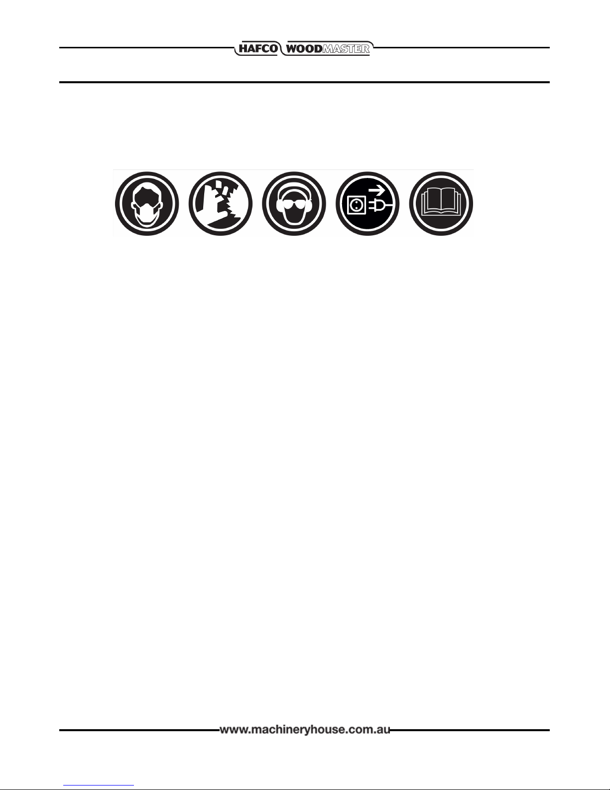
OWNER’S MANUAL. Read and understand
this owner’s manual BEFORE using machine.
TRAINED OPERATORS ONLY. Untrained
operators have a higher risk of being hurt
or killed. Only allow trained and supervised
people to use this machine. When machine
is not being used, disconnect the power, by
removing the power plug to disable the ma-
chine and prevent unauthorized use, espe-
cially when around children.
DANGEROUS ENVIRONMENTS. Do not use
machinery in areas that are wet, cluttered,
or have poor lighting. Operating machinery
in these areas greatly increases the risk of
accidents and injury.
MENTAL ALERTNESS REQUIRED. Full
mental alertness is required for the safe
operation of machinery. Never operate under
the inuence of drugs or alcohol, when tired,
or when distracted.
WEARING PROPER APPAREL. Do not wear
clothing, apparel or jewelry that can become
entangled in moving parts. Always tie back
or cover long hair. Wear non-slip footwear to
avoid accidental slips, which could cause loss
of workpiece control.
HAZARDOUS DUST. Dust created while
using the machinery may cause cancer, birth
defects, or long-term respiratory damage.
Be aware of dust hazards associated with
each workpiece material, and always wear an
approved respirator to reduce your risk.
HEARING PROTECTION. Always wear
hearing protection when operating or near
loud machinery. Extended exposure to this
noise can cause permanent hearing loss.
ELECTRICAL EQUIPMENT INJURY RISKS.
You can be shocked, burned, or killed by
touching live electrical components or im-
properly grounded machinery. To reduce this
risk, only allow qualied electrical personnel
to do electrical installation or repair work,
and always disconnect power before access-
ing or exposing electrical equipment.
DISCONNECT POWER FIRST. Always
disconnect the machine from power sup-
ply BEFORE making adjustments, changing
tooling, or servicing machine. This prevents
an injury risk from unintended startup or
contact with live electrical components.
EYE PROTECTION. Always wear approved
safety glasses or a face shield when operat-
ing or observing machinery to reduce the
risk of eye injury or blindness from ying
particles. Everyday eyeglasses are NOT
approved safety glasses.
REMOVE ADJUSTING TOOLS. Tools left on
the machinery can become dangerous
projectiles upon startup. Never leave keys,
wrenches, or any other tools on machine.
Always verify removal before starting!
USE CORRECT TOOL FOR THE JOB. Only use
this tool for its intended purpose—do not
force it or an attachment to do a job for
which it was not designed. Never make any
unapproved modications— modifying the
tool or using it dierently than intended may
result in malfunction or mechanical failure
that can lead to personal injury or death!
NEVER STAND ON MACHINE. Serious injury
may occur if machine is tipped or if the
cutting tool is unintentionally contacted.

7
OPERATION MANUAL
2.1 SAFETY PRECAUTIONS CONT.
AWKWARD POSITIONS. Keep proper
footing and balance at all times when
operating machine. Do not overreach! Avoid
awkward hand positions that make the work-
piece control dicult or increase the risk of
accidental injury.
CHILDREN & BYSTANDERS. Keep children
and bystanders at a safe distance from the
work area. Stop using machine if they
become a distraction.
GUARDS & COVERS. Guards and covers
reduce accidental contact with moving parts
or ying debris. Make sure they are properly
installed, undamaged, and working correctly.
FORCING MACHINERY. Do not force the
machine. It will do the job safer and better at
the rate for which it was designed.
MAINTAIN POWER CORDS. When dis-
conecting the cord-connected machines
from power, grab and pull the plug—NOT
the cord. Pulling the cord may damage the
wires inside. Do not handle the cord or plug
with wet hands. Avoid cord damage by keep-
ing it away from heated surfaces, high trac
areas, harsh chemicals, and wet or damp
locations.
STABLE MACHINE. Unexpected movement
during operation greatly increases risk of
injury or loss of control. Before starting, verify
machine is stable and mobile base (if used) is
locked.
USE RECOMMENDED ACCESSORIES.
Consult this owner’s manual or the manufac-
turer for recommended accessories. Using
improper accessories will increase the risk of
serious injury.
UNATTENDED OPERATION. To reduce the
risk of accidental injury, turn machine OFF
and ensure all moving parts completely stop
before walking away. Never leave machine
running while unattended.
MAINTAIN WITH CARE. Follow all mainte-
nance instructions and lubrication schedules
to keep machine in good working condition.
A machine that is improperly maintained
could malfunction, leading to serious per-
sonal injury or death.
CHECK DAMAGED PARTS. Regularly inspect
machine for any condition that may aect
safe operation. Immediately repair or replace
damaged or mis-adjusted parts before
operating the machine.

8
OPERATION MANUAL
2.2 SAFETY FOR BAND SAWS
BLADE CONDITION. Do not operate with
dull, cracked or badly worn blade. Dull blades
require more eort to perform the cut and
increase the risk of kickback. Inspect blades for
cracks and missing teeth before each use.
HAND PLACEMENT. Never position ngers or
hands in line with the blade. If the workpiece
or your hands slip, serious personal injury
could occur.
WORKPIECE MATERIAL. This machine is
intended for cutting natural and man-made
wood products, and laminate covered wood
products. This machine is NOT designed to cut
metal, glass, stone, tile, etc.
BLADE REPLACEMENT. To avoid mishaps that
could result in operator injury, make sure the
blade teeth face down toward the table and
the blade is properly tensioned and tracked
before operating.
BLADE SPEED. Moving the workpiece against
a blade that is not at full speed could cause
kick-back. Always allow the blade to come to
full speed before starting the cut.
GUARDS. The blade guard protects the oper-
ator from the moving band saw blade. ONLY
operate this band-saw with the blade guard
installed.
CUTTING TECHNIQUES. Plan your operation
so the blade always cuts to the outside of the
workpiece. DO NOT back the workpiece away
from the blade while the band saw is running,
which could cause kickback and personal
injuries. If you need to back the workpiece out,
turn the band saw OFF and wait for the blade
to come to a complete stop. DO NOT twist or
put excessive stress on the blade that could
damage it.
LEAVING WORK AREA. Never leave a machine
running unattended. Allow the band saw to
come to a complete stop and remove the plug
from the power point to disable the machine
before you leave it unattended.
FEED RATE. To avoid the risk of the workpiece
slipping and causing operator injury, always
feed stock evenly and smoothly. DO NOT force
or twist the blade while cutting, especially
when sawing small curves.
SMALL WORKPIECE HANDLING. Always sup-
port/feed the workpiece with push sticks, jig,
vise, or some type of clamping xture. If your
hands slip during a cut while holding small
workpieces with your ngers, amputation or
laceration injuries could occur.
BLADE CONTROL. To avoid serious personal
injury, DO NOT attempt to stop or slow the
blade with your hand or the workpiece. Allow
the blade to stop on its own.

9
OPERATION MANUAL
3.1 SITE CONSIDERATIONS
3. INSTALLATION
Weight Load
Check the Machine Specication plate mounted on the rear of the machine for the weight
of the machine. Make sure that the surface, the machine is placed on, will bear the weight
of the machine and any additional equipment that may be installed. This should include the
heaviest workpiece that could be used, when assessing the weight of the machine
Space Allocation
Consider the largest size of workpiece that will be processed through the machine and provide
enough space around the machine to adequately handle the largest workpiece or any acces-
sory that may be used. With permanent installations, leave enough space around the machine
to open or remove doors/covers as required by the maintenance and for service. See footprint
below (Fig.3.1)
Model A B
BP-255 750 650
BP-310 830 700
BP-360 920 800
Fig. 3.1
Environment
The physical environment where the machine is operated is important for safe operation and
longevity of the machine components. For best results, operate this machine in a dry environ-
ment that is free from excessive moisture, hazardous chemicals, airborne abrasives, or extreme
conditions. Extreme conditions for this type of machinery are generally those that are outside a
temperature range of 5°– 40°C. The environment should not be subject to vibration, shocks,
or bumps.

10
OPERATION MANUAL
Place this machine near an existing power source. Make sure all power cords are protected
from trac, material handling, moisture, chemicals, or other hazards. Make sure there is access
to a means of disconnecting the power source. The electrical circuit must meet the require-
ments for 240V. To minimize the risk of electrocution, re, or equipment damage, installation
work and electrical wiring MUST be done by an electrician or qualied service personnel.
Note ! The use of an extension cord is not recommended as it may decrease the life of electrical
components on your machine. NOTE: Hafco/Woodmaster advise that extension leads should
not be used permanently, but recommend that the plug be placed directly in to a wall socket.
3.2 ELECTRICAL INSTALLATION
Electrical Requirements
Nominal Voltage.......................................... 240V
Cycle................................................................ 50 Hz
Phase............................................... Single-Phase
Power Supply Circuit........................... 10 Amps
Full Load Current................................. 3.3 Amps
(Full load current rating is also on the specication plate on the motor.)
Full-Load Current Rating
The full-load current rating is the amperage a machine draws at when running at 100% of the
output power. Where machines have more than one motor, the full load current is the amper-
age drawn by the largest motor or a total of all the motors and electrical devices that might
operate at one time during normal operations.
Full-Load Current Rating at 240V...... 2.6 - 3.6 Amps
It should be noted that the full-load current is not the maximum amount of amps that the ma-
chine will draw. If the machine is overloaded, it will draw additional amps beyond the full-load
rating and if the machine is overloaded for a long period of time, damage, overheating, or re
may be caused to the motor and circuitry.
This is especially true if connected to an undersized circuit or a long extension lead. To reduce
the risk of these hazards, avoid overloading the machine during operation and make sure it is
connected to a power supply circuit that meets the requirements.

11
OPERATION MANUAL
1. Band saw 1pc
2. Guide rail 1pc
3. Table with insert 1pc
4. Rip fence 1pc
5. Short brace 2pcs
6. Leg 4pcs
7. Long brace 2pcs
8. Mitre gauge 1pc
9. Accessory tools assembly 1pc
10. Knob 4pcs
11. Hook with hex nut 1pc
12. Push stick 1pc
13. Hardware bag (not shown)
M6X10 socket head bolts 8pcs
M6X10 hex bolts 4pcs
6mm at washers 12pcs
M6X12 carriage bolts 8pcs
6mm at washers 8pcs
M6 hex nut 8pcs
M4X10 socket head bolts 2pcs
Read and understand all the assembly instructions before attempting assembly. Failure to
comply may cause serious injury. Remove all contents from shipping carton. Do not discard
carton or packing material until the band saw is assembled and running satisfactorily. Compare
the contents of carton against list of parts below. The number identication in the list corre-
sponds to items shown in Figures 3.2. This is your key for identifying the parts used throughout
the Assembly section for easy reference. Remove the protective coating that is applied to the
table with a household grease and spot remover.
1
2
3
4
5 6
7
8
910 11
12
3.3 UNPACKING
Fig. 3.2

12
OPERATION MANUAL
1. Stand Assembly
rPut down the machine on a timber (Fig. 3.3)
rAttach the legs to band saw by using M6X10
socket head bolts and 6mm at washers
rFix short braces and long braces to legs by using
M6x12 bolts, 6mm at washers and M6 hex nut.
Do not tighten the nut at this time.
rStand the band saw on a level ground, then
tighten all bolts and nuts. (Fig. 3.4)
3.4 INSTALLATION
2. Assembling Table
After attaching the stand, mount the table
on the band saw, using the M6X10 hex head
bolts and 6mm at washers.
Make sure the saw blade is in the centre of
table insert slot. (Fig. 3.5)
Fig. 3.3
Fig. 3.4
M6X10 socket head bolts
and 6mm at washers
M6X12 carriage blots, 6mm
at washers and M6 hex nut
Tighten nuts
3. Installing the Guide Rail.
Secure the guide rail with the four knobs to
the table. (Fig. 3.6)
Fig. 3.5 Fig. 3.6
M6X10 hex head
bolts and 6mm
at washers Guide rail
locking knobs

13
OPERATION MANUAL
4. Installing The Accessory Tools:
Attach the tool set to the back of the frame by using
M4X10 socket heat bolts. (Fig.3.7)
Secure the hook with hex nut to the end of the frame.
5. Installing The Rip Fence:
Place the rip fence onto the table, and secure it to the
guide rail.
Place the push stick onto the hook on the back of the
machine. (Fig.3.8)
NOTE: Get into the habit of always replacing the push
stick on the hook after use
Fence
Push Stick
Fig. 3.7
Fig. 3.8
Tool Set

14
OPERATION MANUAL
3.5 TEST RUN
Once the assembly is complete, test run your machine to make sure it runs properly. If, during
the test run, you cannot easily locate the source of an unusual noise or vibration, stop the
machine immediately, then review the Troubleshooting section on Page 21
If you still cannot remedy a problem, contact your distributor. The test procedure is as follows.
1. Make sure you have read the safety instructions at the beginning of the manual and that
the machine is set up properly, including Blade Tracking on Page 15
2. Make sure all tools and objects used during setup have been cleared away from the machine.
3. Connect the machine to the power source.
4. Turn the machine ON.
5. Listen and watch for abnormal noises or actions. The machine should run smoothly with little
or no vibration or rubbing noises. — Strange or unusual noises must be investigated and
corrected before operating the machine further. Always disconnect the machine from power
when investigating or correcting potential problems.
6. Turn the machine OFF
TABLE STOP CALIBRATION
After tilting the table the adjustable positive stop allows the
table to be reset 90˚ to the blade.
To set the positive stop:
1. DISCONNECT BAND SAW FROM POWER!
2. For the BP-255, adjust the blade tension see Page 16
(For BP-310, BP-360 adjust until the mark on the blade
tension scale matches the size of the installed blade.)
3. Loosen the hex nut that locks the positive stop bolt in
place and loosen the table tilt hand knobs.
4. Raise the guide post and place a machinist’s square on
the table next to the side of the blade, as illustrated in
Fig. 3.9. Adjust the table square with the blade, then
secure with the table tilt knobs.
5. Adjust the positive stop bolt to the table. (Fig. 3.10)
6. Secure the positive stop bolt by tightening the hex nut
against the trunnion bracket.
7. Check the adjustment for accuracy once you have
tightened the hex nut.
Blade
Positive Stop
Bolt
Fig. 3.9
Fig. 3.10
Table

15
OPERATION MANUAL
4. ADJUSTMENTS
WARNING: Always be sure that the machine is
switched o and unplugged before any
adjustment is commenced.
4.1 TILTING TABLE
Loosen the locking handle and adjust the table to
the desired angle.
Use the angle indicator scale to nd the desired
angle. The scale is only used as a guide. For very
accurate angle use a protractor against the blade.
Re-tighten the locking handle to secure the table.
Locking Handle
4.2 BLADE TRACKING
If the saw blade does not run in the center of the rubber tyre, the tracking needs to be correct-
ed by adjusting the tilt of the upper band saw wheel. To adjust the tracking open the upper
and lower covers.
Loosen the tracking lock lever,(Fig. 4.3) manually rotate the upper wheel, taking care no to
touch the blade.
Turn adjusting knob clockwise or anticlockwise until the saw blade tracks centered on the rub-
ber tyre. After adjusting, re-tighten the tracking lock lever and close the cover.
Fig. 4.1
Fig. 4.2 Fig. 4.3
Locking
Lever
Adjusting
Knob

16
OPERATION MANUAL
4.3 TENSIONING THE BLADE.
A properly tensioned blade is essential for making accurate cuts
and is necessary before making other band saw adjustments.
1. Raise the upper blade guide assembly as high as it will go,
and adjust the upper and lower guide blocks approximately
0.5mm away from the blade. (Fig.4.4 &Fig.4.5)
2. Adjust the blade tension knob. Turning the setting knob
clockwise will increase the blade tension and tuning the
setting knob counter-clockwise reduces the blade tension.
(Fig.4.6)
NOTE: This procedure will not work if the guide blocks have any
contact with the blade.
3. Check the tension by pushing with a nger against the side
blade, halfway between table and upper guide, (the blade
should ex not more than 2mm) (Fig.4.7)
4. Turn the band saw ON.
5. Very slowly release the tension one quarter of a turn at a time.
When you see the band saw blade start to utter, stop
decreasing the tension.
6. Now, slowly increase the tension until the blade stops
uttering, then tighten the tension another quarter of a turn.
WARNING: Too much tension can cause the band saw blade to
break. Too little tension can cause the driven band saw wheel to
slip and the saw blade to stop.
Fig. 4.4
Fig. 4.5
Fig. 4.7
BLADE TENSION INDICATOR BP310 & BP360
On the BP-310 and BP-360 the tension should be checked by viewing the blade tension indica-
tor. The scale indicates the correct adjustment of the blade in relation to the width of the band
saw blade. (Fig. 4.8)
Fig. 4.8
Fig. 4.6

17
OPERATION MANUAL
4.4 ADJUSTING SUPPORT BEARINGS
The support bearings are positioned behind the blade
for support during cutting operations. Proper adjust-
ment of the support bearings is an important part of
making accurate cuts. The procedure is as follows.
1. Make sure that the blade is tracking properly and
that it is correctly tensioned.
2. DISCONNECT BAND SAW FROM POWER!
3. Familiarize yourself with the support bearing
controls shown in Fig. 4.9
A. Locks the bearing support roller in place after it
has been moved back or forward.
B. Locks the complete Blade Guide assembly. When
unlocked the whole assembly can be mover
forward or back when out of adjustment.
4. Loosen the thumbscrew on the support bearing
adjustment shaft. (A in Fig.4.9)
5 Adjust the support bearing 0.5mm away from the
back of the blade, as illustrated in Fig. 4.10
6. Repeat Steps 4–6 for the lower support bearings.
4.5 BLADE GUIDE ADJUSTMENTS
The blade guides consist of an upper and lower
set of ball bearings that provide side-to-side support
to help keep the blade straight while cutting.
The blade guides are designed to be adjusted side-to-
side.
1. Make sure that the blade is tracking properly
and that it is correctly tensioned.
2. DISCONNECT BAND SAW FROM POWER!
3. Familiarize yourself with the blade guide controls
shown in Fig. 4.8.
C. The Socket head cap screws lock the side rollers
in place after they have been moved towards or
away from the side of the blade.
4. Undo the socket head cap screw of the blade
guide bearings.
5. Using a feeler gauge laterally position the bearings
0.1mm away from the blade. (C in Fig. 4.8)
6. Tighten the cap screw to lock the blade guide
bearings in position.
Repeat Step 4-6 for the lower guides.
B
A
C
Lower Guide
A
C
B
Upper Guide
Fig. 4.9
Fig. 4.10

18
OPERATION MANUAL
5. OPERATION
5.1 Basic Controls
Use the descriptions below to become familiar with
the basic controls of your machine.
Blade Tension Knob: Adjusts the tension on the
blade. (Fig. 5.1)
Blade Tracking Adjustment Knob: Adjusts the
blade tracking. (Fig. 5.1)
Blade Tension Quick Release: Quickly tensions or
releases the blade without losing its setting. Only on
the BP-310 and BP360. (Fig.5.2)
Guide Post Adjustment Knob: Raises and lowers
the blade guide post. (Fig. 5.3)
Guide Post Locking Knob: Locks the blade guide
post. (Fig. 5.3)
ON/OFF Switch: Starts and stops the blade motor.
(Fig. 5.4)
ON/OFF Light Switch: Switches the work light on and
o. (Fig. 5.4)
Mitre Gauge Lock Handle: Locks the mitre gauge at
the current setting. (Fig. 5.5)
Fence Lock Lever: Locks the fence at its current
position. (Fig. 5.5)
Fig. 5.4
Fig. 5.5
Blade Tension Knob
Blade Tracking
Adjustment Knob
Blade Tension
Quick Release
Fig. 5.1
Fig. 5.2
Fig. 5.3
Guide Post
Adjustment Knob
ON/OFF
Switch
Light
Switch
Fence Lock Lever
Mitre Gauge
Lock Handle
Locking Knob

19
OPERATION MANUAL
5.2 BLADE INFORMATION
Selecting the right blade requires a knowledge of
the various blade characteristics mentioned below,
the type of material you plan to cut, and the type of
cut you are going to perform.
Blade Length
The blade length is measured by the circumference.
Blade lengths re usually unique to the brand of your
band saw and the distance between wheels. The
chart below displays the blade length for the
model and available blades.
NOTE: “Available Blades”lists the stocked blades
but other sizes and blade teeth are available from
most local saw blade manufacturers
Model Blade Length Available Blades.
BP-225 1826mm
SKU: W950A
SKU: W950B
SKU: W950F
BP-310 2240mm
SKU: W420A
SKU: W420B
SKU: W420E
BP-360 2560mm
SKU: W955A
SKU: W955B
SKU: W955F
Blade Width
Measured from the back of the blade to the tip of
the blade tooth (the widest point), blade width is of-
ten the rst consideration given to blade selection.
Blade width dictates the largest and smallest
curve that can be cut, as well as how accurately it
can cut a straight line.
Curve Cutting:
View the chart in Fig. 5.6 to determine the correct
blade width for curve cutting. Determine the small-
est radius curve that will be cut on the workpiece
and use the corresponding blade width. (Fig. 5.6)
Straight Cutting:
Use the largest width blade available. (See speci-
cations on Page 5 for the maximum width for the
model)
Fig. 5.6
Tooth Style
When selecting blades, another option
to consider is the shape, gullet size, teeth
set and teeth angle—otherwise known as
“Tooth Style.” As shown Fig.5.7
Fig. 5.7
Raker: Considered to be the standard
because the tooth size and shape are the
same as the tooth gullet.
Skip: This style is similar to a raker blade
but is missing every other tooth. Skip
toothed blades have a larger gullet, and cut
faster.
Hook: This teeth type have a positive angle
(downward) allows them to dig into the
material. The gullets are usually rounded
for easier waste removal. Excellent for the
tough demands and ripping thick material.

20
OPERATION MANUAL
5.3 CHANGING THE BLADE
To remove the blade:
1. DISCONNECT POWER FROM THE BAND SAW
2. Release the blade tension by turning the blade tension
knob (BP-255 Fig. 5.8) or turn quick release lever to the
left.(BP-310, BP-360 Fig. 5.9)
3. Remove the table insert and the table pin. Adjust the
upper and lower guide bearings as far away as possible
from the blade.
4. Open the upper and lower wheel covers, (Fig. 5.10)
Put on leather gloves and slide the blade o both
wheels.
5. Rotate the blade 90˚ and slide it through the slot in the
table.
6. Take the new blade and slide it through the table slot,
ensuring that the teeth are pointing down toward the
table.
NOTE: If the teeth will not point downward in any
orientation, the blade is inside-out. Put on leather gloves,
and remove the blade, and twist it right side-out.
7. Slip the blade through the guides, and mount it on the
upper and lower wheels.
8. Tighten the blade tension quick release.
(BP-310,BP-360 only)
9. Apply tension to the blade by turning the tension
control knob. Rotate the upper wheel slowly by hand
as tension is applied to allow the blade to centre itself
on the wheel. Adjust tracking if needed.
10.Adjust tension as described Page 16.
11.Adjust the upper/lower guide bearings and the
support bearings.
12.Close the wheel covers.
13.Replace the table insert and table pin, (if tted) being
sure not to use excessive force when inserting the table
pin.
Fig. 5.8
Fig. 5.9
Fig. 5.10
All saw blades are dangerous and may cause
personal injury. To reduce the risk of being injured,
wear leather gloves when handling saw blades.
This manual suits for next models
2
Table of contents
Other Hafco Saw manuals

Hafco
Hafco MetalMaster CS-350V User manual

Hafco
Hafco TS250SC User manual

Hafco
Hafco BS-7DS User manual

Hafco
Hafco MetalMaster CS-315D User manual

Hafco
Hafco MetalMaster CS-315C User manual

Hafco
Hafco BS-460AS User manual

Hafco
Hafco W434 User manual

Hafco
Hafco MetalMaster EB-260V User manual

Hafco
Hafco BS-7DS User manual

Hafco
Hafco BS-10S User manual