Hafco BS-460AS User manual

INSTRUCTION MANUAL
BS-460AS
Dual Mitre, Swivel Head Metal
Cutting Band Saw (415V)
600 x 440mm (W x H) Rectangle
B035
1
Instruction Manual for BS-460AS (B035)
31/03/2016

TABLE OF CONTENTS
1ACCIDENT PREVENTION AND SAFETY REGULATION..................................................................1
1.1 Advice for the operator.........................................................................................................................1
1.2 The electrical equipment according to European Standard" CENELEC EN 60204-1"........................1
1.3 Warning labels .....................................................................................................................................1
1.4 Emergencies according to European Standard “CENELEC EN 60204-1”..........................................1
2MACHINE TRANSPORTATION AND INSTALLATION.......................................................................2
2.1 Machine dimensions ............................................................................................................................2
2.2 Transporting the machine....................................................................................................................2
2.3 Minimum requirements for housing the machine.................................................................................2
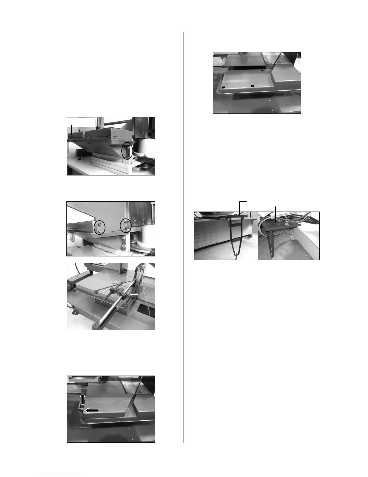
2.4 Installing the rear coolant return tray...................................................................................................2
2.5 Install the outlet tray, length stop device and mobile coolant trays. ....................................................3
2.6 Securing to foundation.........................................................................................................................3
2.7 Leveling the machine...........................................................................................................................3
2.8 Deactivation of machine.......................................................................................................................4
3DESCRIPTION OF MACHINE PARTS................................................................................................4
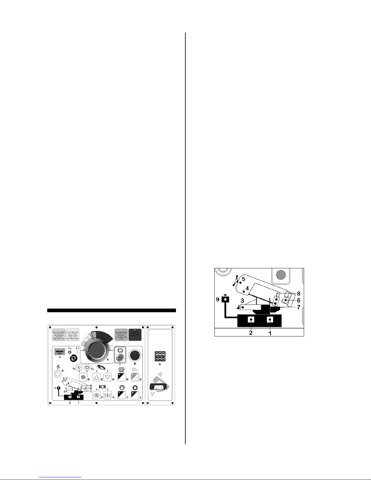
3.1 Control panel........................................................................................................................................4
3.2 Indicator lights......................................................................................................................................4
3.3 The saw bow........................................................................................................................................5
3.4 The vise system...................................................................................................................................5
3.5 The base..............................................................................................................................................5
3.6 Chip tray...............................................................................................................................................5
3.7 Blade broken micro switch...................................................................................................................5
3.8 Chip brush............................................................................................................................................5
3.9 Blade speed indicator ..........................................................................................................................5
3.10Open Blade Cover Safety Device........................................................................................................6
3.11Speed change dial ...............................................................................................................................6
3.12Blade angle scale.................................................................................................................................6
3.13Attached coolant device.......................................................................................................................6
4SET UP AND PRE-OPERATIONS......................................................................................................6
4.1 Adjusting the tungsten carbide guides.................................................................................................6
4.2 Thrust Roller Adjustment .....................................................................................................................7
4.3 Guide Roller adjustment ......................................................................................................................7
4.4 Adjusting the cutting precision.............................................................................................................7
4.5 Blade tracking adjustment (Manual blade tension type)......................................................................7
4.6 Blade tracking adjustment (Hydraulic blade tension type)...................................................................8
4.7 Placing the saw blade onto the drive wheel and flywheel....................................................................8
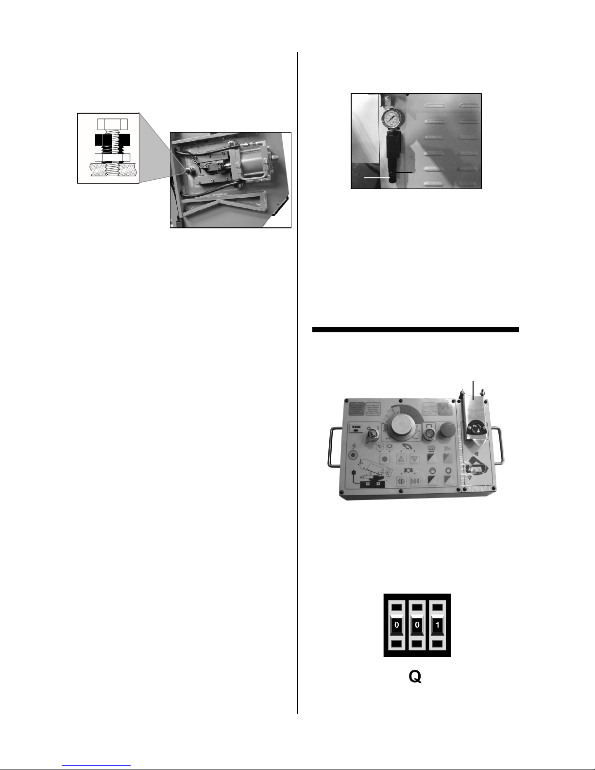
4.8 Hydraulic vise pressure........................................................................................................................8
5OPERATION PREPARATIONS...........................................................................................................8
5.1 Setting the stroke limit..........................................................................................................................8
5.2 Positioning the vise..............................................................................................................................9
5.3 Angle cutting ........................................................................................................................................9
5.4 Using the vise.......................................................................................................................................9
5.5 Adjusting the blade speed....................................................................................................................9
5.6 Changing the transmission belt............................................................................................................9
5.7 Selecting Automatic and Manual operation.......................................................................................10
5.8 Changing the blade (Manual blade tension type)..............................................................................10
5.9 Changing the blade (Hydraulic blade tension type)...........................................................................10
5.10Laser guide device (optional).............................................................................................................11
5.11Install the vertical press on the vise jaws for bundle cutting (optional)..............................................11
6OPERATION CYCLE.........................................................................................................................12
6.1 Operation cycle..................................................................................................................................12
6.2 Stopping or emergency stopping.......................................................................................................12
6.3 Automatic shutoff during machine operation .....................................................................................12
7ROUTINE AND SPECIAL MAINTENANCE.......................................................................................13
7.1 Daily maintenance..............................................................................................................................13
7.2 Weekly maintenance..........................................................................................................................13
7.3 Monthly maintenance.........................................................................................................................13
7.4 Six-monthly maintenance...................................................................................................................13
7.5 Oils for lubricating coolant..................................................................................................................13
7.6 Oil disposal.........................................................................................................................................13
7.7 Special maintenance..........................................................................................................................13
7.8 Changing gear oil...............................................................................................................................13
8TECHNICAL CHARACTERISTICS....................................................................................................14
8.1 Table of cutting capacity and technical details ..................................................................................14
8.2 NOISE TESTS ...................................................................................................................................14
2
Instruction Manual for BS-460AS (B035)
31/03/2016

- In the event of a power cut, the specific start-up
button must be reset.
1 ACCIDENT PREVENTION AND
SAFETY REGULATION - The machine has been tested in conformity with
point 20 of EN 60204
This machine has been designed to comply with
national and community accident- prevention
regulations. Improper use and/or tampering with
the safety devices will relieve the manufacturer of
all responsibility.
1.1 Advice for the operator
- Check, the line voltage is the same as the
voltage required by the machine’s motor.
- Check the efficiency of your electric supply and
grounding system; connect the power cable of
the machine to the socket and the ground lead
(yellow- green in color) to the grounding system.
- When the machine is in suspended mode (or
stopped) the blade must not move.
- Only the blade section used for cutting must be
kept unprotected. To remove guards to expose
more of the cutting blade adjust the blade
guides.
- It is forbidden to use the machine without its
shields
- Always disconnect the machine from the power
socket before blade change or carrying out any
maintenance job, even in the case of abnormal
machine operation.
- Always wear suitable eye protection.
- Never put your hands or arms into the cutting
area while the machine is operating.
- Do not shift the machine while it is cutting.
- Do not wear loose clothing like: shirts with
sleeves that are too long, gloves that are too big,
bracelets, chains or any other object that could
get caught in the machine during operation. Tie
back long hair.
- Keep the area free of miscellaneous object; i.e.
equipment, tools, etc…
- Perform only one operation at a time. Never
have several objects in your hands at the same
time. Keep your hands as clean as possible.
- All internal operations, maintenance or repairs,
must be performed in a well-lit area or where
there is sufficient light from extra sources to
avoid the risk of accidents.
1.2 The electrical equipment according to
European Standard" CENELEC EN
60204-1"
1.3 Warning labels
- The electrical equipment ensures protection
against electric shock as a result of direct or
indirect contact. The active parts of this
equipment are housed in a box to which access
is limited by screws that can only be removed
with a special tool; the parts are fed with
alternating current as low voltage (24V). The
equipment is protected against splashes of
water and dust.
- Protection of the system against short circuits is
ensured by means of rapid fuses and grounding;
in the event of a motor overload, protection is
provided by a thermal probe.
Replace warning labels if they become obscured
or removed.
- Keep hands and other body parts away from a
running blade.
- Do not open the blade cover while machine is
running.
- Do not store combustible materials near or
around machine.
- Always wear approved safety glasses/face
shields while using this machine.
- Keep machine guards in place at all times.
- Do not wear gloves.
- Remove loose clothing and confine long hair.
- Keep the work area clean and free
miscellaneous objects.
1.4 Emergencies according to European
Standard “CENELEC EN 60204-1”
- In the event of incorrect operation or a danger
condition, the machine may be stopped
immediately by pressing the red mushroom
shaped button.
NOTE: Resetting of machine operation after each
emergency stop requires resetting the emergency
stop button.
3
Instruction Manual for BS-460AS (B035)
31/03/2016

2 MACHINE TRANSPORTATION AND
INSTALLATION
2.1 Machine dimensions
2.2 Transporting the machine
2.3 Minimum requirements for housing the
machine
- Main voltage and frequency must comply with
the machine’s motor requirements.
- Environment temperature should fall within
(-10ºC to + 50 ºC).
- Relative humidity cannot be over 90%.
2.4 Installing the rear coolant return tray
The rear coolant-return tray must be installed after
the machine is set in place. Install the coolant
return trays first.
Installing three channeled L-bracket
Install three channeled L-bracket to the back of
the machine stand. Attaching the brackets
requires 6 hex head bolt, 6 spring washers, 6
washers, and 6 nuts.
Unpack your machine carefully, and use a crane
or forklift to set it in position. If a crane is used to
lift the machine, attach the lifting cable carefully to
the machine. Sufficient space should be left
around the machine to allow safe handling of
materials, inspection, and maintenance operations.
Take precautions to choose a location that will
keep the machine free of vibration and dust
caused by other machinery.
- Place a spring washer and washer on each hex
head bolt.
- Face the long side of the bracket up.
- Align the holes of short side of the bracket to the
machine panel’s holes.
- Place the 2 hex head bolts and their washers
through each bracket and machine panel.
- Use a nut on the inside of the machine stand to
secure each hex head bolt.
securing the rear tray
Attaching the trays requires 6 hex head bolt, 6
spring washers, 6 washers, and 6 nuts.
Bolt
point
- Arrange the tray rims to facing up and away
from the machine.
- Place the rear return tray onto brackets at the
back of the machine.
- Align the holes of the rear tray and the six-
channeled L-brackets.
- Place 6 hex head bolts through the holes of the
trays and brackets.
- Secure each hex head bolts with a washer,
spring washer, and hex nut.
4
Instruction Manual for BS-460AS (B035)
31/03/2016

Remove mobile cover by lift handle up and pull it
out from the base as showing direction.
2.5 Install the outlet tray, length stop device
and mobile coolant trays.
Install the outlet tray and stop bar on to the
machine after setting up the machine already as
below steps:
1. Assemble the new outlet tray on to the
machine by screw in the four screws on the
both side as picture. Tighten the four screws
after make sure the top of outlet surface same
as table.
Outlet tray There are four slots on the cover base after
removing the mobile cover for this way miter
cutting.
Install the mobile cover to the four slots and push
it to the right side to secure it.
2. Install stop device on to the outlet tray at the
right side by tighten four screws.
3. If miter cutting on the front way or move the
vise to this side for another way miter cutting,
the movable cover on the left side can be
removed by pull handle up and out as arrow
direction to remove it from being cut.
4. They are two mobile coolant trays can be
moved and used in miter cutting on front and
rear side to prevent coolant spray on to the
floor.
Mobile coolant tray
2.6 Securing to foundation
Position the machine on a flat and level
foundation of reinforced concrete. Level machine
and anchor it to the foundation with anchor bolts.
Maintain a minimum distance of 800mm from the
rear of the machine to the wall. Position the
anchors using screws and expansion plugs or tie
rods sunk in cement.
2.7 Leveling the machine
The operating accuracy of all precision machinery
depends on the accuracy of the installation of the
machine. Manufacturing tolerance of the machine
can only be guaranteed if the machine is firmly
and properly installed. Once the machine is
lowered on the prepared foundation, machinist
levels should be used alternately on the vice slide
plates and work feed table, adjust the left to right
and front to back level of the machine with
leveling bolts.
- When leveling left to right level, adjust left side to
be approximately 3mm higher than the level of the
right side. This will provide proper return of the
cutting fluid. After proper leveling of the machine,
use anchor bolts to secure to the foundation.
Mobile cove
r
Caution: All leveling bolts should support the
weight the machine evenly
5
Instruction Manual for BS-460AS (B035)
31/03/2016

D. Operation mode switch – selects either
automatic or manual operation mode.
2.8 Deactivation of machine
If the machine is to be out of use for a long period,
it is advisable to proceed as follows: D1. Manual operation mode – press switch D until
the manual mode’s indicator light shows up.1) Disconnect from the power supply
2) Loosen the tension on the blade D2. Automatic operation mode – press switch D
until the automatic mode’s indicator light
shows up.
3) Release the bow return spring
4) Empty the coolant tank
5) Carefully clean and grease the machine E. Bow up switch – press to raise the saw bow
6) If necessary, cover the machine. F. Vise open switch – press to open the vise
Dismantling (due to deterioration and/or
obsolescence) G. Vise close switch – press to close the vise
H. Bow down switch – press to lower the saw
bowAs a General Rule,
If the machine is to be permanently demolished
and/or scrapped, divide the material to be
disposed of according to type and composition, as
follows:
I. Cycle start switch – press to begin operation
J. Stop switch – press to stop operation cycle
and return to start position
1) Cast iron or ferrous materials, composed of
metal alone, are secondary raw materials, so
they may be taken to an iron foundry for re-
smelting after having removed the contents
(classified in point 3).
2) Electrical components, including the cable and
electronic material (magnetic cards, etc.), fall
within the category of material classified as
being assimilated to urban waste according to
the laws of your local, state, or federal
government, so they may be set aside for
collection by the public waste disposal service;
3) Old mineral and synthetic and/or mixed oils,
emulsified oils and greases are considered
hazardous or special refuse, so they must be
collected, transported and disposed of at a
special waste disposal service.
NOTE: The standards and legislation concerning
refuse is in a constant state of evolution, therefore
is subject to changes. The user must keep
informed of the regulations at the time of disposal
as these may differ from those described above.
3 DESCRIPTION OF MACHINE PARTS
3.1 Control panel
K. Cutting feed rate – adjust the rate of cutting of
the saw bow.
L. Key lock power switch – to start or stop power.
L0. Power off switch – key switch to turn power
off
L1. Power on switch – key switch to turn power
on
M. Emergency Stop Button – Press to stop all
machine functions
N. Blade tracking switch – press to activate
blade tension and set the blade tracking.
O. Coolant start switch – press to activate or stop
coolant flow
P. Counter – counts the pieces cut, press the
button to reset units to zero.
Q. Stroke height switch – limits the stroke height
to eliminate the wasted motion and time.
Maximum height limit is 330mm.
3.2 Indicator lights
A. Main connect switch – main power
B. Main power indicator light – indicates that main
power is active
C. Hydraulic flow control start switch – actives
hydraulic power
1. Coolant pump warning light
2 Hydraulic pump warning light
3. Vise pressure warning light
4. Open blade cover warning light
5. Broken blade warning light
6. Main motor warning light
7. Lower stroke limit indicator light
8. Upper stroke limit indicator light
9. Emergency stop indicator light
6
Instruction Manual for BS-460AS (B035)
31/03/2016

3.3 The saw bow
Machine parts consisting of drive members (gear
motor, variable speed motor, and flywheels),
tightening and guide (blade tightening slide, blade
guide blocks) of tool.
3.4 The vise system
A hydraulic vise is used for clamping work
material. Each of the vises has a miter slot, which
is good for the right or left side’s angle cutting to
60°.
3.5 The base
The base is the structure supporting the saw bow
(the bow pivot point and respective blocking
system), the vises, and containing chip tray and
coolant system.
3.6 Chip tray
3.7 Blade broken micro switch
This machine is equipped with automatic power
shut-off safety device to prevent any further
damage when a blade has been broken. There is
a reduction in tension when an adjustment bolt
actuates micro switch’s plunger. To keep the
micro switch in proper contact with the blade’s
tension. An adjustment of the actuator bolt is
required.
3.8 Chip brush
This model has a powered chip brush driven by
an axle transfer from the drive motor. The chip
brush is designed to clean the blade thus
prolonging the life of the blade.
3.9 Blade speed indicator
A digital display indicates the blade speed in MPM.
This works in conjunction with speed changing
dial to give you precise control of blade speed.
Removable chip tray for capture of chips and
debris.
7
Instruction Manual for BS-460AS (B035)
31/03/2016

3.10 Open Blade Cover Safety Device
When blade cover is open, close the blade cover
as instructed below:
1. Use one hand on the cover handle to hold
the blade cover.
2. Use the other hand to push in the safety
plate (Fig. A), so the bracket will release (Fig.
B).
3. Lower the cover down slowly and carefully.
3.11 Speed change dial
The speed change dial adjusts the variable speed
transmission so that there is a change in blade
speed. Change only while blade is moving.
This machine has a variable speed transmission
using a variable pulley - system. The speed is
changed by rotating the speed changer dial to
adjust the width of the pulley discs. When
compressed, the pulley discs cause the belt to
ride the outer edge of pulley discs and changing
the speed. The speed must be changed while belt
is moving.
3.12 Blade angle scale
3.13 Attached coolant device
An attached coolant device that is screwed on the
front vise jaw for supply enough coolant to the
cutting material. This device can be unscrewed,
and move to the rear vise jaw for easy both side
miter cutting.
4 SET UP AND PRE-OPERATIONS
4.1 Adjusting the tungsten carbide guides
The blade is guided by the upper ball bearings,
side ball bearings, and tungsten carbide guides.
The scale indicates the cutting angle of the blade.
The scale has preset stops at every 15.
Ball bearing
Ball bearing
Tungsten carbide guides
- When ready to cut the work piece, the carbide
guide must be adjusted by adjusting the screws
to properly compressed blade. The tungsten
carbide blades should touch, but not pinch the
blade.
- For moving the blade guide posts or changing
blade, the tungsten carbide guides should be
released by using the adjusting screw.
In case the blade needs to be replaced, make
sure to always install 1.3mm thick blade.
8
Instruction Manual for BS-460AS (B035)
31/03/2016

4.2 Thrust Roller Adjustment
1. Disconnect machine from the power source.
2. Loosen two hex socket cap screws (X)
3. Move guide seat (Y) up or down until a
clearance of .003" to .005" between back of
blade and thrust roller is obtained.
4. Tighten two hex socket cap screws (X).
5. Repeat for other blade guide assembly.
6. Connect machine to the power source.
4.3 Guide Roller adjustment
4.4 Adjusting the cutting precision
Note:Only bearing (A) is adjustable. Bearing (B)
is fixed.
1. Disconnect machine from the power source.
2. Loosen blade guides by loosening guide
adjustment screw (Z4.2).
3. Loosen locking screws (A) by using a hex
wrench.
4. Adjust the eccentric bushings with a
combination wrench until the ball bearings are
snug to the blade (A)
Note: blade should travel freely up and down
between the ball bearings. do not pinch the
blade.
5. Tighten locking screws (A).
6. Connect machine to the power source.
X1
Y
X
Z
X
The cutting precision has been set at the factory.
This adjustment should only be accomplished by
a qualified personnel that are familiar with this
type of adjustment.
- Disconnect the machine from power supply.
- Loosen the adjusting bolts (X) slightly, if needed.
- Use the setscrews (X1) to adjust the direction of
the guide blocks.
- After adjusting, tighten the adjusting bolts (X).
4.5 Blade tracking adjustment (Manual
blade tension type)
This adjustment must be accomplished by
qualified personnel that are familiar with this type
of adjustment and the dangers associated with it.
V
Blade tracking has been set at the factory and has
no adjustment required. If a tracking problem
occurs, adjust the machine as follows:
- Raise saw arm to the proper position.
- Locate tracking adjustment screw (V) on the
front of the saw blade, flywheel side.
- Reduce the blade tension a little.
- Turn the tracking adjustment screw (V) to adjust
the saw blade ride.
- Re-tension the blade tension.
- Connect the machine power to run the blade for
1-2 minutes. Then stop the machine operation.
- Remove the blade guides and open covers to
check the blade tracking
- Close covers, replace the blade guides and
tighten the setscrews.
- If necessary, readjust it again.
9
Instruction Manual for BS-460AS (B035)
31/03/2016

4.6 Blade tracking adjustment (Hydraulic
blade tension type)
This adjustment must be accomplished by
qualified personnel that are familiar with this type
of adjustment and the dangers associated with it.
The blade tracking has been set by factory and
should not require any adjustment. If a tracking
problem occurred, adjust the machine as follows:
- Raise saw arm to a usable height.
- Disconnect the machine from the power source.
- Locate tracking adjustment bolt on the backside
of the saw bow behind the flywheel.
- Loosen hex cap screw C, located on the top of
the track-adjusting bolt A and tracking nut B .
- Either raising or lowering track-adjusting bolt A
accomplishes track adjusting.
- Tracking is set properly when the back of the
blade lightly touches the wheel flange. Note:
over tracking (allowing blade back to rub hard
against wheel flange) will damage the blade
wheels and blade.
- Tighten hex cap screw C and tracking nut B.
- Connect machine to the power source.
4.7 Placing the saw blade onto the drive
wheel and flywheel
- Disconnect from power supply
- Remove the blade guards
- Turn the blade tension handle counter-
clockwise, to fully loosen the flywheel.
- Open the blade cover and place the saw blade
onto the race of the drive wheel and flywheel.
*Check the cutting direction of the saw blade.
- Insert the saw blade into the rollers of the left
and right blade guide.
- The back edge of the saw blade should make
contact with the flange of the drive and flywheel;
turn clockwise the blade tension handle to
tighten the saw blade, until the blade is properly
tensioned.
- Replace the blade guards.
- Use the blade running switch 3.1N to check the
proper ride of the blade.
4.8 Hydraulic vise pressure
The hydraulic vise pressure can be monitored and
adjusted by a pressure gauge on the base of the
machine. The normal pressure is set at
35kgs/cm2. This is good for most solid firm
materials. For softer, hollow, or pipe materials
reduce the pressure to over 25kgs/cm2. Other
materials may require different clamping force.
The clamping pressure may be adjusted by a
knob at the base of the pressure gauge assembly.
C
A
B Z1
Z
- Start by pressing the vise close switch (3.1G)
continuously in manual mode to have the vise
clamp onto a work piece.
- Next, unlock the fluted knob (Z) by releasing
fluted lock nut (Z1).
- Turn the fluted knob (Z) counterclockwise to
decrease the pressure, clockwise to increase
the vise pressure.
- Lock the fluted nut (Z1) after adjustment.
5 OPERATION PREPARATIONS
5.1 Setting the stroke limit
Waterproof cover
The numerical bow stroke height adjusting switch
is covered with waterproof cover, set the bow
height need to open the cover, after setting bow
raise up stroke already, cover the cover to prevent
the coolant permeate into the switch to cause the
switch damaged.
10
Instruction Manual for BS-460AS (B035)
31/03/2016

- Check that the saw bow is raised to clear the
vise fixed vise jaw.
This machine is equipped with a numeral switch Q
to set the saw bow an efficient return height. If
cutting lots of pieces, set the saw bow’s return
stroke height switch according to the work-piece’s
diameter will reduce the overall time of one
operation cycle.
- Turn off power.
- Unlock the saw bow by using the lock lever
under the machine bench.
- Rotate the saw bow to the desired cutting angle.
Refer to the scale to determine the proper angle.- Lock the cutting angle in place by using the lock
lever.
5.2 Positioning the vise
When cutting angles, the relocation of the vise is
necessary to prevent the blade from cutting the
hydraulic vise. - Next, adjust the location of the vise to avoid
contact with the blade.
Adjusting the hydraulic vise for angle cutting
.- The saw bow must be raised to clear the vise.
- Unlock the hydraulic vise lock handle.
- Push the hydraulic vise toward other side.
- Visually check clearance of the blade and saw
bow against the hydraulic vise. Readjust the
position if necessary.
- Lock the hydraulic vise in position using its lock
handle.
5.3 Angle cutting
5.4 Using the vise
The hydraulic vise operates automatically and can
be controlled using the control panel. Use the
vise open switch 3.1F and vise close switch 3.1G
to open and close the vise. Power must be active.
Hydraulics must be active.
5.5 Adjusting the blade speed
*Blade speed must be changed while belt and
blade are moving.
Vise lock handle - Check that the machine is running and blade is
moving.
- Rotate the speed change dial 3.10 and check
the speed indicator 3.9 for desired speed. Turn
the dial clockwise to raise blade speed, and turn
the dial counter clockwise to reduce blade
speed. The speeds available are 26-80MPM
(32-96FPM).
5.6 Changing the transmission belt
Over time and due to normal wear and tear the
pulley belt will need to be changed.
The machine can cut angles up to 60in both
directions
Lock lever
Angle scale
11
Instruction Manual for BS-460AS (B035)
31/03/2016

- Disconnect the machine from power supply.
- Open the belt cover. Remove 4 screws from the
top. Remove 1 screw from the front. Remove 8
screws from the cover.
- Turn the dial counter-clockwise to open the
pulley discs and loosen the belt.
- Replace the belt.
- Turn the dial to pretension the belt.
5.7 Selecting Automatic and Manual
operation
- To select manual mode, press operation mode
switch 3.1 D. - Close all covers and guards and fasten securely.
Connect machine to power and run the blade
freely for 1-2 minutes.
- Check the indicator light 3.1 D1 lightening.
- To select automatic operation, press operation
mode switch 3.1 D. - Turn the power off and recheck the blade
tension and chip brush. If further adjustment is
necessary disconnect the saw from the power
source, make adjustments, and re-connect the
power.
- Check the indicator light 3.1 D2 lightening.
5.8 Changing the blade (Manual blade
tension type)
5.9 Changing the blade (Hydraulic blade
tension type)
- Raise the saw bow approximately 6” in height.
- Disconnect the machine from the power source.
- Remove both blade guides from the blade guide
blocks and cover.
- Loosen the cover’s lock screws and open the
covers.
- Take off the chip brush device by loosen it’s
screws.
- Loosen left blade guide arm’s lock handles and
slides it to the right side as far as possible.
- Release blade tension by turning the blade
tensioning handle counter-clockwise until blade
is free.
- Remove the old blade from both wheels and out
of each blade guide.
Caution: Even dull blades are sharp to the
skin! Use extra caution handling band saw blades!
- Position the blade and making sure that the
teeth are pointed downward in the cutting
direction.
- Position the blade on the wheels. Make sure
back of the blade rests lightly against the wheel
flange of the both wheels. Twist blade slightly
to allow it to slip into guides.
- Tension the blade to the tension indicator
shown line 460DSA. Replace the chip brush
device so that it touches the blade and tighten
setscrew.
- Raise the saw bow approximately 6” in height.
- Disconnect the machine from the power source.
- Remove both blade guides from the blade guide
blocks and cover.
- Loosen the cover’s lock screws and open the
covers.
- Lower the chip brush device away from the
blade by loosen the wing nut.
- Loosen left blade guide arm’s lock handles and
slides it to the right side as far as possible.
- Release blade tension by turning the blade
tension handle counter-clockwise to the loosen
position that blade will free.
WARNING
Disconnect the machine from the power
source before making any adjustments or
repairs! Failure to comply may result in
serious injury!
!
!WARNING
Disconnect the machine from the power
source before making any adjustments or
repairs! Failure to comply may result in
serious injury!
Wing nut
!
12
Instruction Manual for BS-460AS (B035)
31/03/2016

- Remove the old blade from both wheels and out
of each blade guide.
Caution: Even dull blades are sharp to the
skin! Use extra caution handling band saw
blades!
- Position the blade and making sure that the
teeth are pointed downward in the cutting
direction.
- Position the blade on the wheels. Twist blade
slightly to allow it to slip into guides.
- Turn the blade tension handle to the tighten
direction a little bit and check the blade to make
sure back of the blade rests lightly against the
wheel flange of the both wheels.
- Turn the blade tension handle to the Tighten
position to tension the blade by the tension
cylinder automatically.
- Replace the chip brush device so that it touches
the blade and tighten setscrew.
- Close all covers and guards and fasten securely.
Connect machine to power and run the blade
freely for 1-2 minutes.
- Turn the power off and recheck the blade
tension and chip brush. If further adjustment is
necessary disconnect the saw from the power.
- Close all covers and guards and fasten securely.
Connect machine to power and run the blade
freely for 1-2 minutes.
- Turn the power off and recheck the blade
tension and chip brush. If further adjustment is
necessary disconnect the saw from the power
source, make adjustments, and re-connect the
power.
5.10 Laser guide device (optional)
The laser guide has been set correctly before
shipment. The laser guide - line works when
machine power on, the red line will align and close
with the blade.
if any situations have to readjust Laser device,
see below pictures.
- A screw for moving the device forward or
backward.
- B screw for moving the device downward or
upward.
- Loosen C thumb knob for adjust the device
angle.
Blade tension handle
A
5.11 Install the vertical press on the vise jaws
for bundle cutting (optional)
- Standard press capacity (W x H) 250~485 x
150~240 mm. Vise plates height 240 mm
- Special press capacity (W x H) 250~485 x
300~400 mm. Vise plates height 400 mm
- Open the vise more than 250mm.
- Attach and Tighten posts bolts’ (A) on to vises.
Then attach the vertical press to the top of the
post bolts. Connect the Hydraulic connector (B).
- Attach the nuts (H) on to the posts, but do not
make the nut (H1) on moveable vise jaw too
tight. *Otherwise, the vise won’t be able to
clamp the work piece or the post bolts will be
damaged.
- Adjust the vise press (E) to sit approximately 5-
8mm above the work piece. Loose nut (C) and
rotate the bolt (D) to raise or lower the vise
press (E).
- Adjust the vise press width to fit the work piece
size. Loosen screws (F) on both sides of the
vise press then move press extender bars (G)
desired width.
Loosen
Tighten
!
Laser guide device
C
B
B
D
HCH1
AE
F G
13
Instruction Manual for BS-460AS (B035)
31/03/2016

- Turn OFF the hydraulic pump.
- Attach the hydraulic hose to connecter (B) and
then attach the quick link connecter (J) to the
90-degree fitting.
- Switch ON the hydraulic pump.
6 OPERATION CYCLE
6.1 Operation cycle
6.2 Stopping or emergency stopping
There are two ways to stop the machine in an
event of an emergency or improper operation.
J - For most situations, use the stop switch 6.1 J.
Using the stop switch 6.1 J will not reset the
controls and your operation setting. The blade
and drive motor will stop. Then the saw bow will
rise to the start position. Adjustments can be
made.
- Use the cycle start switch to continue the cutting
cycle.
- For unsafe and emergency conditions use the
emergency stop button 6.1 M. Using
emergency stop button 6.1 M will stop the
machine in last position. The motor and
hydraulic will stop and control setting will be
reset.
- To restart, the emergency stop button 6.1 M
must be turned to release from the pressed
position. Then the operation cycle 6.1 must
restarted.
6.3 Automatic shutoff during machine
operation
If there are any improper operation or situation,
the machine is designed to automatically shut off
during the operation cycle to prevent any further
damage from occurring.
- If the hydraulic pump is on and the machine has
not been active for 5 minutes, the power will be
shut off.
- If the time take to clamp the vise is over 40 sec,
the power will shut off. The vise pressure warning
light will flash in warning.
- After cutting the saw bow has taken more than
40 sec to rise to the start position, the power will
shut off. The upper stroke-limit indicator light will
flash in warning.
- Turn on the main connect switch A. on the door
of electrical box.
- Turn the key to automatic operation mode L1 to
unlock the machine. The indicator light B should
be lit. - After pressing the start button, the vise clamps
the work piece, and saw bow begins cutting. If
the cutting time is unable to finish within 90
minutes, the lower stroke limit indicator will flash
in warning and the power will be shut off.
- Start the hydraulic system, use switch C.
- Press the selector D to manual operation mode
D1, and its indicator light will be lit.
- Raise the saw bow, Use bow up switch E. If any of the above situations occurs, reset the
machine by pressing 6.1D. This will change the
operation mode – manual or automatic.
- Open the vise, use vise open switch F.
- Load the working material.
- Secure the material, use the vise close switch G.
- Base on the diameter of the material; set the
saw bow’s height Q.
- Choose the blade speed appropriate for the
material.
- If cutting many pieces, set the saw bow return
stroke height.
- Select the operation cycle mode 6.1 D2 to press
the selector 6.1 D. The indicator light will be lit.
- Restart the hydraulic system. Press the
hydraulic start switch 6.1 C. .
- Start operation by using the start switch 6.1 I.
- The digital display 6.1 P will present pieces cut.
- When the cutting operation is finished the saw
bow will automatically rise to the preset height
ready for the next operation.
14
Instruction Manual for BS-460AS (B035)
31/03/2016

7 ROUTINE AND SPECIAL
MAINTENANCE
The maintenance jobs are listed below, divided
into daily, weekly, monthly and six-month intervals.
If the following operations are neglected, the
result will be premature wear of the machine and
poor performance.
7.1 Daily maintenance
- Give general cleaning to the machine to remove
accumulated shavings.
- Clean the lubricating coolant drain hole to avoid
excess fluid.
- Top off the level of lubricating coolant.
- Check blade for wear.
- Rise of saw frame to top position and partial
slackening of the blade to avoid useless yield
stress.
- Check functionality of the shields and
emergency stops.
7.2 Weekly maintenance
- Thoroughly clean the machine to remove
shavings, especially from the coolant tank.
- Removal of pump from its housing, cleaning of
the suction filter and suction zone.
- Clean the filter of the pump suction head and
the suction area.
- Use compressed air to clean the blade guides
(guide bearings and drain hole of the lubricating
cooling).
- Clean flywheel housings and blade sliding
surfaces on flywheels.
7.3 Monthly maintenance
- Check the tightening of the drive wheel screws.
- Check that the blade guide bearings on the
heads are perfect running condition.
- Check the tightening of the screws of the motor,
pump, and accident protection guarding.
7.4 Six-monthly maintenance
- Test the continuity of the equipotential
protection circuit.
7.5 Oils for lubricating coolant
Considering the vast range of products on the
market, the user can choose the one most suited
to their own requirements, using as reference the
type SHELL LUTEM OIL ECO. THE MINIMUM
PERCENTAGE OF OIL DILUTED IN WATER IS 8
- 10 %.
7.6 Oil disposal
7.7 Special maintenance
Special maintenance must be conducted by
skilled personnel. We advise contacting your
nearest dealer and/or importer. Other protective
and safety equipment, devices (of the reducer),
the motor, the motor pump, and other electrical
components also require special maintenance.
7.8 Changing gear oil
The gear box requires periodic changing of oil.
The oil must be changed by the first 6 months of a
new machine and every year thereafter.
The disposal of these products is controlled by
strict regulations. Please see the Chapter on
"Machine dimensions Transport - Installation" in
the section on Dismantling.
- To change the gear box oil
- Lower the saw bow to horizontal position.
- Disconnect the machine from the power source.
- Release the drain hold (R) to draw off gear oil by
- loosening the hex head screw (S).
- Open fill hole (T) by releasing hex head screw (U)
- Replace the screw (S) after oil completely flows
off.
- Filling in gear oil from T hole, until oil be sight
from the visual glass.
- Replace hole using the fill hole (T).
- Replace hex head screw (U)
T, U
R, S
15
Instruction Manual for BS-460AS (B035)
31/03/2016

8 TECHNICAL CHARACTERISTICS
8.1 Table of cutting capacity and technical
details
14
8.2 NOISE TESTS
The test was held under environmental noise levels of 65db. Noise measurements with the machine
operating unload was 71db. Noise level during the cutting of mild carbon steel was 73db.
NOTE: with the machine operating, the noise level will vary according to the different materials being
processed. The user must therefore assess the intensity and if necessary provide the operators with the
necessary personal protection, as required by Law 277/1991.
16
Instruction Manual for BS-460AS (B035)
31/03/2016

17
Instruction Manual for BS-460AS (B035)
31/03/2016

18
Instruction Manual for BS-460AS (B035)
31/03/2016

19
Instruction Manual for BS-460AS (B035)
31/03/2016

PART LIST
Part
No. Description Size No. Q’ty Part
No. Description Size No. Q’ty
1 Base 1 54 Fuse Seat 10x38-1P 2
2 Hex. Cap Bolt M8x20 12 55 Fuse Seat ASK2S/(5X20-1P) 3
3 Spring Washer M8 12 55A Fuse Seat (Not shown, Non CE) 6X30-1P 3
4 Washer M8 12 56 Transformer CE-250VA 1
5 Supporter 1 57 Relay PC Board M1-RLY 1
6 Set Screw M6x6 2 58 Connector PC Board WT-M3-TL 1
7 Hex. Socket Cap Screw M6x12 2 59 Dual Terminal Connector ASL-TD-015H 10
7-1 Spring Washer M6 2 60 Fuse Seat 10x38-1P 3
8 Fixing Bracket 3 61 Ground Terminal Connector AVK10T 1
8-1 Fixing Bracket (RF) 1 61A Ground Terminal Connector
(Not shown, Non CE) HT-4E 1
8-2 Fixing Bracket 2 62 Terminal Connector AVK10 3
9 Nut M8 12 62A Terminal Connector
(Not shown, Not CE) HT-10 3
10 Spring Washer M8 12 63 Grounding Plate G-8P 1
11 Washer M8 12 64 Overload Contactor ABB-TA25DU
7.5~11A 1
12 Coolant Tray (L) 1 64A Overload Contactor
(Not shown, Non CE) NTH-8~11A 1
12-1 Coolant Tray (R) 1 65 Overload Connector ABB-TA25DU
2.2~3.1A 1
13 Hex. Cap Bolt M8x20 12 65A Overload Relay
(Not shown, Not CE) NTH-1.8~2.5A 1
14 Chip Drawer 1 67 Electric Box Cover 1
15 Side Coolant Tray 1 68 Power Switch (Upper) YMXN6 1
16 Washer M8 2 69 Washer M6 1
17 Spring Washer M8 2 70 Spring Washer M6 1
18 Hex. Cap Bolt M8x16 2 71 Hex. Socket Cap Screw M6x30 1
19 Coolant Pump 1 72 Hinges Ø8x50 2
20 Hex. Cap Bolt M6x12 2 73 Main PC Board WT-M1 1
21 Washer M6 2 74 Control Panel 1
22 Pump Plate 1 74-1 Control PCB 1
23 Button Head Socket Screw M6x12 2 75 Counter 1
24 Plate 1 76 Button Head Socket Screw M5x8 10
25 Button Head Socket Screw M6x8 4 77 Key Lock Power Switch 1
37 Hydraulic Unit 1 78 Cutting Feed Rate 1
38 Hex. Cap Bolt M8x16 2 79 Cycle Start Switch 1
39 Front Plate 1 80 Emergency Stop Button 1
40 Button Head Socket Screw M6x8 4 81 Stroke Panel 1
41 Hex. Cap Bolt M16x60 4 81-1 Bow Height PCB 1
42 Nut M16 4 82 Stroke Height Switch 1
43 Rear Plate 1 83 Button Head Socket Screw M5x8 4
44 Button Head Socket Screw M6x8 4 84 Plate 1
45 Vise Pressure Adjusting Valve 1 85 Handle 2
46 Electrical Box 1 86 Button Head Socket Screw M5x8 4
47 Washer M6 4 87 Control Box 1
48 Hex. Socket Cap Screw M6x16 4 88 Cover 1
49 Electrical Plate 1 88-1 Round Head Screw M6x8 6
50 Hex. Socket Cap Screw M6x12 4 89 Control Box Bracket 1
51 Power Switch (Seat) XA323B/B-40A 1 89-1 Button Head Socket Screw M6x8 4
52 Contactor A9-40-00
(COIL: AC24V) 290 Swiveling Bracket 1
52A Contactor
(Not shown, Non CE) C09D10A7
(COIL: AC24V) 290-1 Hex. Socket Cap Screw M6x16 4
53 Contactor A12-30-10
(COIL: AC24V) 191 Hex. Cap Bolt M8x16 4
53A Contactor
(Not shown, Non CE) C12D10A7
(COIL: AC24V) 191-1 Spring Washer M8 4
1000622
20
Instruction Manual for BS-460AS (B035)
31/03/2016
Table of contents
Other Hafco Saw manuals

Hafco
Hafco BP-305 User manual

Hafco
Hafco BS-7DS User manual

Hafco
Hafco BP-255 User manual

Hafco
Hafco T4I BS-250 User manual

Hafco
Hafco VB-450 User manual

Hafco
Hafco BS-10S User manual

Hafco
Hafco TS250SC User manual

Hafco
Hafco VB-45 User manual

Hafco
Hafco BS-250 User manual

Hafco
Hafco MetalMaster CS-315C User manual

Hafco
Hafco BS-13LS User manual

Hafco
Hafco MetalMaster CS-350V User manual

Hafco
Hafco BP-480 User manual

Hafco
Hafco EB-270DSA User manual

Hafco
Hafco BS-7S User manual

Hafco
Hafco BP-430 User manual

Hafco
Hafco MetalMaster CS-315D User manual

Hafco
Hafco BS-7DS User manual

Hafco
Hafco BS-7DS User manual

Hafco
Hafco MetalMaster BS-5S User manual