Hafco MetalMaster BS-5S User manual

OPERATION MANUAL
Edition No : BS-5S-1
Date of Issue : 10/2020
Model. BS-5S
Order Code B003
SWIVEL HEAD METAL BAND SAW

2
OPERATION MANUAL
NOTE:
In order to see the type and model of the machine, please see the
specication plate. Usually found on the back of the machine. See
example (Fig.1)
Fig.1
METAL CUTTING BAND SAW
MACHINE
BS-5S
MODEL NO.
SERIAL NO.
DATE OF MANF.
DistributeD by
www.machineryhouse.co.nz
MACHINE DETAILS
NOTE:
This manual is only for your reference. Owing to the continuous improvement of the Hafco
Metalmaster machine, changes may be made at any time without obligation or notice. Please
ensure the local voltage is the same as listed on the specication plate before operating this
electric machine.

3
OPERATION MANUAL
C O N T E N T S:
1. GENERAL MACHINE INFORMATION
1.1 Specications.............................................................. 4
1.2 Includes Accessories................................................. 4
1.3 Identication............................................................... 5
2. SAFETY
2.1 General Metalworking Machine Safety............. 6
2.2 Specic Safety For Band Saws............................... 9
3. POWER SUPPLY
3.1 Electrical Requirements.......................................... 10
3.2 Full Load Current....................................................... 10
4. SETUP
4.1 Unpacking.................................................................... 11
4.2 Clean Up........................................................................ 11
4.3 Site Preparation.......................................................... 11
4.4 Lifting Instructions.................................................... 11
4.5 Assembly....................................................................... 12
4.6 Test Run......................................................................... 12
5. OPERATION
5.1 Operation Overview................................................. 13
5.2 Setting The Cutting Angle...................................... 14
5.3 Vertical Operation..................................................... 14
5.4 Changing The Blade................................................. 15
5.5 Blade Selection.......................................................... 15
5.6 Selecting Speeds....................................................... 17
5.7 Optional Accessories................................................ 18
6. MAINTENANCE
6.1 Schedule....................................................................... 19
6.2 Blade Guide Adjustment......................................... 19
6.3 Troubleshooting........................................................ 21
Spare Parts............................................................................ 22
Risk Assessment Sheets.................................................... 25

4
OPERATION MANUAL
1.1 SPECIFICATION
Order Code B003
MODEL BS-5S
Operation Type Swivel Head
Capacity Round @ 90º (mm) 125
Round @ 45º (mm) 80
Square @ 90º (mm) 125
Square @ 45º (mm) 75
Rectangle @ 90º (W x H) (mm) 200 x 125
Rectangle @ 45º (W x H) (mm) 125 x 72
Table Working Height (mm) 680
Cutting Head Beam Type Manual
Cutting Head Down Feed Control Fixed Spring Type
Vice Clamping Fixture Manual
Blade Steps / Speeds (m/mm) 10 - 29 - 50
Blade Size (L x W x T) (mm) 1727 x 12.7 x 0.65
Motor Power (kW / hp)) 0.375 / 0.5
Voltage / Amperage (V / amp) 240 / 10
Dimensions ( L x W x H) (mm) 995 x 420 x 1162
Weight (kg) 65
1.2 ACCESSORIES INCLUDED
1 x Adjustable length stop for repetition cutting
1 x Vertical cutting table included
1 x Band Saw Blade

5
OPERATION MANUAL
1.3 IDENTIFICATION
ABlade IVice Jaws
BPulley Cover JVice Crank Handle
CMotor KRear Material Support
DAuto O Tab LBlade Guide Bearing Assemblies
EON/OFF Switch MMovable Guide Bearing Support Clamp
FHorizontal Stop NBlade Tension Knob
GStand OBow Saw Lifting Handle
HLength Stop PTilting Tracking Mechanism
A
B
C
E
G
J
L
K
N
M
O
H
F
I
P
D

6
OPERATION MANUAL
DO NOT use this machine unless you have read this manual or have been instructed in the use
of this machine in its safe use and operation
This manual provides safety instructions on the proper setup, operation, maintenance, and
service of this machine. Save this manual, refer to it often, and use it to instruct other operators.
Failure to read, understand and follow the instructions in this manual may result in re or
serious personal injury—including amputation, electrocution, or death.
The owner of this machine is solely responsible for its safe use. This responsibility includes, but
is not limited to proper installation in a safe environment, personnel training and authorization
to use, proper inspection and maintenance, manual availability and comprehension, of the
application of the safety devices, integrity, and the use of personal protective equipment.
The manufacturer will not be held liable for injury or property damage from negligence,
improper training, machine modications or misuse.
WARNING
2.1 GENERAL METALWORKING MACHINE SAFETY
Always wear safety glasses or goggles.
Wear appropriate safety footwear.
Wear respiratory protection where required.
Gloves should never be worn while operating the machine, and only worn when
handling the work piece.
Wear hearing protection in areas > 85 dBA. If you have trouble hearing someone speak
from one metre (three feet) away, the noise level from the machine may be hazardous.
DISCONNECTION THE MACHINE FROM POWER when making adjustments or servicing.
Check and adjust all safety devices before each job.
Ensure that guards are in position and in good working condition before operating.
Ensure that all stationary equipment is anchored securely to the oor.
Ensure all machines have a start/stop button within easy reach of the operator.
Each machine should have only one operator at a time. However, everyone should know
how to stop the machine in an emergency.

7
OPERATION MANUAL
Ensure that keys and adjusting wrenches have been removed from the machine before
turning on the power. Appropriate storage for tooling should be provided.
Ensure that all cutting tools and blades are clean and sharp. They should be able to cut freely
without being forced.
Stop the machine before measuring, cleaning or making any adjustments.
Wait until the machine has stopped running to clear cuttings with a vacuum, brush or rake.
Keep hands away from the cutting head and all moving parts.
Avoid awkward operations and hand positions. A sudden slip could cause the hand to move
into the cutting tool or blade.
Return all portable tooling to their proper storage place after use.
Clean all tools after use.
Keep work area clean. Floors should be level and have a non-slip surface.
Use good lighting so that the work piece, cutting blades, and machine controls can be seen
clearly. Position any shade lighting sources so that they do not cause any glare or reections.
Ensure there is enough room around the machine to do the job safely.
Obtain rst aid immediately for all injuries.
Understand that the health and re hazards can vary from material to material. Make sure all
appropriate precautions are taken.
Clean machines and the surrounding area when the operation is nished.
Use proper lock out procedures when servicing or cleaning the machines or power tools.
DO NOT
×Do not distract an operator. Horseplay can lead to injuries and should be strictly prohibited.
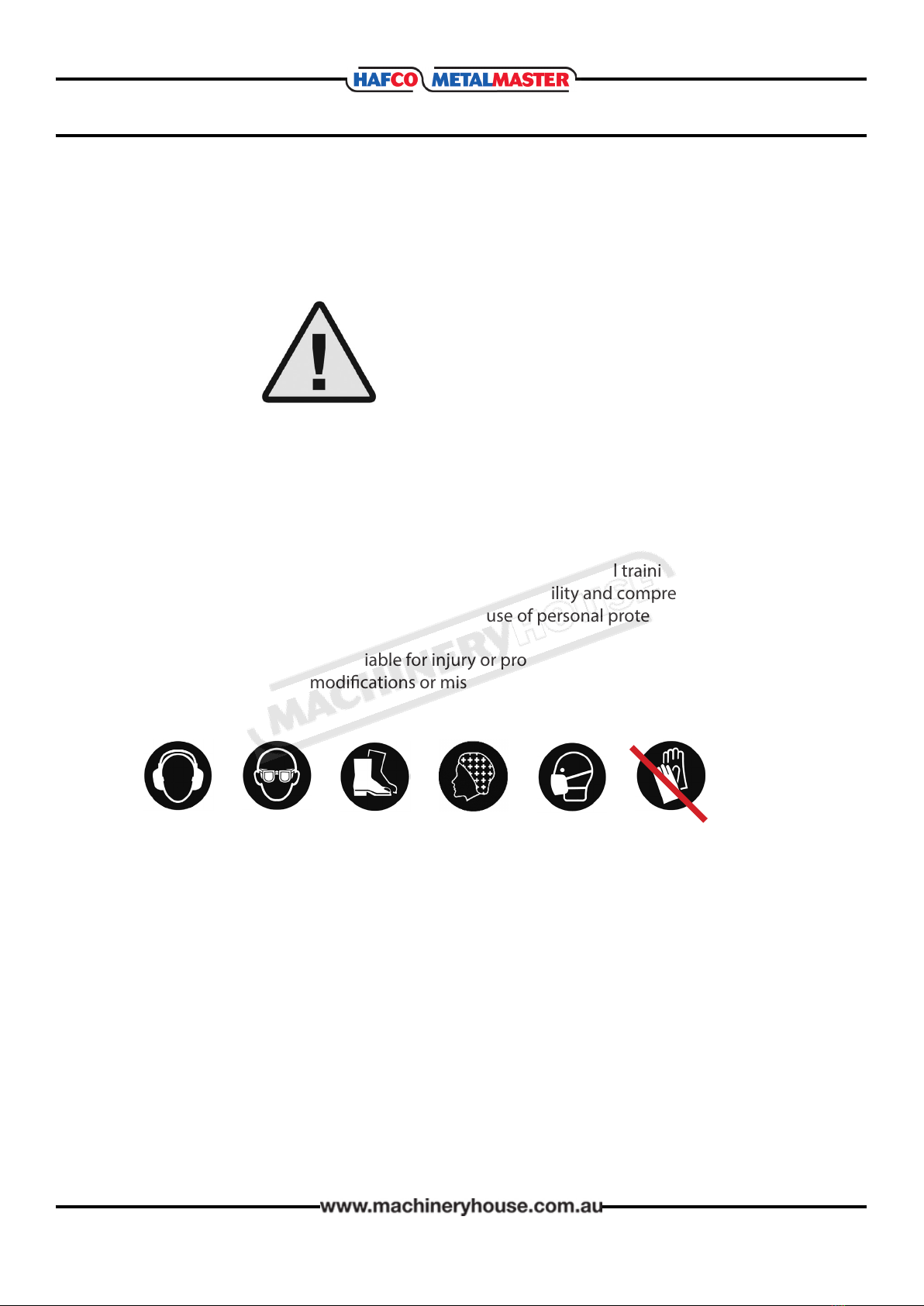
×Do not wear loose clothing, gloves, necktie’s, rings, bracelets or other jewellery that can be
come entangled in moving parts. Conne long hair.
×Do not handle cuttings by hand because they are very sharp. Do not free a stalled cutter
without turning the power o rst. Do not clean hands with cutting uids.
×Do not use rags or wear gloves near moving parts of machines.
×Do not use compressed air to blow debris from machines or to clean dirt from clothes.
×Do not force the machine. It will do the job safer and better at the rate for which it was
designed.
2.1 GENERAL METALWORKING MACHINE SAFETY Cont.
BEFORE OPERATING ANY MACHINE, TAKE TIME TO READ
AND UNDERSTAND ALL SAFETY SIGNS AND SYMBOLS.
IF NOT UNDERSTOOD SEEK EXPLANATION FROM TRADE
MAGAZINES OR AN EXPERIENCED OPERATOR.

8
OPERATION MANUAL
2.1 GENERAL METALWORKING MACHINE SAFETY Cont.
HAZARDS ASSOCIATED WITH MACHINES include, but are not limited to:
• Being struck by ejected parts of the machinery
• Being struck by material ejected from the machinery
• Contact or entanglement with the machinery
• Contact or entanglement with any material in motion
Health Hazards (other than physical injury caused by moving parts)
• Chemicals hazards that can irritate, burn, or pass through the skin
• Airborne items that can be inhaled, such as oil mist, metal fumes, solvents, and dust
• Heat, noise, and vibration
• Ionizing or non-ionizing radiation (X-ray, lasers, etc.)
• Biological contamination and waste
• Soft tissue injuries (for example, to the hands, arms, shoulders, back, or neck) resulting
from repetitive motion, awkward posture, extended lifting, and pressure grip)
Other Hazards
• Slips and falls from and around machinery during maintenance
• Unstable equipment that is not secured against falling over
• Safe access to/from machines (access, egress)
• Fire or explosion
• Pressure injection injuries from the release of uids and gases under high pressure
• Electrical Hazards, such as electrocution from faulty or ungrounded electrical
components
• Environment in which the machine is used (in a machine shop, or in a work site)
MACHINES ARE SAFEGUARDED TO PROTECT THE OPERATOR FROM INJURY OR DEATH WITH THE
PLACEMENT OF GUARDS. MACHINES MUST NOT BE OPERATED WITH THE GUARDS REMOVED
OR DAMAGED.

9
OPERATION MANUAL
2.2 SPECIFIC SAFETY FOR BAND SAWS
DO NOT use this machine unless you have been instructed in its safe use and
operation and have read and understood this manual
Safety glasses must be
worn at all times in work
areas
Long and loose hair must
be contained.
Gloves must not be
worn when using this
machine.
Sturdy footwear must be
worn at all times in work
areas
Close tting/protective
clothing must be worn
Rings and jewelery must
not be worn.
PRE-OPERATIONAL SAFETY CHECKS
PEnsure no slip/trip hazards are present in workspaces and walkways.
P. Check that all guards are in position.
PEnsure hydraulic damping mechanism functions.
PCheck that the blade is in good condition.
P. Ensure that blade speed, blade tension and blade tracking are properly adjusted.
PCheck coolant delivery system to allow for sucient ow of coolant.
P. Locate and ensure you are familiar with the operation of the ON/OFF starter and E-Stop.
PFaulty equipment must not be used. Immediately report suspect machinery.
OPERATIONAL SAFETY CHECKS
PLift the head of unit up and lock it in the upward position.
PSet the angle of the vice, or check it to ensure its squareness.
PClamp work piece rmly into the vice. Long material must be supported.
PAdjust blade guards to cover unused portion of blade.
PEnsure hands are away from the blade, and then turn the machine on.
PAllow the upper head assembly to come down slowly until the teeth are cutting the material.
PKeep hands away from the point of operation during cutting.
PTurn o the machine and bring it to a complete standstill if the blade is to be lifted out of an
uncompleted or jammed cut.
PStop the machine and bring it to a complete standstill before removing scrap pieces from
the vice area or making adjustments.
PStop the saw immediately if the blade develops a‘click’. Report it to your teacher.
PEnsure the cutting head is locked in the upward position before removing work piece.
AFTER OPERATION
PSwitch o the saw and reset all guards to a fully closed position.
PLeave the machine in a safe, clean and tidy state.
DO NOT
Pushing down on the cutting head while it is cutting
Leaving the machine running unattended

10
OPERATION MANUAL
The full-load current rating is the amperage a machine draws when running at 100% of the out-
put power. Where machines have more than one motor, the full load current is the
amperage drawn by the largest motor or a total of all the motors and electrical devices that
might operate at one time during normal operations.
Full-Load Current Rating for these machine at 240V is 3.5 Amps
It should be noted that the full-load current is not the maximum amount of amps that the
machine will draw. If the machine is overloaded, it will draw additional amps beyond the
full-load rating and if the machine is overloaded for a long period of time, damage, overheating,
or re may be caused to the motor and circuitry.
This is especially true if connected to an undersized circuit or a long extension lead. To reduce
the risk of these hazards, avoid overloading the machine during operation and make
sure it is connected to a power supply circuit that meets the requirements.
3.2 FULLLOAD CURRENT RATING
Place the machine near an existing power source. Make sure all power cords are protected from
trac, material handling, moisture, chemicals, or other hazards. Make sure there is access to a
means of disconnecting the power source. The electrical circuit must meet the requirements for
240V.
NOTE : The use of an extension cord is not recommended as it may decrease the life of electrical
components on your machine.
3.1 ELECTRICAL INSTALLATION
ELECTRICAL REQUIREMENTS
Nominal Voltage........................................240V
Cycle............................................................50 Hz
Phase..............................................Single Phase
Power Supply Circuit..........................10 Amps
Full Load Current................................3.5 Amps
(Full load current rating is also on the specication plate on the motor.)
3. POWER SUPPLY

11
OPERATION MANUAL
4.1 UNPACKING
This machine was carefully packaged for safe transport. When unpacking, separate all enclosed
items from packaging materials and inspect them for shipping damage. If items are damaged,
please contact your distributor.
NOTE: Save all the packaging materials until you are completely satised with the machine and
have resolved any issues with the distributor, or the shipping agent.
When unpacking, check the packing list to make sure that all parts shown are included. If any
parts are missing or broken, please contact the your distributor.
4 SETUP
The unpainted surfaces of the machine have been coated with a waxy oil to protect them from
corrosion during shipment. Remove the protective coating with a solvent cleaner or a citrus
based degreaser.
Optimum performance from your machine will be achieved when you clean all moving parts or
sliding contact surfaces that are coated with rust prevented products.
It is advised to avoid chlorine based solvents, such as acetone or brake parts cleaner, as they
will damage painted surfaces and strip metal should they come in contact. Always follow the
manufacturer’s instructions when using any type of cleaning product.
4.2 CLEAN - UP
4.3 SITE PREPARATION
When selecting the site for the machine, consider the largest size of workpiece that will be
processed through the machine and provide enough space around the machine for operat-
ing the machine safely. Consideration should be given to the installation of auxiliary equip-
ment. Leave enough space around the machine to open or remove doors/covers as required
for the maintenance and service as described in this manual.
It is recommended that the machine is anchored to the oor to prevent tipping or shifting. It
also reduces vibration that may occur during operation.
4.4 LIFTING INSTRUCTIONS
On the day that the machine arrives, make sure that a forklift or lifting device, with sucient
capacity is available to unload the machine from the vehicle. Ensure access to the chosen site
is clear and that doors and ceilings are suciently high and wide enough to receive the
machine.
This machine is extremely heavy.
Serious personal injury may occur if safe moving methods are not
followed. To be safe, you will need assistance and power equip-
ment when moving the shipping crate and removing the machine
from the crate.

12
OPERATION MANUAL
4.5 ASSEMBLY
The machine must be fully assembled before it can be
operated. First clean any parts that are coated in rust
preventative to ensure the assembly process can pro-
ceed smoothly. Although the main components of the
Hafco Metalmaster BS-5S are assembled at the factory,
some assembly is required.
1. Assemble the stand using the M8 x 10mm bolts,
8mm at and spring washers. (Fig. 4.1)
Note: At this time, tighten with a 14mm wrench
or socket just enough to secure the parts. Final
tightening will take place when the band saw has
been added to the stand.
2. Place the band saw on the stand, and secure it
to the stand using a M8 x 50 mm stud and nut at
the middle of the vice end and a M8 x 100 mm
in the middle of the motor end. (Fig. 4.2)
3. Check to see if band saw is relatively level, then
tighten all bolts and nuts.
4. Install the length stop shaft into side of band
saw, then lock it in place by using a Hex key to
tightening the set screw. (Fig. 4.3)
Fig. 4.1
4.6 TEST RUN
Once assembly is complete, test run the machine to ensure it is properly connected to the
power and that the guards and safety components are functioning properly.
If you nd an unusual problem during the test run, immediately stop the machine, disconnect it
from the power, and x the problem BEFORE operating the machine again.
The Troubleshooting table in the Maintenance section of this manual can help.
If no answer can be found contact your local distributer and report the fault.
Serious injury or death can result from using this machine BEFORE
understanding its controls and related safety information. DO NOT operate, or allow others to
operate, machine until the information is understood.
Hex Key
Fig. 4.3
Fig. 4.2

13
OPERATION MANUAL
5. OPERATION
This machine may perform many types of operations that are beyond the scope of this manual.
Many of these operations may be dangerous or deadly if performed incorrectly.
The instructions in this section are written with the understanding that the operator has the
necessary knowledge and skills to operate this machine. If at any time you are experiencing
diculties performing any operation, stop using the machine!
If you are an inexperienced operator, we strongly recommend that you read books, trade
articles, or seek training from an experienced operator before performing any unfamiliar
operations. Above all, your safety should come rst!
5.1 OPERATION OVERVIEW
The overview below provides the novice machine operator with a basic understanding of how
the machine is used during the operation, so that the machine controls and parts discussed
later in this manual are easier to understand.
Due to its generic nature, this overview is NOT intended to be an instructional guide.
A typical operation, consists of the following:
1. Select the work piece to be cut, making sure that the material is suitable to be cut.
2. Raise the head and swivel the head lock into place. (Fig. 5.1) Place the work-piece in the vise
and close the vice jaws to with in 1mm or 2 mm
3. Lower the head and measure the length from the blade to be
cut and then tighten the vise.
4. Check the V-belt position on the pulleys to ensure that it is
the correct cutting speed for the work piece.
Refer to blade speed table on page 17
5. Check the band saw blade to make sure that the number of
teeth are suitable for the material.
Refer to blade selection chart on page 16
6. Make sure that there is no obstructions and the workpiece
and band saw are stable. Wear safety glasses and suitable
footwear.
7. Start the machine, and wait for blade to reach its full speed.
(Fig. 5.2)
8 . Slowly lower the head until blade makes contact with the
work piece, then release the head and allow the weight of
the head to continue to lower blade into the work piece until
the cut is nished. Stop the machine, raise the head, and
remove the workpiece
Fig. 5.2
Fig. 5.1
K
Å
HeaD LocK

14
OPERATION MANUAL
5.2 SETTING THE CUTTING ANGLE
The band saw is tted with the capacity to cut angles
with the head being able to be swiveled up to 45° to
the right. (Fig. 5.3) To set the angle of the cut, raise the
bow saw to the highest point and hold with the head
lock.
Loosen the swivel lock lever (Fig. 5.4) and rotate the
head until the scale (Fig. 5.4) is at the angle required.
Tighten the swivel lock lever to keep the head in
place.
NOTE: Please note that the scale (Fig.5.4) is for
reference only and if the angle is required to be very
accurate then the angle should be checked with a
protractor after the cut.
5.3 VERTICAL OPERATION
The Model BS-5S can easily be set up for vertical
cutting operations to make cuts that are not a straight
cut through the entire workpiece, such as curves or
pattern cuts. To assemble the band saw for vertical
cutting:
1. DISCONNECT THE BAND SAW FROM THE POWER!
2. Remove the two at head screws and the blade
guide cover shown in Fig. 5.5.
3. Install the table and replace the two screws
removed in Step 2.
Fig. 5.3
swiveL LocK
Fig. 5.4
Fig. 5.5

15
OPERATION MANUAL
5.4 CHANGING THE BLADE
Blades should be changed when they become dull, damaged,
or when the teeth per inch does not suit the operation and
requires a dierent blade
To change the blade on the band saw:
1. DISCONNECT THE BAND SAW FROM POWER!
2. Raise the head of the band saw to the vertical position,
then remove wheel access cover. (Fig. 5.6)
3. Loosen the tension knob and slip blade o wheels.
(Fig. 5.7)
4. Install new blade through both blade guide bearings,
as shown in Fig. 5.8, around bottom wheel.
5. Hold the blade around bottom wheel with one hand and
slip it over the top wheel with the other hand, keeping the
blade between the blade guide bearings.
NOTE: It is sometimes possible to ip blade inside out, in which
case the blade will be installed in wrong direction. Check to
make sure the blade teeth are facing toward the workpiece.
6. Once the blade is around both wheels, adjust the position
of the blade so the back of the blade is against shoulder of
wheels.
7. Tighten tension knob so the blade will not slip on the
wheels upon start up.
8. Ret the belt access cover.
9. Connect the band saw to the power source.
Fig. 5.6
Fig. 5.7
bLaDe tension
Knob
bLaDe guiDe
bearings
Fig. 5.8
Blades are very sharp. If not careful serious injury can result from
touching the blades with bare hands. Leather work gloves should be worn when handling
these blades

16
OPERATION MANUAL
5.5 BLADE SELECTION
Band saw tooth size is determined by the size of the cross section to be cut. In general cutting
thinner sections requires more teeth per inch, thicker sections require coarser pitches, or less
teeth per inch. To select an appropriate tooth size please refer to the table immediately below
unless material to be cut is a tube, in which case refer to the larger table below. For general pur-
pose cutting use a constant pitch blade, for more aggressive production cutting of harder to cut
materials use a variable pitch blade.
SOLID SECTION
SEcTION SIzE (MM) cONSTANT PITch (TPI) VARIAbLE PITch (TPI)
UPTO 10 24 or 18 14/18 or 10/14
10 - 15 14 8 - 12
16 - 30 10 6 - 10
31 - 50 8 5 - 8
51 - 80 6 4 - 6
81 - 120 4 3 - 4
121 - 200 3 1 - 3
OVER 200 2 or 1.25 1.4 - 2 or 0.8 - 1.3
WALL
ThIckNESS
(MM)
OUTSIdE dIAMETER Of TUbE OR MAxIMUM PROfILE SEcTION LENgTh (MM)
20 40 60 80 100 120 150 200 300 500 600 700 800
214 14 14 14 14 14 10-14 10-14 8-12 8-12 6-10 5-8 5-8
314 14 10-14 10-14 10-14 10-14 8-12 8-12 6-10 6-10 5-8 5-8 5-8
414 14 10-14 10-14 8-12 8-12 6-10 6-10 5-8 5-8 4-6 4-6 4-6
514 10-14 10-14 8-12 8-12 6-10 6-10 5-8 5-8 4-6 4-6 4-6 4-6
614 10-14 10-14 8-12 8-12 6-10 6-10 5-8 5-8 4-6 4-6 3-4 3-4
816 10-14 8-12 8-12 6-10 6-10 5-8 5-8 4-6 4-6 3-4 3-4 3-4
10 8-12 8-12 6-10 6-10 5-8 5-8 4-6 4-6 3-4 3-4 3-4 3-4
12 8-12 6-10 6-10 5-8 5-8 4-6 4-6 3-4 3-4 3-4 3-4 2-3
15 6-10 5-8 5-8 4-6 4-6 4-6 3-4 3-4 3-4 2-3 2-3
20 5-8 4-6 4-6 4-6 3-4 3-4 2-3 2-3 2-3 2-3
30 4-6 4-6 3-4 3-4 3-4 2-3 2-3 2-3 2-3
50 3-4 3-4 3-4 2-3 2-3 2-3 2-3 2-3
75 2-3 2-3 2-3 2-3 2-3 1.4-2 1.4-2
TUBE SECTION

17
OPERATION MANUAL
5.6 SELECTING SPEEDS
This band saw has operating speeds of 20, 29, or 50
MPM. The speed can easily be adjusted by changing the
V-belt placement. Figure 5.9 shows an illustration of each
pulley belt combination, and the list below shows the
blade speeds in meters per minute.
Position 1 will have a blade speed of 20 m/min
Position 2 will have a blade speed of 29 m/min
Position 3 will have a blade speed of 50 m/min
To change the blade speeds:
1. DISCONNECT THE BAND SAW FROM THE POWER!
2. Open the belt drive cover (Fig. 5.10)
3. Loosen the V-belt tension hex screw to allow the
motor to pivot ( Fig. 5.11)..
4. Raise the motor to relieve the belt tension and
position the belt in the desired pulley alignment.
5. Release the motor and let the motor weight tension
the belt.
6. Position the V-belt tension hex screw back against the
frame of the band saw.
gearbox
PuLLeys
Motor
PuLLeys
Fig. 5.9
Fig. 5.10
Fig. 5.11
MATERIAL (M/MM)fEEd MOTION PER
TOOTh(MM)MATERIAL (M/MM) fEEd MOTION PER
TOOTh(MM)
c10, c15,st34, st37
steeL uP to 500n/MM 30 ~ 50 0.03 ~ 0.06 aLuMiniuM anD aLLoy
aLuMiniuM 600 ~ 900 0.04 ~ 0.09
c20, c40, 15cr3 16Mnc35
steeL uP to 88 n/MM 20 ~ 40 0.03 ~ 0.04 aLuMiniuM anD aLLoy aLu-
MiniuM (ProFiLes)800 ~ 1200 0.03 ~ 0.07
38ncD4, 50cr3,16Mnc35
steeL uP to 1200 n/MM 15 ~ 25 0.02 ~ 0.03 brass anD coPPer 200 ~ 300 0.04 ~ 0.06
stainLess steeL 10 ~ 30 0.01 ~ 0.03 bronze 400 ~ 600 0.04 ~ 0.08
casting 30 ~ 50 0.04 ~ 0.05 syntHetic MateriaLs 60 ~ 150 0.04 ~ 0.08
2
2
2
NOTE: Selecting the correct speed is important for longer
blade life See table below
v-beLt tension
screw

18
OPERATION MANUAL
5.7 OPTIONAL ACCESSORIES.
The following band saw accessories, suitable for this machine may be available through your
local Dealer. If you do not have a dealer in your area, these products are also available for
delivery through the Australian on-line website @ www.machineryhouse.com.au
or for New Zealand @ www.machineryhouse.co.nz.
Order
Code Description
B206
Metal Band Saw Blade - 6TPI Carbon, Blade
1727 x 12.7 x 0.65mm
B207 Metal Band Saw Blade -14TPI Carbon, Blade
1727 x 12.7 x 0.65mm
B208 Metal Band Saw Blade - 18TPI Carbon, Blade
1727 x 12.7 x 0.65mm
P235 Coolant Pump & Tank 240 volt 1/8HP Pump
and 10 Litre Plastic Tank
S090A Synthetic Metal Cutting Fluid - 1 Litre
S090 Synthetic Metal Cutting Fluid - 5 Litre
S091 Synthetic Metal Cutting Fluid - 20 Litre
L8123 RC-290S - Roller Conveyor 290 x 1500mm
Ø50mm Rollers
L816 RS-290L - Roller Conveyor Stand - Suits RC-290
Conveyor. 505-800mm Adjustable Height
W343A RS-720 - Roller Stand 450-720mm
30kg Capacity

19
OPERATION MANUAL
6 MAINTENANCE
6.1 SCHEDULE
For the best performance of the machine follow the instructions given in this section and fol-
low the schedule laid out below.
Daily Check
qLoose mounting bolts
qDamaged saw blade
qCorrect blade tension
qWorn or damaged power
lead
qAny unsafe condition
Monthly Check
qLubricate vice screw
qV-belts for correct tension,
damage or wear
Annual Check
qGrease in the gear box.
6.2 BLADE GUIDE ADJUSTMENT
The blade guides are set before the machine leaves the factory but made need to be adjusted
due to movement while shipping, or general wear and tear after long operation.
Fig. 6.1
suPPort roLLer
To adjust the support roller(Fig. 6.1)
1. DISCONNECT THE BAND-SAW FROM THE POWER SUPPLY
2. Make sure that the blade is correctly tensioned.
3. Raise and lock the bow saw for easy access. Slide the
blade guides as close as possible together and lock in
place. Remove the blade guards by loosening the
button head screws.
4. Loosen the lock nut (Fig. 6.2) and adjust the blade
guide housing so the back of the blade just touches
the roller, making sure the guide housing is not tilted.
5. Tighten the lock nut.
Fig. 6.2
LocK nut

20
OPERATION MANUAL
To adjust the side Rollers
1. Loosen the lock nut on the top of eccentric bolt. (Fig.6.3)
2. Using a spanner on the hex section between the
bearing and the casting, adjust the bearing, so it is
against the side of the blade. There should be no
clearance. (Fig. 6.4)
3. Tighten the lock nut making sure that the eccentric
bolt does not turn.
4. Adjust the other ball bearing guide.
5. Repeat steps 1-4 on the other set of ball bearing guides
on the opposite side of the saw bow.
Fig. 6.3
LocK nut
SAW BLADE DOES NOT CUT SQUARE.
Check to see if the saw blade is cutting square. If the blade is
not cutting square as per the example (Fig. 6.5)
1. Replace with a new blade and check for squareness. The
workpiece should be as per Fig. 6.6
2. Inspect the blade guides to see if there is a gap between
the bearings and the blade (Fig.6.7) Fig. 6.5
Fig. 6.6
Fig. 6.7
Fig. 6.4
LocK nut
Hex section
This manual suits for next models
1
Table of contents
Other Hafco Saw manuals

Hafco
Hafco VB-450 User manual

Hafco
Hafco T4I BS-250 User manual

Hafco
Hafco BS-460AS User manual

Hafco
Hafco EB-351DSA User manual

Hafco
Hafco EB-280DSV User manual

Hafco
Hafco BP-480 User manual

Hafco
Hafco MetalMaster CS-315D User manual

Hafco
Hafco BS-13DS Guide

Hafco
Hafco W434 User manual

Hafco
Hafco MetalMaster CS-315C User manual
Popular Saw manuals by other brands

EINHELL
EINHELL TH-MS 2112 T Original operating instructions

Norton
Norton TT 250 G operating instructions

IMER USA
IMER USA MASONRY 350F Manual instruction and parts list

BN Products
BN Products BNCE-50 Operation & instruction manual

HURRY UP
HURRY UP HUCRS-200 instruction manual

Hilti
Hilti SCO 6-A22 Original operating instructions