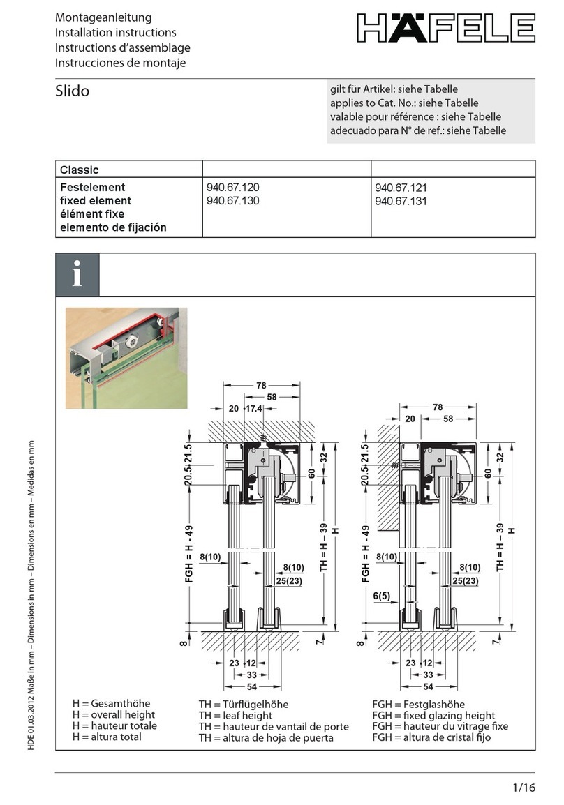
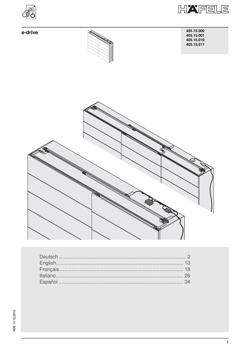
Hafele 940.41.043 Parts list manual

HDE 11.05.2010 Maße in mm – Dimensions in mm – Dimensions en mm – Medidas en mm - Misure in mm - Dimensões em mm
1/44
Montageanleitung / Betriebssanleitung
Installation instructions / Operating instructions
Instructions de montage / Instructions d'utilisation
Instrucciones de montaje/ Instrucciones de manejo
Istruzioni di montaggio / Istruzioni d'uso
Instruções de montagem/instruções de serviço
Elektrischer Schiebetürantrieb
Automation for sliding doors
Entraînement électrique de porte coulissante
Automatismo para puertas correderas
Automazione per porte scorrevoli
Automatismo eléctrico para portas de correr
gilt für Artikel:
applies to Cat. No.:
valable pour référence :
adecuado para N° de ref.:
valido per codice:
válido para o artigo:
940.41.043,
940.41.044

HDE 11.05.2010 Maße in mm – Dimensions in mm – Dimensions en mm – Medidas en mm - Misure in mm - Dimensões em mm
2/44
1
2
3
4
OPEN
69710 8 5
OPEN
Fig. 1
1000
77
115
90
67
Fig. 2
Fig. 3

3/44
HDE 11.05.2010 Maße in mm – Dimensions in mm – Dimensions en mm – Medidas en mm - Misure in mm - Dimensões em mm
1
2
3
4
OPENOPEN
Fig. 4
2000
77
115
90
67
Fig. 6
OPEN
OPEN
6 7978510
Fig. 5

HDE 11.05.2010 Maße in mm – Dimensions in mm – Dimensions en mm – Medidas en mm - Misure in mm - Dimensões em mm
4/44
40 5,5
13,5
7
Fig. 7
40
25,5
5,5
13,5
9
Ø6
Fig. 8
40
8,5
8
7
Fig. 9

5/44
HDE 11.05.2010 Maße in mm – Dimensions in mm – Dimensions en mm – Medidas en mm - Misure in mm - Dimensões em mm
40
8,5
8
25,5
9
Ø6
Fig. 10

HDE 11.05.2010 Maße in mm – Dimensions in mm – Dimensions en mm – Medidas en mm - Misure in mm - Dimensões em mm
6/44

7/44
HDE 11.05.2010 Maße in mm – Dimensions in mm – Dimensions en mm – Medidas en mm - Misure in mm - Dimensões em mm
ALLGEMEINE SICHERHEITSHINWEISE MASCHINENRICHTLINIE
Gemäß Maschinenrichtlinie (98/37/EG) ist der Installateur, der eine
Tür oder ein Tor motorisiert, den gleichen Verpflichtungen unterle -
gen wie ein Maschinenhersteller und hat somit folgendes zu tun:
- Erstellung der technischen Akte, welche die in Anlage V der
MR genannten Dokumente enthalten muß; (die technische
Akte ist aufzubewahren den nationalen Behörden minde -
stens zehn Jahre lang zur Verfügung zu halten. Diese Frist
beginnt mit dem Herstellungsdatum der motorisierten Tür);
- Aufsetzen der CE-Übereinstimmungserklärung gemäß An -
lage II-A der MR und sie dem Kunden liefern;
- Anbringung der CE-Kennzeichnung an die motorisierte Tür
laut Punkt 1.7.3. der Anlage I der MR.
HINWEISE ZUM GEBRAUCH
Betriebsklasse: 3 (mindestens 30 Zyklen täglich für 10 Jahre
oder 60 Zyklen täglich für 5 Jahre)
Gebrauch: HÄUFIG (für Mehrfamilien-Eingänge oder kleinere
Eigentumsgemeinschaften)
- Die effektiven Betriebsleistungen beziehen sich auf das
empfohlene Gewicht (2/3 des zulässigen Höchstgewichtes).
Die Verwendung mit dem zulässigen Höchstgewicht kann
die oben angegebenen Betriebsleistungen mindern.
- Die Betriebsklasse, die Betriebszeiten und die Anzahl aufein -
anderfolgender Zyklen sind Richtwerte. Sie wurden mit Hilfe
statistischer Verfahren unter normalen Betriebsbedingungen
ermittelt und können im Einzelfall abweichen. Die Werte beziehen
sich auf den Zeitraum, in dem das Produkt funktionsfähig ist,
ohne daß außerordentliche Wartungsarbeiten erforderlich sind.
-
Jede Automatikanlage weist veränderliche Faktoren auf: Reibung,
Ausgleichvorgänge sowie Umweltbedingungen können sowohl die
Lebensdauer als auch die Qualität der Funktionweise der
Automatikanlage oder einer ihrer Komponenten (wie z.B. die
Automatiksysteme) grundlegend ändern. Es ist Aufgabe des
Installationstechnikers, für die einzelne Situation entsprechende
Sicherheitskoeffizienten vorzusehen.
Diese Montageanleitungen sind ausschließlich dem
Fachpersonal vorbehalten.
Die Montage, elektrischen Anschlüsse und Einstellungen sind
unter Beachtung der praktischen Verhaltensregeln und Einhaltung
der geltenden Normen auszuführen.
Lesen Sie die Anleitungen vor der Montage des Produkts
aufmerksam durch. Eine fehlerhafte Montage kann zu ernsthaften
Verletzungen und Sachschäden führen.
Die Verpackungsmaterialien (Kunststoff, Styropor etc.) müssen
sachgemäß entsorgt werden und dürfen nicht in Kinderhände
gelangen, da sie eine Gefahrenquelle darstellen können.
Überprüfen Sie das Produkt vor der Montage auf Transportschä-
den.
Montieren Sie das Produkt nicht in explosionsfähiger Atmosphäre
oder Umgebung: Das Vorhandensein von entzündlichen Gasen
oder Dämpfen bedeutet eine große Gefahr.
Nehmen Sie vor der Montage des Antriebs alle Veränderungen an
der Struktur für die lichten Sicherheitsräume und den Schutz bzw.
die Abtrennung aller Quetsch-, Scher-, Einzieh- und allgemeiner
Gefahrenstellen.
Stellen Sie sicher, dass die vorhandene Struktur den nötigen
Anforderungen im Hinblick auf Robustheit und Stabilität entspricht.
Der Hersteller des Antriebs schließt eine Haftungsübernahme im
Falle der Nichtbeachtung der praktischen Verhaltensregeln bei der
Fertigung der zu motorisierenden Türflugel sowie von während des
Gebrauchs auftretenden Verformungen aus.
Beachten Sie bei der Montage der Schutzeinrichtungen
(Lichtschranken, Kontaktleisten, Not-Stopps etc.) unbedingt die
geltenden Normen und Richtlinien, die Kriterien der praktischen
Verhaltensregeln, die Montageumgebung, die Betriebslogik des
Systems und die von der motorisierten Tür entwickelten Kräfte.
Die Schutzeinrichtungen müssen mögliche Quetsch-, Scher-,
Einzieh- und allgemeine Gefahrenstellen der motorisierten Tür
sichern. Bringen Sie die von den geltenden Vorschriften vorgese-
henen Warn- und Hinweiszeichen zur Kennzeichnung von
Gefahrenstellen an.
Bei jeder Installation müssen die Identifikationsdaten der motori-
sierten Tür an sichtbarer Stelle angebracht werden.
Eingriffe an den elektronischen Geräten dürfen nur mit
antistatischem geerdeten Armschutz vorgenommen
werden.
Der Hersteller des Antriebs lehnt jede Haftung für die Installation
von sicherheits- und betriebstechnisch ungeeigneten Bauteilen ab.
Bei Reparaturen oder Austausch der Produkte dürfen ausschließ-
lich Original-Ersatzteile verwendet werden. Der Monteur ist
verpflichtet, dem Betreiber der Anlage alle erforderlichen Informati-
onen zum automatischen, manuellen und Notbetrieb der motori-
sierten Tür zu liefern und die Betriebsanleitung auszuhändigen.
Stellen Sie vor dem elektrischen Anschluss sicher, dass
die Angaben auf dem Datenschild mit den Werten des
Stromnetzes übereinstimmen.
Statten Sie das Versorgungsnetz mit einem allpoligen Trennschal-
ter mit Kontaktöffnungsabstand von mindestens 3 mm aus. Stellen
Sie sicher, dass der elektrischen Anlage ein geeigneter
Fehlerstrom-Schutzschalter und ein Überstromschutz vorgeschal-
tet sind.
Schließen Sie die motorisierte Tür soweit erforderlich an eine
normgerechte Erdungsanlage an.
Unterbrechen Sie während der Montage-, Wartungs- oder
Reparaturarbeiten die Stromzufuhr, bevor Sie den Deckel für den
Zugang zu den elektrischen Geräten öffnen.
DE

HDE 11.05.2010 Maße in mm – Dimensions in mm – Dimensions en mm – Medidas en mm - Misure in mm - Dimensões em mm
8/44
DE
2. VERWEIS ABBILDUNGEN
Die Funktionsgarantie und die angegebenen Leistungen werden
nur mit Zubehör und Sicherheitsvorrichtungen von HÄFELE erzielt.
2.1 Verweis auf Standard-Montage (Abb. 1-4)
[1] Antrieb
[2] Radar
[3] Bedieneinheit
[4] Die Stromversorgung an eine Wandsteckdose anschließen
2.2 Verweis auf Automatisierung (Abb. 2-5)
[5] Getriebemotor mit Schaltkreis
[6] Umlenkung
[7] Flügelanschlussbügel
[8] Riemen
[9] Türflügelsperre
[10] Funkempfänger
3. MONTAGE
Sofern nichts anderes angegeben wird, gelten alle Maße in
Millimeter (mm).
3.1 Kastenbefestigung
- Wenn nötig, die Kastenlänge (an der Umlenkung) auf das
Maß der lichten Öffnung der Tür kürzen.
Achtung: Nach dem Zuschneiden alle Komponenten wieder
korrekt im Kasten anordnen. Die Umlenkspule [6] und die Spule
des Getriebemotors [5] müssen an den Endverschlüssen liegen.
Den Riemen [8] angemessen spannen.
- Den Kasten laut Abb. 7 oder Abb. 9 -
an der oberen Führung fixieren.
3.2 Befestigung des Flügels
- Den Flügel auf Schließstellung bringen.
- Den Flügelanschlussbügel [7] so weit wie möglich der Rie-
menscheibe nähern und diese lautAbb. 7-9 am Flügel fixieren.
Achtung: Sollte die Türstärke von 40 mm abweichen, entspre-
chende Distanzstücke verwenden (nicht im Lieferumfang).
Achtung: Bei Antrieben mit zwei Flügeln müssen die Flügelan-
schlussbügel bündig zum Flügel positioniert werden (sieheAbb. 5).
- Die Tür von Hand öffnen und schließen und prüfen, ob der
Flügel korrekt gleitet.
Achtung: Den Flügel komplett öffnen und sicherstellen, dass der
Flügelanschlussbügel [7] nicht gegen die Riemenscheibe schlägt.
3.3 Befestigung Anschlagsperre
Für einen korrekten Betrieb muss der Schiebeflügel zirka 90
mm vor der vollständigen Versenkung in Öffnungsposition an-
gehalten werden.
Dann den mitgelieferten Bügel für die Anschlagsperre wie auf
Abb. 11 dargestellt befestigen.
- Der Bügel für die Anschlagsperre kann entweder innen
oder außen an der Tür befestigt werden. Die am besten
geeignete Position wählen.
- Die Tür vollständig schließen und den Bügel für die An-
schlagsperre über die vorhandenen Schlitze befestigen,
ohne die Schrauben anzuziehen.
- Die Tür bis zum Anschlag öffnen und ~90 mm sichtbar
lassen.
- Die Tür wieder vollständig schließen und den Bügel für die
Anschlagsperre mit einer dritten Schraube auf der Bohrung
ohne Schlitz dauerhaft befestigen.
3.4 Befestigung
des
Radioempfängers
Es kann ein Radioempfänger installiert werden, der eine Aktivie-
rung der Tür über eine kabellose Steuerung ermöglicht.
-
Den Radioempfänger [10] mit den mitgeliefertem Schrau-
ben im Kasten fixieren.
-
Die elektrischen Anschlüsse laut Anweisungen im entspre-
chenden Handbuch vornehmen.
-
Die Sender laut Anweisungen im entsprechenden Hand-
buch speichern.
1. TECHNISCHE DATEN
Stromversorgung 230 V~ / 50-60 Hz
Stromaufnahme 0.2 A
Spannungsversorgung Zubehör 24 V= / 0.3 A
Drücken 30 N
Geschwindigkeit beim Öffnen
beim Schließen
0.4 m/s
0.2 m/s
Einschaltdauer S2 = 30 min
S3 = 50%
Tragfähigkeit 40 kg
Abmessungen 115 x 67 x 1000 [940.41.043]
115 x 67 x 2000 [940.41.044]
Max. Verfahrweg 910 mm [940.41.043]
1860 mm [940.41.044]
Temperatur -20 °C / +55 °C
Schutzart IP20

9/44
HDE 11.05.2010 Maße in mm – Dimensions in mm – Dimensions en mm – Medidas en mm - Misure in mm - Dimensões em mm
DE
4. ELEKTRISCHE ANSCHLÜSSE
4.1 Befehle
Befehl Funktion Beschreibung
1 3 N.O. ÖFFNUNG Die Schließung des Kontakts aktiviert die Öffnung.
1 4 N.O. SCHLIEßUNG Die Schließung des Kontakts aktiviert den Schließvorgang.
1 3
1 4
N.O. STOPP Wenn gleichzeitig ein Öffnungs- und ein Schließbefehl gegeben wird,
wird das Anhalten jeglicher Bewegung ausgelöst.
Achtung: Beim erneuten Öffnung des Kontaktes nimmt das Tor wieder
die unterbrochene Bewegung auf.
41 8 N.C. UMKEHRSICHERHEIT Die Öffnung des Kontaktes löst die Umkehr der Bewegung (erneute
Öffnung) während der Schließphase aus.
4.2 Ausgänge und Zubehör
Ausgang Wert Beschreibung
1 +
0 - 24 V= / 0,3 A Stromversorgung des Zubehörs. Ausgang für Stromversorgung des
Außenzubehörs.
1 +
BL - 24 V= / 0,5 A
Sperrvorrichtung . Die Sperre wird nur bei geschlossener
Tür mit Strom versorgt.
Anm.: Bei mangelnder Stromversorgung ist die Tür entriegelt und kann
von Hand bewegt werden.
RER Radar RER. Ermöglicht denAnschluss von einer oder zwei Radareinrichtungen
RER. Achtung: Den Dip-Switch des Radars auf RER=DX stellen
4.3 Trimmer
TC Zeit der automatischen Schließung. Von 0 bis 30 s. Reguliert die Zeit, die zwischen dem
Ende des Öffnungsmanövers und dem Beginn der automatischen Schließung vergeht. Bei
geöffnetem Tor beginnt ein Öffnungsbefehl erneut mit der Zählung. Wenn man die automa-
tische Schließung ausschließen möchte, muss TC auf den Höchstwert eingestellt werden.
4.4 Anzeigen
LED (zweifarbig) Leuchtet Blinkt
Grün Stromversorgung vorhanden 24 V=. Störung Encoder / Antrieb.
Rot Sicherheit 41 - 8 geöffnet. Sicherheitstest misslungen.
4.5 Dip-Switch
Beschreibung OFF ON
DIP1 Drücken bei Schließung.
Hält den Flügel in Schließstellung.
Deaktiviert. Aktiviert.
DIP2 Wahl der Laufrichtung. Die Laufrichtung muss
berücksichtigt werden, indem man den Antrieb
von der Inspektionsseite aus betrachtet.
Öffnung nach links für Antriebe
mit einem Flügel.
WahlfürAntriebe mit zweiFlügeln.
Öffnung nach rechts für Antriebe
mit einem Flügel.
RER LED
elektromechanische Verriegelung
Schließung
Umkehrsicherheit
Öffnung
TC
0134 8 41BL
ON
12
(Spannungs-/Strom-)
Versorgung
230 V~ / 0,3 A
-
+Ausgang 24 V= / 0,3
A
Radar RER
MAX=disabled
30 s
0 s

HDE 11.05.2010 Maße in mm – Dimensions in mm – Dimensions en mm – Medidas en mm - Misure in mm - Dimensões em mm
10/44
DE
5. INBETRIEBNAHME
- Die gewünschte Öffnungsrichtung durch DIP2 wählen.
- Wenn gewünscht, das Drücken bei der Schließung durch
die Einstellung DIP1=ON aktivieren.
- TC auf den Höchstwert einstellen.
- Den Strom einschalten.
Achtung: Bei jedem Einschalten (oder Ändern des DIP2) führt
die elektrische Schalttafel ein automatisches RESET durch und
die erste Öffnungs- oder Schließbewegung erfolgt bei niedriger
Geschwindigkeit und ermöglicht die automatische Aufnahme
der Anschlagpositionen (Erfassung).
- Die korrekte Funktionsweise des Tors mit aufeinanderfol-
genden Öffnungs- und Schließbefehlen prüfen.
- Falls gewünscht, die automatische Schließung mit TC
einstellen.
- Eventuelles Zubehör anschließen und seine Funktionswei-
se prüfen.
Achtung: Bei Verwendung der Radare RER, den Dip-Switch des
Radars RER=DX einstellen.
- Sollte der Antrieb während des Schließlaufs auf ein Hin-
dernis treffen, wird dieses erfasst und das Tor öffnet sich
erneut. - Sollte der Antrieb während des Öffnungslaufs
auf ein Hindernis treffen, wird dieses erfasst und das Tor
stoppt. Wird das Hindernis zweimal hintereinander erfasst,
wird es solange als neuer Stopp betrachtet, bis es nicht
beseitigt wird.
- Der Antrieb ist mit der Funktion Push&Go ausgestattet.
Wird die Tür beim Öffnen oder Schließen von Hand ge-
drückt, schaltet sich die motorisierte Bewegung ein.
6. REGELMÄßIGE WARTUNG (alle 6 Monate)
Die Strom abschalten.
- Die Bewegungsteile (die Gleitschienen der Laufwagen)
reinigen.
- Die Riemenspannung prüfen.
- Sensoren und Lichtschranken (wenn vorhanden) reinigen.
- Die Stabilität des Automatismus kontrollieren und den
festen Sitz aller Schrauben prüfen.
- Die korrekte Fluchtung des Torflügels und die Position der
Anschläge prüfen.
Die Strom einschalten.
- Die Stabilität des Tors prüfen und ob die Bewegung glei-
chmäßig und ohne Reibungen erfolgt.
- Den korrekten Betrieb aller Befehlsfunktionen prüfen.
- Den korrekten Betrieb der Lichtschranken (wenn vorhan-
den) prüfen.
- Überprüfen, ob die von dem Tor verursachten Kräfte den
Anforderungen der geltenden Vorschriften entsprechen.
ACHTUNG: Bezüglich der Ersatzteile wird auf die Ersatzteilliste
verwiesen.
-

11/44
HDE 11.05.2010 Maße in mm – Dimensions in mm – Dimensions en mm – Medidas en mm - Misure in mm - Dimensões em mm
DE
BEDIENUNGSLEITUNG ELEKTRISCHER SCHIEBETÜRANTRIEB
ENTRIEGELUNG
Bei Betriebsstörungen oder Stromausfall das Tor von Hand
bewegen.
ALLGEMEINE SICHERHEITSHINWEISE
Diese Hinweise sind als wesenntlicher Bestandteil des Pro-
duktes dem Benutzer auszuhändigen. Sie sind sorgfältig
durchzulesen, da sie wichtige Angaben für die Sicherheit bei
Einbau, Benutzung und Instandhaltung der Anlage enthalten. Die
Hinweise sind sicher aufzubewahren und auch allen weiteren
Benutzern der Anlage zur Verfüngung zu stellen.
Das Produkt darf ausschließlich für den vom Hersteller vorge-
sehenen Verwendungszweck eingesetz werden. Jeder andere
Einsatz ist als unsachgemäß und daher gefährlich zu betra-
chten.
Der Hesteller kann nicht haftbar gemacht werden für Schäden,
die auf unsachgemäßer, fehlerhafter und zweckentfremdeter
Benutzung beruhen. Unbedingt vermeiden, sich während des
Öffnens und Schließens in der Nähe der Fernsterladen oder der
Antriebsteile aufzuhalten. Während des Öffnens und Schließens
nicht den Arbeitsbereich des elektrisch angetriebenen Fernster-
laden betreten.
Die Bewegung des elektrisch angetriebenen Fernsterladen
nicht aufhalten! Sonst Gefahrsituationen! Nicht zulassen, daß
Kinder sich im Arbeitsbereich des elektrisch angetriebenen Fer-
nsterladen aufhalten oder dort spielen. Funk-Fernsteuerungen
oder andere Steuerungen von Kindern fernhalten, damit der
Fernsterladen antrieb nicht unbeabsichtigt ausgelöst werden
kann. Bei Störungen oder Fehlbetrieb ist der Netzschalter zu
betätigen, jeder eigene Vesucht von Reparatur oder Eingrifft
zu unterlassen und ausschließlich Fachpersonal zu Rate zu
ziehen. Zuwiderhandlungen können Gefahrsituationen mit sich
bringen.
Alle Arbeiten zur Reinigung, Instandhaltung bzw. instandsetzung
sind von Fachpersonal auszuführen. Zur Sicherstellung der Lei-
stung und Betriebstüchtigkeit der Anlage sind von Fachpersonal
dier erforderlichen Wartungsarbeiten in regelmäßigen Abständen
nach Vorgabe des Herstellers durchzuführen. Insbesondere ist
auf regelmäßige Überprüfung der Betriebstüchtigkeit aller Si-
cherheitseinrichtungen zu achten. Alle Arbeiten zum Einbau, zur
Instandhaltung und Reparatur sind schriftlich zu dokumentieren
un dem Benutzer auf Anfrage zur Verfügung zu stelle.
ON
OFF
N
E
N
N
E
RTBA D
NU MED REZTUNEB NEGNIDNÄHSUA

HDE 11.05.2010 Maße in mm – Dimensions in mm – Dimensions en mm – Medidas en mm - Misure in mm - Dimensões em mm
12/44

13/44
HDE 11.05.2010 Maße in mm – Dimensions in mm – Dimensions en mm – Medidas en mm - Misure in mm - Dimensões em mm
GENERAL SAFETY PRECAUTIONS MACHINERY DIRECTIVE
Pursuant to Machine Directive (98/37/EC) the installer who mo -
torises a door or gate has the same obligations as a machine
manufacturer and shall:
- prepare technical documentation containing the documents
indicated on Schedule V of the Machine Directive;
(The technical documentation shall be kept and placed at
the disposal of competent national authorities for at least ten
years starting on the date of manufacture of the motorised
door);
- draw up the EC declaration of conformity according to Sche -
dule II-A of the Machine Directive;
- affix the CE mark on the motorised door pursuant to para.
1.7.3 of Schedule I of the Machine Directive.
OPERATING INSTRUCTIONS
Service class: 3 (minimum 30 cycles a day for 10 years or 60
cycles a day for 5 years)
Use: FREQUENT (for multi-family entrances or small condomi -
niums with frequent car or pedestrian transit)
- The operating performance specifications refer to the re -
.)thgiewdewollamumixamfo3/2tuoba(thgiewdednemmoc
Use with maximum allowed weight could reduce the above
performance specifications.
- The service class, operating times and number of conse-
cutive cycles are merely approximate. These have been
statistically determined in average conditions of use and
are not certain for each single case. They refer to the pe -
riod when the product operates without the need for special
maintenance.
- Each automatic entrance features variable factors such as:
friction, balancing and environmental conditions that can
substantially change both the duration and operating quality
of the automatic entrance or part of its components (including
automatic system). It is up to the installer to adopt adequate
safety coefficients for each single installation.
These installation instructions are intended for qualified
personnel only.
Installation, electrical connections and adjustments must be
performed in accordance with Good Working Methods and in
compliance with applicable regulations.
Before installing the product, carefully read the instructions. A poor
installation could be hazardous.
The packaging materials (plastic, polystyrene, etc.) should not be
discarded in the environment or left within reach of children, as
these are a potential source of hazard.
Before installing the product, make sure it is in perfect condition.
Do not install the product in a potentially explosive environment
and atmosphere: gas or inflammable fumes are a serious hazard
risk.
Before installing the motors, make all structural changes relating
to safety clearances and protection or segregation of all areas
where there is risk of being crushed, cut or dragged, and danger
areas in general.
Make sure the existing structure is up to standard in terms of
strength and stability. The motor manufacturer is not responsible
for failure to use Good Working Methods in building the frames to
be motorised or for any deformation occurring during use.
The safety devices (light barriers, safety edges, emergency stops,
etc.) must be installed taking into account: applicable laws and
directives, Good Working Methods, installation premises, system
operating logic and the forces developed by the motorised door or
gate.
The safety devices must protect any areas where the risk exists of
being crushed, cut or dragged, or where there are any other risks
generated by the motorised door or gate.
Apply hazard area notices required by applicable regulations.
Each installation must clearly show the identification data of the
motorised door or gate.
Before making power connections, make sure the plate
details correspond to those of the mains power supply.
Fit an omnipolar disconnection switch with a contact opening gap
of at least 3 mm.
Make sure an adequate residual current circuit breaker and
overcurrent cutout are fitted upstream of the electrical system.
When necessary, connect the motorised door or gate to a reliable
earth system made in accordance with applicable safety regulati-
ons.
During installation, maintenance and repair, interrupt the
power supply before opening the lid to access the electrical
parts.
To handle electronic parts, wear earthed antistatic
conductive bracelets.
The motor manufacturer declines all responsibility in the event of
component parts being fitted that are not compatible with the safe
and correct operation.
For repairs or replacements of products only original spare parts
must be used. The installer shall provide all information relating to
automatic, manual and emergency operation of the motorised door
or gate, and provide the user with operating instructions.
EN

HDE 11.05.2010 Maße in mm – Dimensions in mm – Dimensions en mm – Medidas en mm - Misure in mm - Dimensões em mm
14/44
2. REFERENCE TO ILLUSTRATIONS
The given operating and performance features can only be guar-
anteed with the use of HÄFELE accessories and safety devices.
2.1 Standard installation references (fig. 1-4)
[1] Actuator
[2] Radar
[3] Push-button panel
[4] Connect the power supply to a wall socket
2.2 Automation references (fig. 2-5)
[5] Gearmotor with control panel
[6] Transmission
[7] Door wing connection bracket
[8] Belt
[9] Door wing blocking device
[10] Radio receiver
3. INSTALLATION
Unless otherwise specified, all measurements are expressed
in millimetres (mm).
3.1 Case fastening
- If necessary shorten the length of the case (transmission
side) to the dimension of the door passage opening.
Attention: reposition the components correctly inside the case
after cutting. The transmission pulley [6] and the gearmotor pulley
[5] must be behind the heads. Suitably tension the belt [8].
- Fix the case to the upper guide of the door as shown in
fig. 7 or in fig. 9 .
3.2 Door wing fastening
- Place the door wing in the closure position.
- Position the door wing connection bracket [7] as close as
possible to the pulley and fix it to the door wing as shown
in fig. 7-9.
Attention: if the thickness of the door is different from 40 mm,
use suitable spacers that are not supplied.
Attention: the door wing connection brackets for double door auto-
mations must be positioned flush with the door as shown in fig. 5.
- Open and close the door to ensure that the door wing is
sliding correctly.
Attention: open the door wing completely and check that the
connection bracket [7] does not hit against the pulley.
3.3 Close stop fastening
For correct working, it is necessary to stop the sliding door wing
about 90mm before it reaches the fully opened position.
Fasten the close stop bracket (supplied) as shown in fig.11.
- The close stop bracket can be fastened on the inner or ou-
ter side of the door. Choose the most suitable position.
- Close the door completely and fasten the close stop bracket
using the slots, without tightening the screws.
- Open the door as far as the stop, leaving ~90mm within
the doorway.
- Close the door completely, tighten the screws, and perma-
nently fasten the close stop bracket using a third screw on
the non-slotted hole.
3.4 Fastening of the radio receiver
It is possible to install the radio receiver that allows the door to
be activated by means of wireless commands.
- Fasten the radio receiver [10] inside the box by means of
the supplied screws.
- Carry out the electrical connections as shown in the related
manual.
- Memorise the transmitters as shown in the related manual.
1. TECHNICAL DETAILS
Power supply 230 V~ / 50-60 Hz
Absorption 0.2 A
Accessories power supply 24 V= / 0.3 A
Thrust 30 N
Opening speed
Closing speed
0.4 m/s
0.2 m/s
Intermittence S2 = 30 min
S3 = 50%
Max load 40 kg
Dimensions
Max run
Temperature -20 °C / +55 °C
Degree of protection IP20
115 x 67 x 1000 [940.41.043]
115 x 67 x 2000 [940.41.044]
910 mm [940.41.043]
1860 mm [940.41.044]
EN

15/44
HDE 11.05.2010 Maße in mm – Dimensions in mm – Dimensions en mm – Medidas en mm - Misure in mm - Dimensões em mm
EN
4. ELECTRICAL CONNECTIONS
4.1 Commands
Command Function Description
1 3 N.O. OPENING The opening manoeuvre starts when the contact is closed.
1 4 N.O. CLOSING The closing manoeuvre starts when the contact is closed.
1 3
1 4
N.O. STOP Thecoincidenceofanopeningandclosingcommandstopsallmovements.
Attention: when the contact opens again the door proceeds with the
interrupted manoeuvre.
41 8 N.C. REVERSAL SAFETY
DEVICE
The opening of the contact during the closure manoeuvre causes the
movement to invert (re-opening).
4.2 Outputs and accessories
Output Value Description
1 +
0 - 24 V= / 0,3 A Accessories power supply.
Power supply output for external accessories.
1 +
BL - 24 V= / 0,5 A
Blocking device .
Blocking is only activated when the door is closed.
Note: the door is released in the event of power failure and can be
manually operated.
RER RER Radar. Allows the connection of one or two RER radar.
Attention: set the radar dip/switch RER=DX.
4.3 Trimmer
TC Automatic closing time. From 0 to 30 s. Adjust the time that passes between the end
of the opening manoeuvre and the start of the automatic closing manoeuvre. The count
is reset when an opening command is given with the door open. Adjust the TC to the
maximum if automatic closing is not required.
4.4 Signals
LED (two-color) ON Flashing
Green 24 V= power supply. Encoder/automation fault.
Red Safety contact 41 - 8 open. Safety test failure.
4.5 Dip-Switches
Description OFF ON
DIP1 Closure thrust.
Maintain the door wing in the closure position.
Disabled. Enabled.
DIP2 Direction selection.
The opening direction is intended by viewing the
automation from the side being examined.
Left-hand opening for single door
wing automations.
Selection for double door wing
automations.
Right-hand opening for single
door wing automations
RER
LED
Electric lock
Closing
Re-opening
Opening
TC
0134 8 41BL
ON
12
Power supply
(tension/current)
230 V~ / 0,3 A
-
+Output 24 V= / 0,3 A
Radar RER
MAX=disabled
30 s
0 s

HDE 11.05.2010 Maße in mm – Dimensions in mm – Dimensions en mm – Medidas en mm - Misure in mm - Dimensões em mm
16/44
EN
5. STARTING
- Select the desired opening direction with DIP2.
- If required, activate the closure thrust by setting DIP1=ON.
- Set TC to the maximum.
- Turn on the power.
Attention: the control panel performs an automatic RESET on each
start (or change of DIP2) and the first opening or closing manoeuvre
is performed at low speed allowing the automatic self-learning of
the stop positions (acquisition).
- Check that the door is operating correctly with subsequent
opening and closing commands.
- If required, set the automatic closing with the TC.
- Connect possible accessories and check they are functioning.
Attention: if the RER radar is used, set the radar dip-switch RER=DX.
- If the automation encounters an obstacle during closure, it is
detected and the automation opens again. If the automation
encounters an obstacle during opening, it is detected and the
automation stops. If the obstacle is detected twice in a row,
it is considered as the new stop until it is removed.
- The automation is equipped with the Push&Go function. The
motorised opening or closing operation is activated when the
door is pushed.
6. MAINTENANCE SCHEDULE (every 6 months)
Turn off the power.
- Clean the moving parts (the carriage guides).
- Check the belt tension.
- Clean sensors and photocells (if present).
- Check the stability of the automatic system and make sure
that all screws are correctly tightened.
- Check the alignment of the door wing and the stop position.
Turn on the power.
- Check the stability of the door and that the movement is
regular and without friction.
- Check that all command functions are operating correctly.
- Check that the photocells are operating correctly (if present).
- Check that the door’s developed powers are in accordance
with the present standards.
ATTENTION: For spare parts, see the spares price list.

17/44
HDE 11.05.2010 Maße in mm – Dimensions in mm – Dimensions en mm – Medidas en mm - Misure in mm - Dimensões em mm
RESUOTREVILE
D
DNAFFO
RAET
EN
OPERATING INSTRUCTION FOR SLIDING DOORS AUTOMATION
RELEASE OPERATION
In the event of malfunction or if there is no mains power supply,
move the door manually.
GENERAL SAFETY PRECAUTIONS
The following precautions are an integral and essential
part of the product and must be supplied to the user.
Read them carefully as they contain important indications for
the safe installation, use and maintenace.
These instruction must be kept and forwarded to all possible
future user of the system.
This product must be used only for that which it has been ex-
pressely designed. Any other use is to be considered improper
and therefore dangerous.
The manufacturer cannot be held responsible for possible
damage caused by improper, erroneous or unresonable use.
Avoid operating in the proximity of the hinges or moving
mechanical parts.
Do not enter the field of action of the motorised door or gate
while in motion.
Do not obstruct the motion of the motorised door or gate as this
may cause a situation of danger.
Do not lean against or hang on to the barrier when it is moving.
Do not allow children to play or stay within the field of action of
the motorised door or gate.
Keep remote control or any other control devices out of the
reach of children, in order to avoid possible involuntary activa-
tion of the motorised door or gate.
In case of breack down or malfunctioning of the product,
disconnect from mains, do not attempt to repair or intervene
directly and contact only qualified personnel.
Failure to comply with the above may create a situation of
danger.
All cleaning, maintenance or repair work must be carried out
by qualified personnel.
In order to guarantee that the system works efficiently and
correctly it is indispensable to comply with the manufacturer’s
indications thus having the periodic maintenance of the moto-
rised door or gate carried out by qualified personnel.
In particular regular checks are recommended in order to verify
that the safety devices are operating correctly.
All installation, maintenance and repair work must be docu-
mented and made available to the user.
ON
OFF

HDE 11.05.2010 Maße in mm – Dimensions in mm – Dimensions en mm – Medidas en mm - Misure in mm - Dimensões em mm
18/44

19/44
HDE 11.05.2010 Maße in mm – Dimensions in mm – Dimensions en mm – Medidas en mm - Misure in mm - Dimensões em mm
DIRECTIVE MACHINE
Selon la Directive Machine (98/37/CE) l’installateur qui “motori -
se” une porte ou un portail a les mêmes obligations du fabricant
d’une machine et donc il doit:
- prédisposer le dossier technique qui doit contenir les docu -
ments indiqués dans l’annex V de la Directive Machine.
(le dossier technique doit être gardé et tenu a dispositions
des organes de contrôle nationaux pour au moins dix ans
après la date de la fabrication de la porte motorisée);
- faire la déclaration CE de conformité selon l’annex II-A de la
Directive Machine et la remettre au client;
- afficher le marquage CE sur la porte motorisée selon le point
1.7.3.de l’annex I de la Directive Machine.
MODE D’EMPLOI
Classe de service: 3 (au moins 30 cycles par jour pendant 10
ans ou 60 cycles par jour pendant 5 ans)
Utilisation: FREQUENT (pour entrées collectives ou petite
copropriété avec passage de véhicules ou usage piéton
fréquent)
- Les performances d’utilisation font référence au poids
recommandé (environ 2/3 du poids maximum admis).
L’utilisation avec le poids maximum admis pourrait réduire
les performances susmentionnées.
- La classe de service, les temps d’utilisation et le nombre de
cycles consécutifs ont une valeur indicative. Ces données
sont relevées statistiquement dans des conditions moyennes
d’utilisation et ne peuvent être garanties pour chaque cas.
Elles font référence à la période au cours de laquelle le
produit fonctionne sans besoin d’entretien extraordinaire.
- Chaque entrée automatique présente des éléments
variables tels que: frottements, équilibrages et conditions
environnementales qui peuvent modifier considérablement la
durée et la qualité de fonctionnement de l’entrée automatique
ou d’une partie de ses composants (dont les automatismes).
Il appartient à l’installateur d’adopter les coefficients de
sécurité adaptés à chaque installation.
CONSIGNES GENERALES DE SECURITE
Le présent manuel d’installation s’adresse exclusivement
à un personnel qualifié.
L’installation, les branchements électriques et les réglages doivent
être effectués conformément à la bonne pratique et aux normes
en vigueur. Lire attentivement les instructions avant de commen-
cer l’installation du produit. Une mauvaise installation peut être
source de danger.
Ne pas jeter dans la nature les matériaux qui composent
l’emballage (plastique, polystyrène,etc.) et ne pas les laisser à la
portée des enfants car ils sont une source potentielle de danger.
Avant de commencer l’installation, vérifier l’intégrité du produit. Ne
pas installer le produit en atmosphère et environnement explosifs:
la présence de gaz ou de fumées inflammables constitue un
grave danger pour la sécurité.
Avant d’installer la motorisation, apporter toutes les modifications
structurelles relatives à la réalisation des distances minimales de
sécurité et à la protection ou séparation de toutes les zones
d’écrasement, cisaillement, entraînement et de danger en
général.
Vérifier que la structure existante est conforme aux prescriptions
de robustesse et stabilité. Le fabricant de la motorisation décline
toute responsabilité quant à l’inobservation de la bonne pratique
dans la construction des portes et portails à motoriser, et aux
déformations qui pourraient se produire au cours de l’utilisation.
Les dispositifs de sécurité (cellules photoélectriques, bourrelets
sensibles, arrêt d’urgence, etc.) doivent être installés en tenant
compte : des réglementations et directives en vigueur, des règles
de la bonne pratique, de l’environnement d’installation, de la
logique de fonctionnement du système et des forces développées
par la porte ou le portail motorisé. Les dispositifs de sécurité
doivent protéger toutes zones d’écrasement, de cisaillement,
d'entraînement et de danger en général, de la porte ou du portail
motorisé.
Appliquer les signalisations prévues par les normes en vigueur
pour signaler les zones dangereuses. L’indication des données
d’identification de la porte ou du portail motorisé doit être visible
sur chaque installation.
Avant de mettre sous tension, s’assurer que les données
figurant sur la plaque signalétique correspondent à
celles du secteur.
Prévoir sur le réseau d’alimentation un
interrupteur/sectionneur omnipolaire avec une distance
d’ouverture des contacts égale ou supérieure à 3 mm. Vérifier
la présence en amont de l’installation électrique d’un
disjoncteur différentiel et d’une protection contre la surintensi-
té adéquats.
Si nécessaire, raccorder la porte ou le portail motorisé à une
installation de mise à la terre réalisée conformément aux
prescriptions des normes de sécurité en vigueur.
Au cours des interventions d’installation, entretien et
réparation, couper l’alimentation avant d’ouvrir le couvercle
pour accéder aux parties électriques.
N’effectuer la manipulation des parties électroniques
qu’après s’être muni de bracelets conducteurs
antistatiques reliés à la terre.
Le fabricant de la motorisation décline toute responsabilité pour
la sécurité et au bon fonctionnement si des composants
incompatibles sont installés.
En cas de réparation ou de remplacement des produits, utiliser
exclusivement les pièces de rechange d'origine.
L’installateur est tenu de fournir à l'utilisateur toutes les
informations relatives au fonctionnement automatique, manuel
et d’urgence de la porte ou du portail motorisé, et remettre le
mode d’emploi à l’utilisateur de l’installation.
FR

HDE 11.05.2010 Maße in mm – Dimensions in mm – Dimensions en mm – Medidas en mm - Misure in mm - Dimensões em mm
20/44
FR
2. ELEMENTS ILLUSTRATIONS
La garantie de fonctionnement et les performances spécifiées ne
s’obtiennent qu’avec les accessoires et les dispositifs de
sécurité HÄFELE.
2.1 Références installation type (fig. 1-4)
[1] Actionneur
[2] Radar
[3] Tableau à poussoirs
[4] Raccorder l’alimentation à une prise murale
2.2 Références automatisme (fig. 2-5)
[5] Motoréducteur avec tableau électronique
[6] Renvoi
[7] Bride de fixation du vantail
[8] Courroie
[9] Dispositif de verrouillage du vantail
[10] Récepteur radiocommande
3. INSTALLATION
Toutes les mesures sont indiquées en millimétre (mm), sauf
indication contraire.
3.1 Fixation caisson
- Si cela est nécessaire il faut raccourcir la longueur du cais-
son (côté renvoi) pour qu’elle corresponde à la grandeur
de la baie de passage de la porte.
Attention : après avoir effectué cette opération remettre en place
les composants dans le caisson. La poulie de renvoi [6] et la
poulie du motoréducteur [5] doivent se trouver contre les têtes.
Tendre la courroie [8] de manière appropriée.
- Fixer le caisson au rail supérieur de la porte de la manière indiquée
sur la fig. 7 ou bien sur la fig. 9 .
3.2 Fixation vantail
- Porter le vantail en position de fermeture.
- Rapprocher la bride de fixation du vantail le plus près
possible [7] de la poulie et la fixer au vantail de la manière
indiquée sur la fig. 7-9.
Attention: si la porte a plus de 40 mm d’épaisseurs il faut utiliser des
épaisseurs appropriées qui ne font pas partie de notre fourniture.
Attention: avec l’automatisme à deux vantaux les brides de fixation du van-
tail doivent être positionnées au raz du vantail comme indiqué sur la fig. 5.
- Ouvrir et fermer manuellement la porte en contrôlant le
glissement du vantail.
Attention: ouvrir complètement le vantail et contrôler si la bride
de fixation du vantail [7] ne bute pas contre la poulie.
3.3 Fixation dispositif d’arrêt de butée
Pour obtenir un bon fonctionnement il faut arrêter le vantail cou-
lissant environ 90 mm avant qu’il ne s’encaisse complètement
en position d’ouverture.
Fixer donc la bride d’arrêt de butée fournie de la manière indi-
quée sur la fig.11.
- La bride d’arrêt de butée peut être fixée aussi bien sur le
côté interne que sur le côté externe de la porte. Choisir la
meilleure position.
- Fermer complètement la porte et fixer la bride d’arrêt de
butée avec les fentes présentes sans serrer les vis.
- Ouvrir la porte jusqu’à la butée et laisser ~90 mm pour
l’ouverture.
- Refermer complètement la porte, serrer les vis et fixer
définitivement la bride d’arrêt de butée avec une troisième
vis sur le trou sans la fente.
3.4 Fixation récepteur radiocommande
Il est possible d’installer le récepteur de la radiocommande qui
permet d’activer la porte avec des commandes sans fil de liaison.
- Fixer le récepteur de la radiocommande [10] à l’intérieur
du caisson en utilisant les vis fournies.
- Effectuer les raccordements électriques en suivant les
indications du manuel.
- Mémoriser les transmetteurs de la manière indiquée dans
le manuel correspondant.
1. DONNEES TECHNIQUES
Alimentation 230 V~ / 50-60 Hz
Absorption 0.2 A
Alimentation des accessoires 24 V= / 0.3 A
Poussée 30 N
Vitesse en ouverture
en fermeture
0.4 m/s
0.2 m/s
Intermittence S2 = 30 min
S3 = 50%
Portée maximale 40 kg
Dimensions
Course max
Temperature -20 °C / +55 °C
Degré de protection IP20
115 x 67 x 1000 [940.41.043]
115 x 67 x 2000 [940.41.044]
910 mm [940.41.043]
1860 mm [940.41.044]
This manual suits for next models
1
Table of contents
Languages:
Other Hafele Door Opening System manuals
Popular Door Opening System manuals by other brands

Cal-Royal
Cal-Royal 7760V Series installation instructions

Siemens
Siemens 3VT9300-3HG.0 operating instructions

Synergy Hardware
Synergy Hardware S300 Series Fixing instructions

Relcross Door Controls
Relcross Door Controls 4040XP.TANDEM.61.US28 installation instructions

Ackutech
Ackutech Slider s20 Assembly instructions

Craftsman
Craftsman CMXEOCG322 owner's manual