10 31-5000553 Rev.1
ENGLISH
INSTALLATIONINSTRUCTIONS
Thismanual cannot completelyillustrateall the propertiesofthe products thatwerepurchased. Please contactthelocal
Haierdistribution center ifyouhave any questionorrequest.
Installation information:
1.The distance betweenairoutlet and thegroundshould
notbe more than8.8ft(2.7m).
2.Select appropriate placesforinstallation where the
airflowcan be spreadevenlythroughout the house.
Arrangeproper locations forconnectingpipes and lines
aswell as thedrainpipeto the outdoor.
3.Ceiling construction mustbesturdy enough toholdthe
weightof the unit.
4.Make sure thattheconnecting pipe, thedrainpipe and
connectingrefrigerant lines canbeput through the
outsidewalls to connecttheoutdoor units.
5.Make the connectingpipebetween the outdoorand
indoorunits and thedrainpipeas short aspossible.
6.Please read theattachedinstallation instructions for
outdoorunit refrigerant charginginstructions.
7.The connecting flangeshouldbe checked byusers.
8. Electricalappliances such astelevision,instruments,
devices,artwork, piano, wirelessequipmentand other
valuablesshould not beplacedunder the indoorunitto
avoidpossible condensate fromdrippingonto them and
causingdamage.
The following steps can be taken after selecting the installation place:
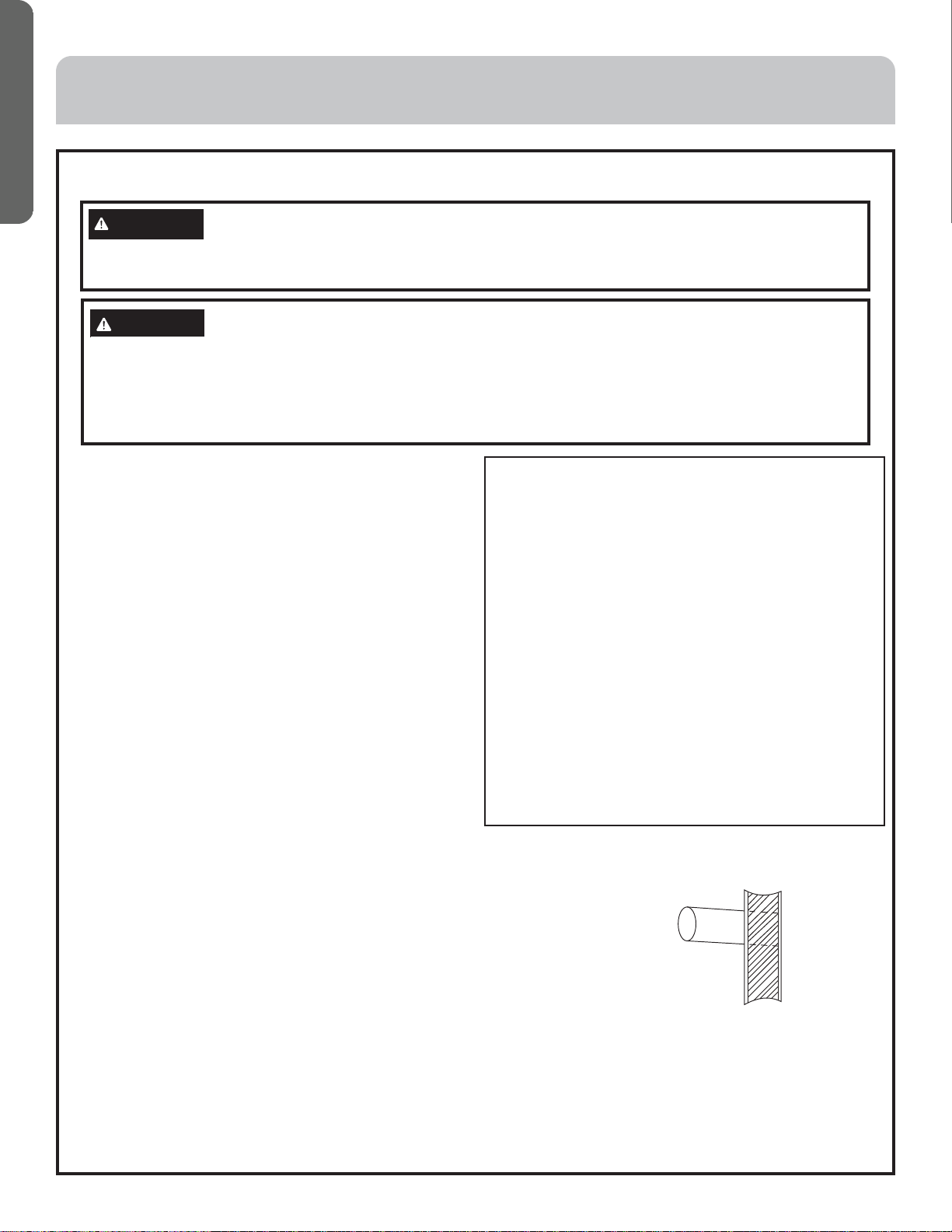
1.Cut a holeinthe wall andinsertconnection pipe andconnectingwires through afield
suppliedPVC pipe. Theholeshould be inclinedslightlydownward with aninclinationof
atleast 1/100.
2.Before cutting theopening;ensure no pipeorrebar is placedbehindthe cutting
position.Avoid cutting theopeningnear wires orconnectionpipes.
3.Hang the unitona horizontal andfirmroof. If theunitbase is notstable,it may causenoise,vibration or leakage.
4.Support the unitfirmlyand shape theconnectionpipe, connecting wiresanddrain pipe toallowthem to easilyget
throughthe opening.
WARNING
Protectthe machine fromwindsor earthquake andinstallaccording to regulations.Improperinstallation will cause
accidentsdue to unitcomingloose and falling.
CAUTION
•Choose a suitableinstallationlocation.
•Avoid places withhighsalinity (salt water)andhigh sulfur gas.Unitwill corrode anddamagewill not becovered
bywarranty.
•Avoid excess oil(includingmechanical oil) andsteam.This can reduceefficienciesand product performance.
•Avoid areas wheremachinesgenerate high frequencyelectromagneticwaves; this cancausecontrol issues.
RequiredToolsforInstallation:
•Brazingtorch
•15%silverphosphorouscopperbrazingalloy
•Wirestripper
•Soap-and-watersolutionorgasleakagedetector
•Torquewrench
•Tubingcutter
•Reamingtool
•Flaringtool
•Knife
•Measuringtape
•Level
•Vacuumpump
•Weighing-appliance
•Nitrogen
•Mini-SplitAD-87Adapter(1/4”to5/16”)
•Non-adhesiveTape
•AdhesiveTape
•Electricalwiring


 null")