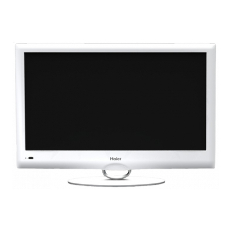
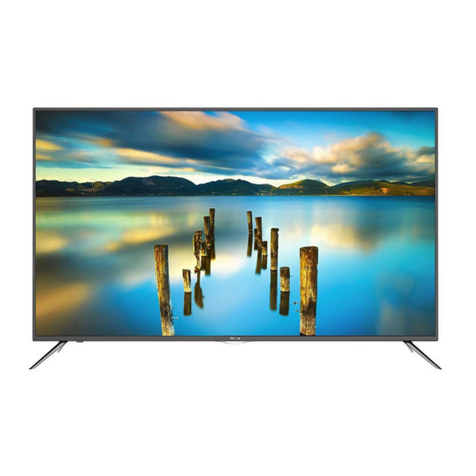
Haier LT19A1 User manual

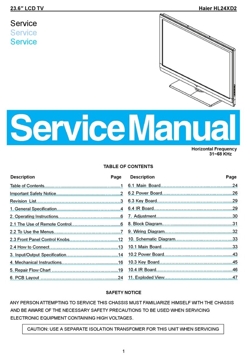
18.5″&21.6″LCDTV Haier LT19A1<22A1
1
Service
Service
Service
Horizontal Frequency
31~48KHz
TABLE OF CONTENTS
Description Page Description Page
SAFETY NOTICE
ANY PERSON ATTEMPTING TO SERVICE THIS CHASSIS MUST FAMILIARIZE HIMSELF WITH THE CHASSIS
AND BE AWARE OF THE NECESSARY SAFETY PRECAUTIONS TO BE USED WHEN SERVICING
ELECTRONIC EQUIPMENT CONTAINING HIGH VOLTAGES.
CAUTION: USE A SEPARATE ISOLATION TRANSFOMER FOR THIS UNIT WHEN SERVICING
6.2 Power Board…..…………..………….…..…….......36
6.3 Key Board………………………..……..……….......39
6.4 IR Board…………………………..……….…….......39
7.Adjustment..............................................................40
8.Block Diagram.…….................................................41
9.Wiring Diagram.……...............................................42
10.Schematic Diagram………..……..………………...43
10.1 Main Board…………….…………………...….......43
10.2 Power Board………..…....…………...……….......59
10.3 Key Board……………….………….………….......61
10.4 IR Board……………………………….……….......62
11.Exploded View……………………….………….…...63
12.BOM List……………….…………………………….65
Table of Contents.......……....................................…........1
Important Safety Notice.......................................……......2
Revision List…………………………………………………3
1. General Specification.................................………........4
2. Operating Instructions…………………….……...….......6
2.1 The Use of Remote Control…….…………...…….......6
2.2 To Use the Menus…...………………….….………......7
2.3 How to Connect…….…………………….…..…….....16
2.4 Front Panel Control Knobs……………….………......23
3. Input/Output Specification…………....................…....25
4. Mechanical Instructions…………………….................28
5. Repair Flow Chart ……………………….…….…….....30
6. PCB Layout ………………..………………....…..........34
6.1 Main Board………………..……………...…….….......34

2
Important Safety Notice
Proper service and repair is important to the safe, reliable operation of all Haier Company Equipment. The service
procedures recommended by Haier and described in this service manual are effective methods of performing
service operations. Some of these service operations require the use of tools specially designed for the purpose.
The special tools should be used when and as recommended.
It is important to note that this manual contains various CAUTIONS and NOTICES which should be carefully read in
order to minimize the risk of personal injury to service personnel. The possibility exists that improper service
methods may damage the equipment. It is also important to understand that these CAUTIONS and NOTICES ARE
NOT EXHAUSTIVE. Haier could not possibly know, evaluate and advise the service trade of all conceivable ways in
which service might be done or of the possible hazardous consequences of each way. Consequently, Haier has not
undertaken any such broad evaluation. Accordingly, a servicer who uses a service procedure or tool which is not
recommended by Haier must first satisfy himself thoroughly that neither his safety nor the safe operation of the
equipment will be jeopardized by the service method selected.
Hereafter throughout this manual, Haier Company will be referred to as Haier.
WARNING
Use of substitute replacement parts, which do not have the same, specified safety characteristics might create
shock, fire, or other hazards.
Under no circumstances should the original design be modified or altered without written permission from Haier.
Haier assumes no liability, express or implied, arising out of any unauthorized modification of design.
Servicer assumes all liability.
FOR PRODUCTS CONTAINING LASER:
DANGER-Invisible laser radiations when open AVOID DIRECT EXPOSURE TO BEAM.
CAUTION-Use of controls or adjustments or performance of procedures other than those specified herein may
result in hazardous radiation exposure.
CAUTION -The use of optical instruments with this product will increase eye hazard.
TO ENSURE THE CONTINUED RELIABILITY OF THIS PRODUCT, USE ONLY ORIGINAL MANUFACTURER'S
REPLACEMENT PARTS, WHICH ARE LISTED WITH THEIR PART NUMBERS IN THE PARTS LIST SECTION OF
THIS SERVICE MANUAL.
Take care during handling the LCD module with backlight unit
-Must mount the module using mounting holes arranged in four corners.
-Do not press on the panel, edge of the frame strongly or electric shock as this will result in damage to the screen.
-Do not scratch or press on the panel with any sharp objects, such as pencil or pen as this may result in damage to
the panel.
-Protect the module from the ESD as it may damage the electronic circuit (C-MOS).
-Make certain that treatment person’s body is grounded through wristband.
-Do not leave the module in high temperature and in areas of high humidity for a long time.
-Avoid contact with water as it may a short circuit within the module.
-If the surface of panel becomes dirty, please wipe it off with a soft material. (Cleaning with a dirty or rough cloth may
damage the panel.)

3
Revision List
Version Release Date Revision
Instructions Customer Model Model
LT19A1 E19AM2NB3WH72N
A00 Jan.25,2010 Initial release
LT22A1 E22AG2NB3WH72N

4
1. General Specification
* This model complies with the specifications listed below.
* Designs and specifications are subject to change without notice.
* These models may not be compatible with features and/or specifications that may be added in the future.
Model No. LT19A1 LT22A1 LT26A1 LT32A1 LT42A1
DISPLAY
Viewable 18.5” 22” 26” 32” 42”
Television
System PAL, SECAM standard, DVB-T standard
CONNECTIONS
Tuner input (75Ω) PC IN: D-SUB and PC Audio (Headphone mini-jack)
Recommended:1360x768/60Hz
Component Video and L/R Audio input
Supported resolution: 480i, 576i/p, 720p, 1080i, 1080p(42" only)
HDMI input
Supported scan rates: 480p, 480i, 576p, 576i, 720p, 1080i, 1080p(42" only)
SCART 1
SPDIF
HDMI 1
SCART 1
SPDIF
HDMI 1
SCART 1
SCART 2
SPDIF
HDMI 1
HDMI 2
SCART 1
SCART 2
SPDIF
HDMI 1
HDMI 2
SCART 1
SCART 2
SPDIF
HDMI 1
HDMI 2
HDMI 3
SCART 1: RGB + CVBS in/out + audio in/out
Rear
Connectors
SCART 2: S-Video + CVBS in/out + audio in/out
COMMON INTERFACE
AV In (Composite Audio/ Video)
Side
Connectors
Earphone Output
WEIGHT & DIMENSIOIN
455x145x388 528x382x175.8 657.2x489.3x219.0 789.5x569.1x239.5 1015.4x703.0x280.5
Dimensions
with Stand
(W x H x D) mm mm mm mm mm
Weight with
Stand 3.7kg 4.8kg 8.0kg 11.1kg 20.5kg
Weight
without
Stand and
Base
3.45kg 4.55kg 6.8kg 9.3kg 17.6kg

5
WALL MOUNTING
VESA-compatible wall
bracket (W x H) 100x100 mm 100x100 mm 200x100 mm 200x200 mm 400x200 mm
Screw type Metric 4x10
mm
Metric 4x10
mm
Metric 4x10
mm
Metric 6x10
mm
Metric 6x10
mm
POWER
Power Consumption 50W 55W 120W 130W 200W
Standby < 1W
Mains Power AC100-240V~,
50/60Hz
AC100-240V~,
50/60Hz
AC220-240V~,
50/60Hz
AC220-240V~,
50/60Hz
AC220-240V~,
50/60Hz
Audio Power 3W + 3W 3W + 3W 5W + 5W 5W + 5W 10W + 10W
Ambient Temperature 5°C - 35°C
PACKAGE CONTENTS
Supplied Accessories
TV unit x1
Power cord x 1
Remote control x1 (with two size AAA alkaline batteries)
User manual x1
Setup Guide x1

6
2. Operating Instructions
2.1 The Use of Remote Control
POWER
Press to turn ON/OFF(standby) the
TV.
SOURCE
Press repeatedly to choose the
various input sources.
Number buttons
Press to enter TV channel number to
select channel.
EPG
Press to display the Electronic
Programme Guide.
PRE CH
Press to display the previous
channel.
HDMI
Press to choose HDMI source mode.
YPbPr
Press to choose YPbPr source mode.
VIDEO
Press to choose AV source mode.
PC
Press to choose PC source mode.
VOL+ / VOL-
Press + or - to adjust the volume.
CH Λ/ CH V
Press Λor V to browse through the
TV channels.
MUTE
Switch the sound ON/OFF.
TELETEXT
Press to display or close the Teletext.
MIX
Display the Teletext with TV.
SIZE
Press to change the font size: Full
screen, Top half and Bottom half.
SUBPAGE
Display the sub page (when
available).
INDEX
Press to return to page 100 or the
index page.
SUBTITLE
• In TV mode: It works only for turning
on the subtitle and change to the next
page marked as subtitle.
IT t d Sl tth t
ZOOM
Select the display aspect from Auto,
Normal (4:3), Wide (16:9), subtitle,
full screen, or 14:9 mode.
DUAL
Press to select from mono, stereo,
Dual I, or Dual II.
AUDIO ADJ
Press to choose from Personal,
Speech, Music.
VIDEO ADJ
Press to choose the Smart Picture
mode from Personal, Standard,
Movie, Vivid, Eco.
SLEEP
Press to set the preset time to switch
the TV to standby mode
automatically.
MENU/EXIT
Press to open or close menu.
▲, ▼, ◄, ►, OK
Press to adjust or confirm the various
function items on the menu.
INFO
Press to display or close the
information screen.
Colour buttons
• In TV mode: Follow the directions in
the OSD screen.
• In Text mode: Text control buttons.
HOLD
Press to stop the scrolling of pages.
The text decoder stops receiving
data.
REVEAL
Reveal hidden information such as
answers to a quiz.
FAV
Display the Favourite Channel List.
CH-LIST
Display the Channel List.
USB
Press USB to display the multimedia
selection screen.
FREEZE

7
2.2 To Use the Menus
1. Press the MENU/EXIT button to display or close the main menu
2. Use the Navigation Ring to move around to select, adjust or confirm an item in the OSD (On Screen Display)
menu.
Press the MENU/EXIT button to enter the main OSD. Adjust the items including Picture, Sound, TV, Features, and
Parental.
However, some function items in the menus may only be enabled in the particular source modes.
PICTURE MENU
The Picture menu in most source modes shows as below. It provides several video adjustment items for user fine
tuning the video display.
1. Smart Picture: To set the best picture appearance to a predefined picture setting from Standard, Vivid, Movie,
Eco, or Personal.
2. Brightness: To brighten the dark parts of the picture.
3. Contrast: To sharpen the picture quality.
4. Colour: To add or reduce colour.
5. Tint: To adjust the picture tint.
6. Sharpness: To improve detail.
7. Colour Temperature: To choose between Normal (neutral), Warm (redder), and Cool (bluer).
8. Advanced Control:
[Noise Reduction] - To filter out and reduces the image noise and improve picture quality. Select the effect degrees
from Off, Low, Medium, High, or Auto.
[Flash Tone] - To adjust the skin colour to be more natural.
[Back Light] - To make the background colour brighter or darker.
[DCR] - Dynamic Contrast Ratio (DCR) auto adjusts the brightness of the screen to show more depths in the darker
areas.
[HDMI Mode] - (HDMI only) User can select Auto/graphic/Video mode.
Description as following:
• Auto: Automatic to get device information, device will indicate sending timing is video timing or graphic timing (PC
timing).
• Graphic: Force video timing shows as graphic timing, for example: 720p shows 1280x720@60Hz; 1080i shows
1920x1080@60Hz. This mode optimizes for PC input.
• Video: Force graphic timing shows as video timing, for example:
1280x720@60Hz shows 720p;
1920x1080@60Hz shows 1080i.
This mode optimises for DVD player, camcorder, and other video appliances inputs.

8
SOUND MENU
The Sound menu provides audio adjustment for user to modify the audio setting.
1. Sound Mode: To set the TV to a predefined sound setting from Personal, Music, or Speech.
2. Balance: To adjust the balance between left and right channels.
3. Virtual Surround: To add greater depth and dimension to the TV sound.
4. Digital Audio Out: To select the Digital Audio Out from Off or PCM.
5. SPDIF Delay: SPDIF Delay function will affect SCART/Line out audio also delay at that time. The Nor Dig HD IRD
shall support the possibility to adjust the audio delay on the SPDIF output (if available) up to 250 ms and it should be
adjustable in 10ms steps, as the IRD may have several different user set-ups, resulting in different a/v delays; e.g.
the IRD may be connected to several types of external audio amplifiers and the STB may be connected to several
types of external screens.
6. AVL: Choose On or Off to adjust volume to be consistent across programmes and channels automatically.
The following functions are only available for digital channels with audio signals.
7. Type: This function enables you to choose the type of the additional narration during the TV watching from
Normal, Hard of Hearing, or Audio Description.
Hard of Hearing: This function provides narration to deaf and hard of hearing viewers.
8. Audio description: When the Type is set to “Audio Description”, you can adjust the volume of the audio
description.

9
TV MENU
1. Country: To select the relevant country.
This is the country you are in, or the country whose channels you want to receive if you live near its borders.
2. Audio Carrier (ATV only): Select Stereo, Dual 1, Dual 2, or Mono for ATV channel.
3. 1st and 2nd Audio: Use this function when two or more audio languages are broadcast. This is the language to
be used for digital channels if it is available.
4. Channels: Enter the channels submenu, and choose from Channel Scan, Update Scan, Single RF Scan, Analog
Manual Scan, Channel Skip, Channel Sort, Channel Edit, Decoder, and Analog CH Fine Tune.
[Channel scan] - Channel Scan will retune the television automatically. It is recommended to run the Channel Scan
periodically to ensure that all new services are added.
[Update scan] - Search the new channels automatically that are not in the channel list.
[Single RF Scan (Digital Only)] - Enter the Single RF Scan in the Channels submenu to scan digital channels.
[Analog Manual Scan] - The television can be tuned-in manually using Analog Manual Scan. Use the number keys

10
to enter the Start Frequency to scan up or scan down.
[Channel skip] - To prevent certain programs from being viewed by pressing CH + / - buttons on the remote control,
the program position can be skipped.
Tip: The skipped program may not be found by pressing CH + / - buttons but can be access by pressing number
buttons directly.
Tip: The skipped program may not be found by pressing CH Λ/ V but can be accessed by pressing number
buttons directly.
[Channel sort] - Change the order of the Channel List.
[Channel Edit] - Enter the Channel Edit in the channels submenu to edit the channel number and channel name by
using the number buttons 0~9.
Note: The following RC number-mapping table will not be shown on the TV screen.
[Decoder (Analog only)] – Channel Decode support the Canal+ (paid television channel); however, the channel
also
broadcast some un-encrypted programs.
These programs without encryption can be viewed free of charge.
[Analog CH Fine Tune] - Select Analog CH Fine Tune in the Channels submenu to adjust the frequency.
FEATURES MENU
The Features menu in TV mode shows as below. This menu gives users the most flexibilities to satisfy their
generally demands. According to the various requirements in different source modes, certain features should be
hidden (disable) on the menu. The details footnotes will be described clearly below.

11
1. Menu Language: To select the on-screen display menu language.
2. Picture Format: To select the available display format from Auto, Normal, Native (HDMI only), Zoom 1, Zoom2,
or Wide.
3. Time:
[Time Zone] - To select the time zone you are in.
[Time] - To set the time and date or select auto synchronization.
Tip: Before you want to set the time and date by your own, please make sure Auto synchronization is Off.
[Sleep Timer] - To set the TV to turn itself off within a certain time.
4. Subtitle:
[Analog Subtitle] - To display the transmitted subtitle on the screen. Either this text can be permanently displayed
(assuming that the service is available in the broadcast) or only when mute is active.
[Digital Subtitle] - Use the Digital Subtitle function when two or more subtitle languages are broadcasted. If subtitle
data in a selected language is not broadcasted, the default language subtitle will be displayed.
[Subtitle Type] - To choose the subtitle type from normal or hearing impaired.
5. Teletext Language:
[Digital Teletext Language] - To select the teletext language.
[Decode Page Language] - To set the teletext language to the regional location.
6. Common Interface: This menu appears with your CI supplier information.
7. HDMI Scan Info (HDMI only):
[Automatic] - Set to underscan or overscan automatically when the video signal is detected.
[Underscan] - When the video signal is detected, all active pixels and lines are displayed with or without border.
[Overscan] - When the video signal is detected, some active pixels and lines at the edges are not displayed.
8. Reset Default: To reset all TV settings to the original factory values.
PARENTAL MENU
Enable you to control special functions for the TV channels.
1. Channel Block: To block certain TV channels.

12
2. Parental Guidance: To control access programs based on their age ratings. All settings apply to digital channels.
Note: This function operates according to information from the broadcasting station. Therefore if the signal has no
information, this function does not operate.
3. Input Block: To disable the specific external input signals.
4. Set Password: To set or change your password. Please follow the instructions to set it. All number combinations
from 0000 to 9999 are valid.
Tip: Remember that 5351 is the default Change Password code. If your access code has been changed or you have
forgotten the code, you can always get in by inputting the default code.
5. Clear All: To clear all the settings in the parental submenu.
COMMON INTERFACE MODULE
The Common Interface CI Slot, is designed to accept the Conditional Access CA Module coupled with a Smart card,
in order to view pay TV programmes and additional services. Contact your Common Interface service provider for
further information about modules and subscription options. Please note that CA modules and smart cards are not
included, or supplied as optional extras by us.
WARNING: Switch off your TV before any module is inserted into the Common Interface slot.
1. Correctly insert the CA Module and then the Smart Card into the CI slot located at the side of the TV.
2. Turn on the TV and press MENU and select the TV submenu. “Common interface” will be displayed if the CA
module is detected. Wait for few moments until the card is activated.

13
3. Select Common Interface to view the menu options and information on the inserted CI card.
4. Press OK to access the card menu, for more details refer to the module’s instruction manual.

14
5. When module is removed, the “Common Interface” menu will disappear from the screen.
OAD OPERATION
OAD for Software Update function:
1. When you get the updating news from the TV shop’s web, you can update the operation software using the
Download
menu. The data for various units are transferred consecutively on a special receiving channel.
2. You need to search the channel with updating code stream. (Note: you can get information from the TV shop or
internet.)
Operation
1. When you search the channel. You will get a information.
2. Press ▲▼to confirm if you would like to “Accept” this new software or “Reject“ and use ►button to action
update new software.

15
3. After the programming, please use to confirm if you would like to restart the TV.
The software will be updated completely after restart the TV.
NOTE: You must not switch off the unit during this process!

16
2.3 How to Connect
Coaxial (RF)
Using Your Antenna or Digital Cable for DTV.
1. Turn off the HDTV.
2. Connect the coaxial (RF) connector from your antenna or digital cable (out-of-thewall, not from the Cable Box) to
the TV ANTENNA connector.
3. Turn on the HDTV.
4. Select ATV/DTV using the SOURCE button on the remote control or the control key on the side of the TV.
Using Your Antenna or Cable for DTV.
1. Turn off the HDTV.
2. Connect the coaxial (RF) connector from your antenna or cable (out-of-the-wall, not from the Cable Box) to the TV
ANTENNA connector at the rear of the HDTV
3. Turn on the HDTV.
4. Select ATV/DTV using the SOURCE button on the remote control or the control key on the side of the TV.
Using the Antenna or Cable for your VCR
1. Turn off the HDTV and VCR.
2. Connect the “Output to TV”, “RF Out” or “Antenna Out” connector on the rear of your VCR to the TV ANTENNA

17
connector at the rear of the HDTV.
3. Turn on the HDTV and VCR.
4. Select ATV/DTV using the SOURCE button on the remote control or the control key on the side of the TV.
NOTE: If you have an off-air antenna or cable TV, connect it to the “Antenna In” connector on the rear of your VCR.
Connecting Your HDTV Set-Top Box
Using HDMI (19”/22” only have one HDMI)
HDTV Set-Top Boxes that have a HDMI digital interface should be connected to the HDMI input of the LCD HDTV
for optimal results.
Connecting your HDTV Set-Top Box (Best)
1. Turn off the HDTV and HDTV Set-Top Box.
2. Connect a HDMI cable to the HDMI output of your HDTV Set-Top Box and the other end to the HDMI Input at the
rear of the HDTV.
3. Turn on the HDTV and HDTV Set-Top Box.
4. Select HDMI using the SOURCE button on the remote, side of the HDTV, or directly by pressing the HDMI button
on the Remote Control.
NOTE: The HDMI input on the HDTV supports High-bandwidth Digital Content Protection (HDCP). HDCP encrypts
the transmission between the video source and the digital display for added security and protection.
Refer to your HDTV Set-Top Box user manual for more information about the video output requirements of the
product or consult your cable or satellite operator.
For HDTV Set-Top Boxes with DVI
1. Turn off the HDTV and HDTV Set-Top Box.
2. Using a HDMI-DVI cable, connect the DVI end to your HDTV Set-Top Box and the HDMI end to the HDMI Input at
the rear of the HDTV.
3. Turn on the HDTV and HDTV Set-Top Box.
4. Select HDMI using the SOURCE button on the remote, side of the HDTV, or directly by pressing the HDMI button
on the Remote Control.
NOTE: The HDMI input on the HDTV supports High-bandwidth Digital Content Protection (HDCP). HDCP encrypts
the transmission between the video source and the digital display for added security and protection.
Refer to your HDTV Set-Top Box user manual for more information about the video output requirements of the
product
or consult your cable or satellite operator.
The DVI to HDMI connection provides video only. Connection to an alternate audio player is required for audio.

18
Using Component Video
Connecting your HDTV Set-Top Box (Better):
1. Turn off the HDTV and HDTV Set-Top Box.
2. Connect the Pr (red colour) connector on your HDTV Set-Top Box to the corresponding Pr (red colour) connector
in the Component group.
3. Connect the Pb (blue colour) connector on your HDTV Set-Top Box to the corresponding Pb (blue colour)
connector in the Component group.
4. Connect the Y (green colour) connector on your HDTV Set-Top Box to the corresponding Y (green colour)
connector in the Component group.
5. Using an audio cable (red and white connectors), connect the cable to the audio output connectors associated
with the Component output on your HDTV Set-Top Box and connect the other end to the audio connectors
associated with the Component.
6. Turn on the HDTV and HDTV Set-Top Box.
7. Select YPbPr using the SOURCE button on the remote, side of the HDTV or directly by pressing the YPbPr button
on the Remote Control.
NOTE: Refer to your HDTV Set-Top Box user manual for more information about the video output requirements of
the product or consult your cable or satellite operator.
Connecting Your Basic Set-Top Box
Using Composite Video
1. Turn off the HDTV and Set-Top Box.
2. Using an AV Cable, connect the Video (yellow colour) connector on your Set-Top Box to the corresponding Video
(yellow colour) connector in the AV group at the side of the HDTV.
3. Using the red and white connectors, connect the cable to the audio output connectors associated with the Video
output on your Set-Top Box and connect the other end to the audio connectors associated with the AV input at the
side of the HDTV.
4. Turn on the HDTV and Set-Top Box.
5. Select AV using the SOURCE button on the remote, side of the HDTV or directly by pressing the VIDEO button on
the Remote Control.

19
Using Coax (RF)
1. Turn off the HDTV and Set-Top Box.
2. Using a Coax (RF) cable, connect one end to the TV OUT (RF) on your Set Top Box and the other end to the TV
input at the rear of the HDTV.
3. Turn on the HDTV and Set-Top Box.
4. Select ATV/DTV using the SOURCE button on the remote control or the control key on the side of the TV.
NOTE: Refer to your Set Top Box user manual for more information about selecting the video or RF output of the
product.
Connecting Your DVD Player
Using HDMI
DVD players that have a digital interface such as HDMI (High Definition Multimedia Interface) should be connected
to the HDMI input of the LCD HDTV for optimal results.
Connecting your DVD Player (Best)
1. Turn off the HDTV and DVD player.
2. Connect a HDMI cable to the HDMI output of your DVD player and the other end to the HDMI Input at the rear of
the HDTV.
3. Turn on the HDTV and DVD player.
4. Select HDMI using the SOURCE button on the remote, side of the HDTV or directly by pressing the HDMI button
on the Remote Control.
For DVD Players with DVI:
1. Turn off the HDTV and DVD player.
2. Using a HDMI-DVI cable, connect the DVI end to your DVD player and the HDMI end to the HDMI Input at the
rear of the HDTV.
3. Turn on the HDTV and your DVD player.
4. Select HDMI using the SOURCE button on the remote, side of the HDTV, or directly by pressing the HDMI button
on the Remote Control.
NOTE: Refer to your DVD player user manual for more information about the video output requirements of the

20
product.
The DVI to HDMI connection provides video only. Connection to an alternate audio player is required for audio
output.
Using Component Video
Connecting your DVD Player (Better)
1. Turn off the HDTV and DVD player.
2. Connect the Pr (red colour) connector on your DVD player to the corresponding Pr (red colour) connector in the
Component at the rear of the HDTV.
3. Connect the Pb (blue colour) connector on your DVD player to the corresponding Pb (blue colour) connector in
the Component group at the rear of the HDTV.
4. Connect the Y (green colour) connector on your DVD player to the corresponding Y (green colour) connector in
the Component group at the rear of the HDTV.
5. Using an audio cable (red and white connectors), connect the cable to the audio output connectors associated
with
the Component output on your DVD player and connect the other end to the audio connectors associated with the
Component input at the rear of the HDTV.
6. Turn on the HDTV and DVD player.
7. Select YPbPr using the SOURCE button on the remote, side of the HDTV or directly by pressing the YPbPr button
on the Remote Control.
NOTE: Refer to your DVD player user manual for more information about the video output requirements of the
product.
Using SCART
Connecting your DVD Player (Good):
1. Turn off the HDTV and DVD player.
2. Connect the SCART socket of your DVD player to the SCART socket of the HDTV.
3. Turn on the HDTV and DVD player.
4. Select AV using the SOURCE button on the remote, side of the HDTV, or directly by pressing the VIDEO button
on the Remote Control.
Other manuals for LT19A1
1
This manual suits for next models
1
Table of contents
Other Haier LCD TV manuals

Haier
Haier L19C1120 User manual

Haier
Haier HL26K User manual

Haier
Haier LT32F6 User manual

Haier
Haier LT19M1CWA User manual

Haier
Haier L32A8A-A1 User manual

Haier
Haier HL26K1 - K-Series - 26" LCD TV User manual

Haier
Haier L32M3F User manual

Haier
Haier LE32K700 User manual

Haier
Haier HL37XLE2 User manual

Haier
Haier L22B1120 Assembly instructions