Hailo Professional HS 8 User manual

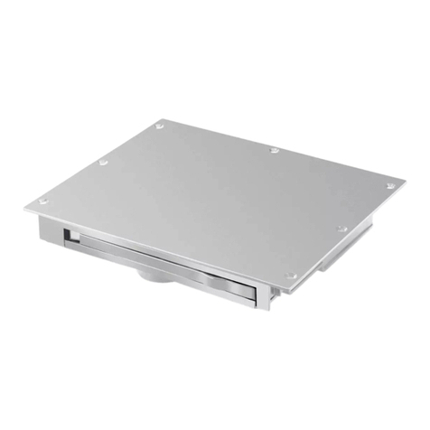
Shaft cover, flush, loads as per EN124 (Class B+D)
(This view is for illustration purposes only and, depending on the equipment,
is not necessarily representative of the Hailo scope of delivery).
Chapter 01: Mounting dimensions Page 02
Chapter 02: Mounting / setting the cover in concrete Page 04
Chapter 03: Adjusting the hinges Page 05
Chapter 04: Installing the opening aids (gas-pressurised springs, LA36 or hydraulic unit) Page 06
Chapter 05: Installing the safety barriers (grille or guard rail) Page 09
Chapter 06: Using the shaft cover Page 10
Chapter 07: Maintenance and servicing information Page 16
Assembly and User Instructions
Hailo Type HS8 Shaft Cover
Status: 10-2021 Page 1 of 16

Surface - Raised pattern safety plate:
Chapter 01: Mounting dimensions
The surrounding concrete edge required is derived from the customer’s statics
calculation and formwork and reinforcement plans. This is not a constituent part
of these assembly instructions.
As a guideline, we recommend the following minimum thicknesses on all sides
as a supplement to the external dimensions of the shaft cover indicated below:
For stationary traffic (e.g. car park): 80mm
For flowing traffic (carriageway): 120mm
These dimensions must be observed at the rear, including behind the hinge
boxes!
Minimum quality of concrete: C35/45, allowing for the customer’s
specifications!
The cover must be set in
concrete to the full height of
240 mm.
The locking or hinge side
must run in the direction of
travel.
For the optional add-on to the
raised pattern safety plate cover,
with the option: “Hydraulic opening
using internal cordless screwdriver
actuator”, the following dimensions
must be considered when designing
the concrete surround:
clear depth +296 mm
clear width +205 mm
clear width
clear depth
clear width
clear width +205 mm
clear depth
(clear depth)+296mm
Status: 10-2021 Page 2 of 16

Surface - Trough for filling with concrete, asphalt or paving:
Chapter 01: Mounting dimensions
The cover must be set in
concrete to a height of 240
mm. The top 50 mm allows
for paving or other
carriageway coverings to be
laid.
The locking or hinge side
must run in the direction of
travel.
For the optional add-on to the cover
with trough, with the option:
“Hydraulic opening using internal
cordless screwdriver actuator”, the
following dimensions must be
considered when designing the
concrete surround:
clear depth +414 mm
Paving finish:
Empty trough and no reinforcement on
the hinge boxes
Concrete finish:
Reinforcement in the lid and on the hinge
boxes
Execution asphalt:
retaining plates in the lid
Execution
asphalt
clear width +215 mm
clear width
clear width +215 mm
clear depth
Status: 10-2021 Page 3 of 16

Chapter 02: Mounting / setting the cover in concrete
IMPORTANT!!!
To avoid damage to the cover, it is absolutely essential to comply with the following
instructions. Hailo accepts no liability or warranty for damage caused by improper
handling. The lid must sit correctly in the frame when creating the outer concrete
surround, and must be firmly screwed to the frame! Otherwise there is a risk that the
frame will move when the reinforcement is installed or when set into concrete. The
correct and secure positioning of the lid may then no longer be guaranteed.
1. The necessary openings in your structure derive from the customer’s statics
calculation and the formwork and reinforcement plans for the required concrete
surround. (Guide values, page 2+3)
2. Remove the parts supplied from the cover, e.g. the operator key or the gas-
pressurised springs. A level contact surface must be created for the shaft cover before
the cover is inserted into the opening in the structure. The depth of the contact surface,
measured from the top ground surface, depends on the design height of the cover.
The contact surface can be adjusted to the slope of the ground, but
no diagonal distortion of the cover must be caused.
3. Using appropriate lifting tackle or equipment, such as a crane, forklift, digger, etc.,
insert the shaft cover into the opening provided. The cover must only be introduced in a
closed and firmly-screwed condition. There are hooks at the corners into which ropes
or chains can be inserted.
4. Execute the horizontal alignment in accordance with the eventual carriageway.
For alignment, the frame can be shimmed on all sides.
5. Once the cover is finally fixed, seal the gap all the way round between frame and
structure (wooden framework, sealing strip, etc.).
6. Use the operator key to check whether the lid is firmly screwed to the frame. To
safeguard against lifting and movement when concreting, the cover may be secured
using ballast.
7. Insert the reinforcement around the cover into the opening provided for it, and
fasten the reinforcement to the masonry anchors of the shaft cover.
8. The cover can now be finish-poured. It is recommended that the concrete is rammed
with internal vibrocompactors. Allow for the setting times specified for the concrete.
9. After the concrete has set, the cover can be opened for the first time and the gas-
pressurised springs fitted and adjusted in accordance with the instructions.
10. Once all works have been completed, it is important to remove any concrete
residues and dirt from the frame and the lid. This ensures that your Hailo shaft cover
will have a long and trouble-free service life.
Status: 10-2021 Page 4 of 16

Chapter 03: Adjusting the hinges
If the position or the seating of the lid on the frame has moved, this can be rectified as
follows:
1.) Open the lid.
2.) Mark the current position of the hinge brackets on the lid.
3.) Loosen the screw-fastening of the hinge brackets, initially just on
one side, and slide the lid approx. 1-2 mm in the direction respectively
required.
If the lid needs e.g. to sit further back towards the hinge box when closed,
with the lid opened it needs to be lowered slightly. Then re-tighten the
screws firmly (the lid can be moved/lowered using a standard crowbar).
4.) Repeat the steps described in point 3.) on all further hinges.
5.) Close the lid.
Screws
Status: 10-2021 Page 5 of 16

Opening aid - Gas-pressurised springs:
Chapter 04: Assembling the opening aids
The gas-pressurised springs can be adjusted for force by fitting an adjustable stop.
1. First, screw the piston rod head to the frame at the bottom using the pre-fitted screw.
Only tighten the nut to a point where the screw can still be rotated!
2. Next, install the cylinder head as shown; when the lid is moved, the screw slides in
the slot, so do not tighten this nut firmly either.
3. By fixing the stop / sleeve at a variable height, it is possible to adjust the point to
which the gas-pressurised spring also slides up when opening the lid.
If the shaft cover has only one gas-pressurised spring, the point is to be chosen such
that the lid stops when opened at around 80°. It is then easy to move the lid manually
into the latch locking position. On lids with a depth of 600 mm, the stop is not
required.
If multiple gas-pressurised springs are used, it is sensible to fit the stops in such a way
that the gas-pressurised springs are used in succession. The advantage of this is that,
when opening, the lid does not open too quickly and, when closing, there is no need to
push immediately against the force of all the gas-pressurised springs. The further the
stop is moved downwards, the greater the force of the gas-pressurised springs when
opening starts.
Please note: Do not move the stop so far downwards that the piston of the gas-
pressurised spring comes into contact with the base of the cylinder!
Variable in height
Status: 10-2021 Page 6 of 16

Opening aid - Electric actuator LA36:
Chapter 04: Assembling the opening aids
The LA36 electric actuator is equipped with internal limit switches that switch off
the actuator in the stop positions. Accordingly, there are no special
requirements for limit switch polling even on the control side.
1. First, the e-controller (available from Hailo as an option) should be fitted into
the space provided, and the wiring to the cover put in place.
2. Next, the mounting bracket with the pre-mounted nuts and washers is
screwed to the frame on the hinge side.
The bracket must be self-supporting to the back against the concrete!
3. The actuator is attached to the frame bracket with the motor side (as shown
in the images below) at the bottom, using the screw, nut and anti-removal bolt.
Tighten the nut only to the point where the anti-removal bolt does not stick
against the frame bracket!
4. Next, use the e-controller to extend the actuator fully until it reaches the stop
position, so that the piston rod can be installed at the attachment point of the lid
(using the screw, nut and spacer tubes).
Only tighten the nut to a point where the screw can still be rotated!
Note: Covers equipped with an LA36 actuator may have additional gas-
pressurised springs, depending on the size. These are needed for even opening
and as protection against overloading the actuator in the event of heavy lid
weights.
The gas-pressurised springs are installed as described on page 5.
excavation protection
Status: 10-2021 Page 7 of 16

Filling with oil:
Opening aid - Internal hydraulic cordless screwdriver unit
Chapter 04: Assembling the opening aids
The internal hydraulic cordless screwdriver unit is partly pre-assembled and
supplied together with the cover. The unit assembly remains to be filled using
the oil supplied (see illustration bottom left), and the cylinder and connecting
hoses may also need to be installed on site.
1. First, the mounting bracket with the pre-mounted nuts and washers is screwed
to the frame on the hinge side.
The bracket must be self-supporting to the back against the concrete!
2. The cylinder is attached at the bottom to the frame bracket and to the
attachment point on the lid (using screws, nuts and spacer tubes).
Only tighten the nuts to a point where the screws can still be rotated!
3. Attach hose1 as shown in the illustration below to the cylinder and quick-
release unit, and hose 2 to the cylinder and hydraulic unit connection.
4. Next, the pump must be rotated in a clockwise direction or operated using a
cordless screwdriver until the cylinder has filled completely with oil and the air
has escaped from the system.
Note: Covers equipped with internal hydraulics may have additional hydraulic
cylinders or gas-pressurised springs, depending on the size. These are needed
for even opening and as protection against overloading the hydraulic system in
the event of heavy lid weights.
The gas-pressurised springs are installed as described on page 5.
Please also note the chapter on use when installing the shaft cover!
Tube 1
Tube 2
Connection unit
Connection
unit
Loosen screws
Status: 10-2021 Page 8 of 16

Safety barrier - Safety grille
Chapter 05: Mounting the safety barriers
The safety grilles are supplied pre-installed with the cover. For retrofitting, please follow the
instructions below. The safety grilles come in two versions:
1. Folding to the rear - Grille installed directly onto the hinge side of the frame
Locking provided by chain on the grille, to be suspended from the hook on the lid.
2. Folding to the side - Installation on mounting tracks on the hinge side and locking side of
the frame. The grilles are inserted into these tracks. When opened they stand up on their
own and they can be removed at any time.
1. Loosen the screw
connection of the gas
2. Insert the grille and screw it to the connection points. Do
not tighten, screw must still be able to turn.
1. When retrofitting this type of grid, bolt
anchors must be set first. To do this, hold the
rails in the correct position and mark the
holes. Then mount the rails on the frame.
2. Insert grid
Status: 10-2021 Page 9 of 16

Safety barrier - Integrated fold-out guard rails
Chapter 05: Mounting the safety barriers
No. 1
No. 2
No. 3
Labelling
using stickers
Example: Guard rail folded into cover
The guard rail parts and attaching brackets are supplied unassembled in order to avoid
damage during transport and concreting in. After the construction works are completed, the
shaft cover can be opened and the elements of the guard rail fitted. There are threaded
bolts in the frame with pre-assembled washers and nuts, to which the attaching brackets and
the guard rail elements are fitted. The elements of the guard rail are identified based on
their position using stickers.
Status: 10-2021 Page 10 of 16

Opening and closing the shaft cover
Chapter 06: Using the shaft cover
To use the HS8 shaft cover, you need an operator key # 9515031 and, if used, the key to the
profile cylinder used for locking (optional).
1. Use the operator key to release the upper brass three-sided screw bolt(s) of the locks and
store them somewhere clean (figure 1).
2. Use the key to unlock and remove the lock assembly, if any.
3. Release the bottom brass three-sided screw bolt(s) (figures 2 and 3).
4. Use the key hook to reach into the opening on the neck of the lock and lift the lid (figure 4).
5. The gas-pressurised springs assist opening up to around 80°; beyond that you must open the
lid further by hand until the latch locks into position (figure 5).
Figure 1
Figure 2
Figure 3
Figure 4
Figure 5
Latch
Status: 10-2021 Page 11 of 16

Opening and closing the shaft cover
; beyond that you must open the
Chapter 06: Using the shaft cover
Emergency release (optional equipment):
To operate the emergency release from inside the structure (from below), the
activating lever must be pulled downwards. This disables the locking mechanism
function, and the lid can then be opened / or pushed upwards.
To close the cover, the locking bracket must be reinserted into the guide and the
lever moved back into its original position.
Opening the shaft cover from outside the structure (from above) is performed as
described on the previous page.
Attention! - We advise that a combination of emergency release and safety
barriers such as safety grilles or guard rails is not sensible. After operating the
emergency release, it may potentially not be possible, or only possible with great
difficulty, for a fleeing person to open or push up the lid if this is obstructed by a
grille or a folded-up guard rail sitting in the frame.
Status: 10-2021 Page 12 of 16

Opening and closing the shaft cover - Electric actuator LA36
Chapter 06: Using the shaft cover
Hailo e-controller for LA 36 (optional):
Attention! - When opening or closing the cover, please first ensure that no other persons are
located in the immediate hazard area.
1. First release the locks using the operator key, as described on page 11.
2. Release the emergency off switch on the e-controller - the controller is now ready to operate.
3. To open the cover, press and hold the “Up / Open” button - the cover now opens for as long
as the button is kept pressed, and switches off automatically when it reaches the end position. If
the button is released before then, the lid immediately stops moving.
4. To close the cover, press and hold the “Shut / Close” button - the cover likewise only moves
as long as the button is kept pressed and stops moving immediately the button is released, and
at the latest in the end position.
The lid latch must be released before the cover can be closed.
5. When leaving the cover, the emergency off switch must be locked again in order to prevent
inadvertent activation of the cover. Screw the locks in again correctly. This is important to ensure
that the seal is pressed firmly against the frame and a watertight surface water seal is formed.
Emergency opening:
The lower attachment point of the LA36 actuator on the frame is designed in such a way that,
when the shaft cover is in the closed position, the lid can be opened or raised easily e.g. using a
crane, as it is only in this position that the anti-removal bolt clears the attachment point. The
anti-removal bolt locks the attachment point immediately after an opening operation is started
using the LA36 actuator, with the result that the actuator cannot unintentionally slip out of the
frame bracket.
excavation protection
Status: 10-2021 Page 13 of 16

Opening and closing the shaft cover - Internal hydraulic cordless screwdriver unit
the cover now opens for as long
inadvertent activation of the cover. Screw the locks in again correctly. This is important to ensure
when the shaft cover is in the closed position, the lid can be opened or raised easily e.g. using a
Chapter 06: Using the shaft cover
Attention! - When opening or closing the cover, please first ensure that no other
persons are located in the immediate hazard area.
1. First release the locks using the operator key, as described on page 11.
Then loosen the cover screws, using the hydraulic unit.
2. Opening: Covers with internal hydraulics are supplied with a special operator key.
This has a long size 12 socket at one end. This end of the key can be used to operate
the outlet valve on the hydraulic unit. First check whether the valve is closed by placing
the operator key onto the valve’s mounting cone and turning it carefully in a clockwise
direction. (If the valve is not closed, the pump simply feeds the oil back into the reservoir
and the lid does not open.)
The pump is powered by a cordless screwdriver and a four-sided 1/4” extender from a
standard socket wrench set. For this, the cordless screwdriver must be set to clockwise
(rotating in a clockwise direction) and placed onto the mounting cone of the pump. The
different gear settings on the cordless screwdriver then influence the opening speed of
the lid. Shortly before the end, before the lid is fully open, the cordless screwdriver
should be operated at a slower speed.
4. Closing: When the operator key is placed onto the mounting cone of the outlet valve
and turned in an anti-clockwise direction, the valve opens and the shaft cover lid closes
under its own weight. Please operate the outlet valve carefully to familiarise yourself with
this procedure and thus with the closing speed of the lid.
The lid latch must be released before the cover can be closed.
5. After closing the lid, please screw the locks in again correctly.
This is important to ensure that the seal is pressed firmly against the frame and a
watertight surface water seal is formed.
Note:
The hydraulic unit is fitted with an internal pressure limiter and is pre-set to a system
pressure of max. 180 bar. This maximum pressure must not be changed or increased
under any circumstances, otherwise the hydraulic components may be damaged.
Through the possible use of additional gas-pressurised springs, the shaft covers are
designed in such a way that the cover can be opened or closed using this system
pressure. The hydraulic hoses are designed by the manufacturer for a max. pressure of
350 bar. Despite this, it is important to check the hoses for possible damage, cracks,
porous points etc. every time the cover is operated or opened. Defective hoses or other
components are to be replaced immediately in order to ensure the safe use of the
system.
Emergency opening:
If the internal hydraulic unit should fail to operate correctly, for emergency opening from
the outside it is possible to connect a hand-pump (#9559731) or a portable hydraulic
unit with a cordless screwdriver actuator (#9559881) via a quick-release unit.
Status: 10-2021 Page 14 of 16

Opening and closing the shaft cover - Internal hydraulic cordless screwdriver unit
1. To prevent or exclude "corrosion" or cold welding of the screwed connection between lid
and frame, the three
2. The screw bolts can be greased on the thread so that they can be freed more easily if the
shaft cover has not been opened for a prolonged period.
3. The seal must always be kept clean in order to avoid damage and the resulting loss of
sealing.
4. For that reason, clean the seal around the frame and the stainless steel contact surfaces
between the lid and the frame with a hand
The use of stainless steel removes the need to apply oil or grease.
This ensures that your Hailo shaft cover will have a long and trouble
Chapter 06: Using the shaft cover
Valve
Cone hexagon 12mm
Pump
Cone square 1/4"
Hydraulic unit
cover caps
Emergency opening
Connection for hand pump
or mobile hydraulic unit
Status: 10-2021 Page 15 of 16

1. To prevent or exclude "corrosion" or cold welding of the screwed connection between lid
and frame, the three-sided screw bolts are made of brass.
2. The screw bolts can be greased on the thread so that they can be freed more easily if the
shaft cover has not been opened for a prolonged period.
3. The seal must always be kept clean in order to avoid damage and the resulting loss of
sealing.
4. For that reason, clean the seal around the frame and the stainless steel contact surfaces
between the lid and the frame with a hand-brush or cloth every time before using the lid.
The use of stainless steel removes the need to apply oil or grease.
This ensures that your Hailo shaft cover will have a long and trouble-free service life.
Chapter 07: Maintenance and servicing information
9586271 - GB
Status: 10-2021 Page 16 of 16
Other manuals for Professional HS 8
1
Table of contents
Other Hailo Door Opening System manuals
Popular Door Opening System manuals by other brands

Briton
Briton 121 Installation

Norton
Norton CloserPlus CLP7570 Series installation instructions

FAAC
FAAC SDK WIRELESS quick start guide

Dormakaba
Dormakaba TS 93 B EN 2-5 Mounting instructions

Nice
Nice spido SP6000 Instructions and warnings for the fitter

Assa Abloy
Assa Abloy NORTON RIXSON 5200 Series installation instructions