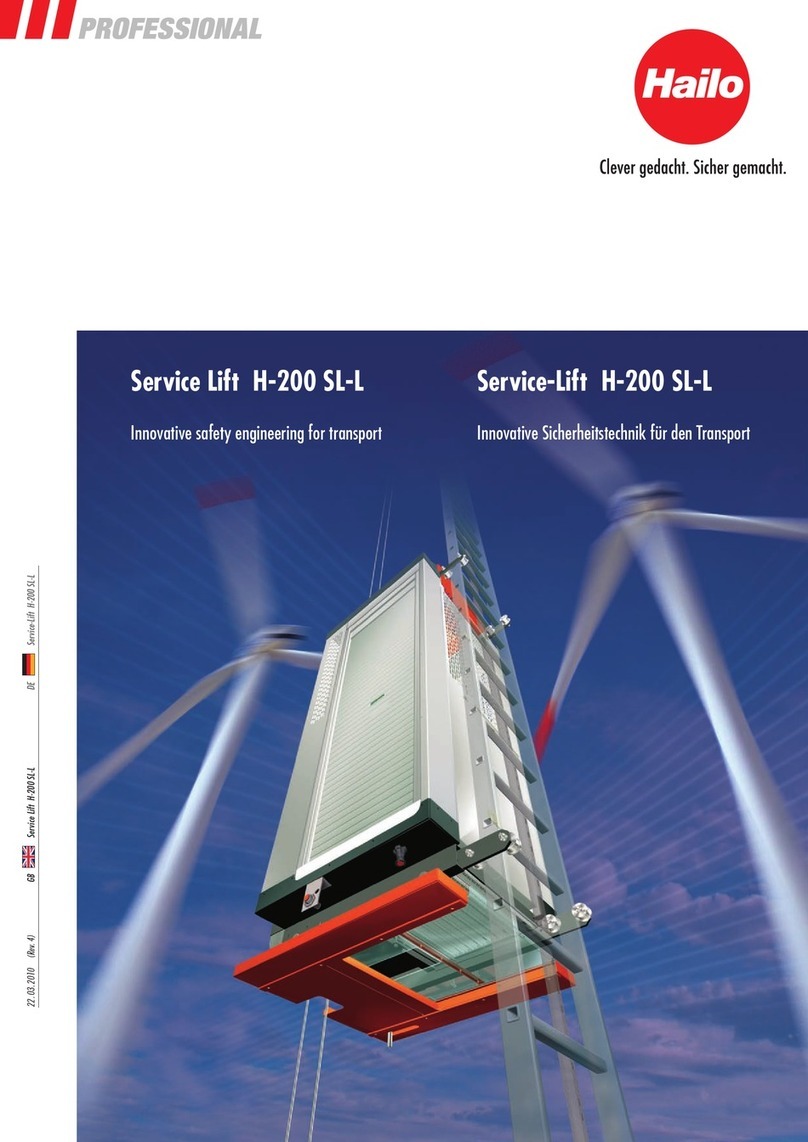
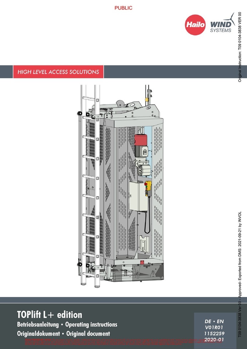
Hailo TOPlift CCV User manual

Read the instructions prior to performing any task!
Supplement to the operating instructions. Valid only in connection with the orig-
inal operating instructions.
Hailo TOPlift CCV

© Hailo Wind Systems - Without prior written approval by Hailo, no part of this publication may be reproduced in any way, transmitted, transcribed, stored in a
storage medium, or translated into any language or computer language. Copyright infringement can also affect Hailo's product support for this device. Hailo reserves
the right, without prior notice, to make changes to this manual and the product it describes. The content of this manual does not include any contractual or other
obligations by Hailo and is not legally binding. This publication was prepared with great care. However, if you find errors or wish to make suggestions for improve-
ment, please write to Hailo. The original language of this document is German. If desired, you can request a written copy.

Table of contents
1 Preface..................................................................................................................... 4
2Introduction.............................................................................................................. 6
3 Safety....................................................................................................................... 7
4 Operation................................................................................................................. 9
5 Maintenance........................................................................................................... 11
Table of contents
• TOPlift CCV • 3

1 Preface
Dear customer,
Thank you for choosing our product.
The Hailo TOPlift CCV is an enhanced version of the Hailo TOPlift L.
The CCV (cold climate version) enables operation of the service lift to temperatures as low as
-35°C.
This manual describes the distinctive features and enhancements of the Hailo TOPLift CCV and is
valid only together with the original operating instructions of the Hailo TOPlift L.
You will find the operating instructions in the service lift.
Read the operating instructions!
Observe the notices regarding safety. Follow all applicable safety and operating
instructions.
Always keep this supplement together with the operating instructions in the service lift.
The end user must ensure the product is handled correctly through the fol-
lowing:
–
Correct operation by trained personnel
–
Maintenance and inspection of the service lift at the prescribed intervals
–
Creation of an emergency plan
Machine described: Hailo TOPlift CCV
Language: EN Addition to the original operating instructions
(supplement to a complete machine)
Revision:
Number, date, revision Initial generation 01, 2013-10
We at Hailo Wind Systems wish you every success in your work!
This manual is valid only in connection with the original operating instructions.
You will find the operating instructions in the service lift.
The manufacturer's warranty for all components is two years, provided that the technical docu-
mentation is observed.
Adhere to the stipulated schedules for periodic tests and inspections.
Warranty
Schedules
Preface
• TOPlift CCV • 4

NOTICE!
The end user shall be liable for any damages arising from non-adherence to
these schedules.
Testing the safety equipment:
nTests and maintenance must be performed according to the specifications of the manufac-
turer.
Mechanical components must be checked for proper functioning, as well as for wear or
damage, and replaced if necessary.
nA non-scheduled test is required if components of the service lift are overloaded through
improper use.
Preface
• TOPlift CCV • 5

2 Introduction
The Hailo TOPlift CCV is an enhanced version of the Hailo TOPlift L.
The service lift is equipped with additional functions and components. These are described below.
The Hailo TOPlift CCV can be operated at temperatures as low as -35°C.
To ensure proper functioning at especially low temperatures, the following components are addi-
tionally or alternatively installed in the service lift:
nTemperature measurement in the arrester device
nHeating mat on the back of the arrester device
nTemperature measurement in the switch cabinet
nSwitch cabinet heater
nLock mechanism of shutter door (modified switch type)
The service lift can only be operated if the components in the switch cabinet
and the arrester device have reached their respective operating temperature.
Supplemental information to the operating instructions
This document is valid only together with the original operating instructions.
General instructions
Introduction
• TOPlift CCV • 6

3 Safety
For safe operation of the service lift to -35°C, the following safety devices and safety features
are required. Only with faultlessly functioning components and features can safety be guaran-
teed.
Should you have any questions, please feel free to contact us at Hailo Wind Systems.
The switch cabinet is equipped with its own heater. This ensures that the components in the switch
cabinet also function reliably at lower temperatures. The temperature in the switch cabinet must
lie above -15°C, otherwise the controls are not enabled and the service lift is not operational.
The switch cabinet heater raises the temperature up to +10°C and then automatically shuts off.
The switch cabinet heater is constantly in operation at temperatures below +10°C. The heater
remains activated even with the main switch turned off.
DANGER!
Danger of electrical shock!
The switch cabinet heater is also activated with the main switch turned off.
Many areas of the control unit continue to carry voltage even with the main
switch turned off. Never perform work on the control unit if it is under voltage.
Switch the voltage supply to the service lift off if necessary.
A temperature sensor is located in the switch cabinet. If the temperature in the switch cabinet lies
under -15°C, the controls are not enabled and the service lift cannot be operated.
The arrester device is equipped with a heating mat [1] on the back of the casing. An insulating
mat is adhered to this. When necessary, the heating mat heats up the arrester device to the
operating temperature.
Installed in the arrester device is a temperature sensor, which forwards the temperature to the
control unit. As long as the temperature in the arrester device is below -15°C, the controls are
not enabled and the lift cannot be moved.
CAUTION!
The arrester device is equipped with a heating mat. Do not remove the insula-
tion on the back of the arrester device: The surface of the heating mat can
reach a temperature of 60°C!
Safety instructions
Switch cabinet heater
Temperature measurement in the switch cabinet
Heater of the arrester device
Temperature measurement of arrester device
Safety
• TOPlift CCV • 7

On the front of the switch cabinet [1] are two indicator lights. When the red indicator light is lit,
the service lift is in a heating-up phase, in other words, the operating temperature of the arrester
device and/or the control unit has not yet been reached. In this case, the service lift cannot be
operated.
After the operating temperature has been reached, the red indicator light goes out and the green
indicator light signals that the temperature in the switch cabinet and in the arrester device lies
above the threshold level and the lift is now operational.
The Hailo TOPlift CCV is equipped with a special shutter door lock [1]. This safety device prevents
the shutter door from opening during ascent or descent as well as when stopped between plat-
forms (to avoid danger of falling). It is only possible to enter and exit when the cabin stops
precisely in the intended position level with the platform.
A magnet is installed on the platform. The service lift is equipped with a solenoid switch which
stops the lift at the intended position and unlocks the shutter door. In an emergency, the shutter
door can also be unlocked manually to enable exiting of the service lift.
Temperature measurement indicator lights
Lock mechanism of shutter door
Safety
• TOPlift CCV • 8

4 Operation
Before commencing travel, the following must be observed in addition to the points given under
Chapter 4.3 of the original operating instructions: The service lift can only be used if the oper-
ating temperatures of the arrester device and control unit lie within the specified range. This is
indicated by the lights on the front of the control unit [1].
If the red indicator light is lit, the service lift is in the heating-up phase and the lift cannot be
used. In this case, wait until the red light has gone out and the green light is lit.
Heating up time
If the components of the arrester device and the control unit are not at oper-
ating temperature, the service lift cannot be used.
In this case, wait until the red light has gone out and the green light is lit. The
heating up time lasts about 15 minutes
WARNING!
Temperature settings
Never change the temperature settings on the controls! The proper functioning
of safety-related components will otherwise be jeopardised!
You can find the correct settings for the temperature controls in the circuit dia-
gram.
Releasing the shutter door (escape release) from inside or outside:
In the event of repairs or a dangerous situation, the emergency release / escape release makes
it possible to open the shutter door by manual activation of a switch [1] located in the entry sill
of the shutter door. The switch can be activated from inside or outside through an opening in the
frame of the entry sill.
1. In an emergency, press the pushbutton on the switch. This disables the locking of the
shutter door.
2. The shutter door can now be opened.
3. The emergency release must be reset in order to restore the equipment to operational
status. To do this, pull the button back out to its starting position.
Readiness for operation
Disabling the shutter door lock
Operation
• TOPlift CCV • 9

CAUTION!
When you open the shutter door, you may fall out!
Therefore make sure, before opening the shutter door, that all persons in the
cabin are secured to one of the two attachment points in the cabin ceiling with
a connecting device (component of the personal protective equipment (PPE) to
prevent falls).
DANGER!
Caution, danger of falling!
If you are not secured with your personal protective equipment, you could fall!
Always secure yourself in a suitable manner against falls by employing your
personal protective equipment (PPE).
Operation
• TOPlift CCV • 10

5 Maintenance
DANGER!
Danger during maintenance work
There is a risk of injury when performing maintenance work.
– Before beginning any maintenance work, switch the machine main switch
in the control cabinet to the lowest position and secure it with a padlock to
prevent it being restarted.
WARNING!
Risk of severe bodily injury
Tools laid on top of the machine or left behind within it can be hurled through
the air or fall inside the machine, causing severe injuries and damage.
– Check that no tools or other objects have been forgotten in or on the
machine before restarting it.
NOTICE!
Observe the instructions in the chapter
CAUTION!
Maintenance measures
Adequate tools and workshop equipment are essential for carrying out mainte-
nance tasks.
– Only technically faultless, suitable and in some cases only prescribed tools
may be used (e.g. for opening maintenance doors).
The inspection (and maintenance) requires that the entire travel path be travelled. The structure
should therefore, prior to beginning the maintenance work, be placed in an operating state
which allows climbing of the tower.
nMaintenance work may only be carried out by the following personnel:
– Authorised Hailo employees
– Authorised employees of your local Hailo service center
– Authorised employees of your company who have been suitably trained and certified
by Hailo (qualified persons)
nA scheduled inspection of the drive components must be performed annually.
nA scheduled inspection and maintenance of the service lift must be performed at intervals
of one or two years.
nScheduled maintenance of the drive components is required every 4 years or after 200
hours of operation.
nNon-scheduled inspection and maintenance is required if the service lift or other compo-
nents of the system are damaged through improper use. Such non-scheduled inspection or
maintenance is particularly indicated after a collision or impact.
nThe system components must be cleaned, greased (oiled) or exchanged as necessary.
Safety instructions and general information
Maintenance
• TOPlift CCV • 11

Use the cleaning and lubricating agents which have been approved by the manufacturer of
the system.
The result of the inspection and maintenance must be documented in the inspection and mainte-
nance report.
Abnormalities, defects or other noticed problems are to be listed in the respective inspection and
maintenance report with the name of the component.
DANGER!
Danger of fatal electrical shock!
Contact with voltage-conducting components of the machine poses a danger of
death due to electrical shock.
– Only specially trained, qualified personnel are allowed to perform work
on the electrical circuitry of the machine.
– For all work on the machine’s electrical circuitry, turn off the main switch
and secure it with a padlock against being switched on again.
DANGER!
Caution, danger of falling!
If you are not secured with your personal protective equipment, you could fall!
– Always secure yourself in a suitable manner against falls by employing
your personal protective equipment (PPE).
WARNING!
Maintenance work!
For maintenance and repair work performed on the electrical system, the entire
machine must be switched free of current on the lowest level by means of the
main switch on the switch cabinet or with the main switch in the cabin.
The main switch on the switch cabinet (and in the cabin, if applicable) are
secured with a padlock.
Electrician
Electricians have the professional training which enables them to perform work on electrical
installations.
Qualified person
A qualified person is someone who, due to their professional training and experience, current
professional activities as well as completion of a separate manufacturer training, has the neces-
sary specialist expertise to inspect equipment and who has been authorised and certified by the
manufacturer.
Procedures for inspection and maintenance
nCheck the closure force of the screw connections for all system components by random sam-
pling.
If a loose screw connection is found on a system component, all connection screws on this
component must be tightened or, if needed, replaced.
nCheck rollers and roller bearings on the system components for sluggishness and damage.
Damaged or worn bearings must be replaced.
Maintenance
• TOPlift CCV • 12

nThe welded joints on the floor grate should be visually checked. If cracks are detected, the
components must be replaced.
nCheck the mechanical and electrical function of all system components and inspect them for
damage and corrosion.
If any defects are detected, the system component must be repaired or replaced.
Interval Maintenance work Personnel
yearly Visual check of all screw connections Qualified person
Check of all screw connections for correct torque Qualified person
The correct torques are listed on page 73 of the original operating instructions.
DANGER!
Danger of electrical shock!
The switch cabinet heater is also activated with the main switch turned off.
Many areas of the control unit continue to carry voltage even with the main
switch turned off. Never perform work on the control unit if it is under voltage.
Switch off the voltage supply to the service lift in the wind energy installation if
necessary.
Interval Maintenance work Personnel
Every 2 years Functional test of the switch cabinet heater Electrician
Functional test of the heater of the arrester device Electrician
Check of the red and green indicator lights on the front of the switch cabinet Electrician
Check and, if necessary, adjustment of the correct temperature default according to the circuit diagram. Electrician
Functioning of the shutter door lock Qualified person
Additional “Cabin” inspection and maintenance plan
Additional “Switch cabinet” inspection and maintenance
plan
Maintenance
• TOPlift CCV • 13


1, 1, en_GB • Subject to technical changes! Art.-Nummer 1147609
Table of contents
Other Hailo Lifting System manuals
Popular Lifting System manuals by other brands

Anthony Liftgates
Anthony Liftgates ETU-20-44 Operation manual

Smiley Lifting Solutions
Smiley Lifting Solutions URW706 quick start guide

Sealey
Sealey MPSD1 instructions

Caldwell
Caldwell OMNI DRIVE installation instructions

Shoremaster
Shoremaster 1264 Instructions and Safety Tips

Vestil
Vestil CART-600-S-HR instruction manual