2. SPECIFICATIONS
3. WARNINGS, CAUTIONS AND NOTES
2
*1
Temperature sensor (191-212) can only be used to measure temperatures below 500
°
C (932
°
F).
To measure higher temperatures, use an applicable temperature probe.
*4 If the sensor burns out, the burn-out will be indicated. Once the indication occurs, replace
the sensor with new one.
The specifications may be subject to change without notice.
*2 is blinking: The batteries are low. Prepare new batteries.
*3
will be always shown: The battery is depleted and must be replaced.
1℃
0 - 700℃*1
K (CA) type thermocouple
±3°C (between 300 and 600°C)
±5°C (Other than above)
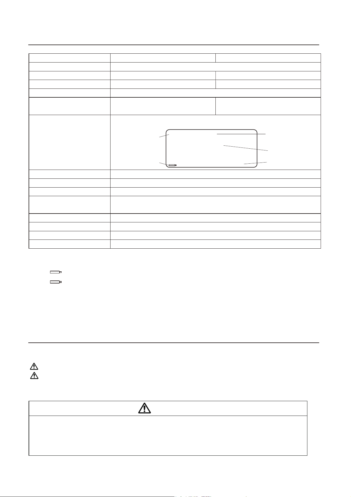
Besides measured temperatures, display indications include the following:
AA sized (LR6) battery × 6 (alkaline cell recommended)
193 (W) × 90 (H) × 219 (D) mm (w/o barcode reader)
0.93 kg (w/o batteries, bar code reader)
2 m
1.1 m
A-miniB
0 to 40℃, max.80% RH, without condensation
Applicable rated pollution degree 2 (According to IEC/UL61010-1)
1℉
32 - 1,300℉*1
±6°F (between 572 and 1,112°F)
±10°F (Other than above)
Celsius type Fahrenheit type
Burnout alarm*4
Battery
status*2, 3 MAX HOLD
Measurement
Mode
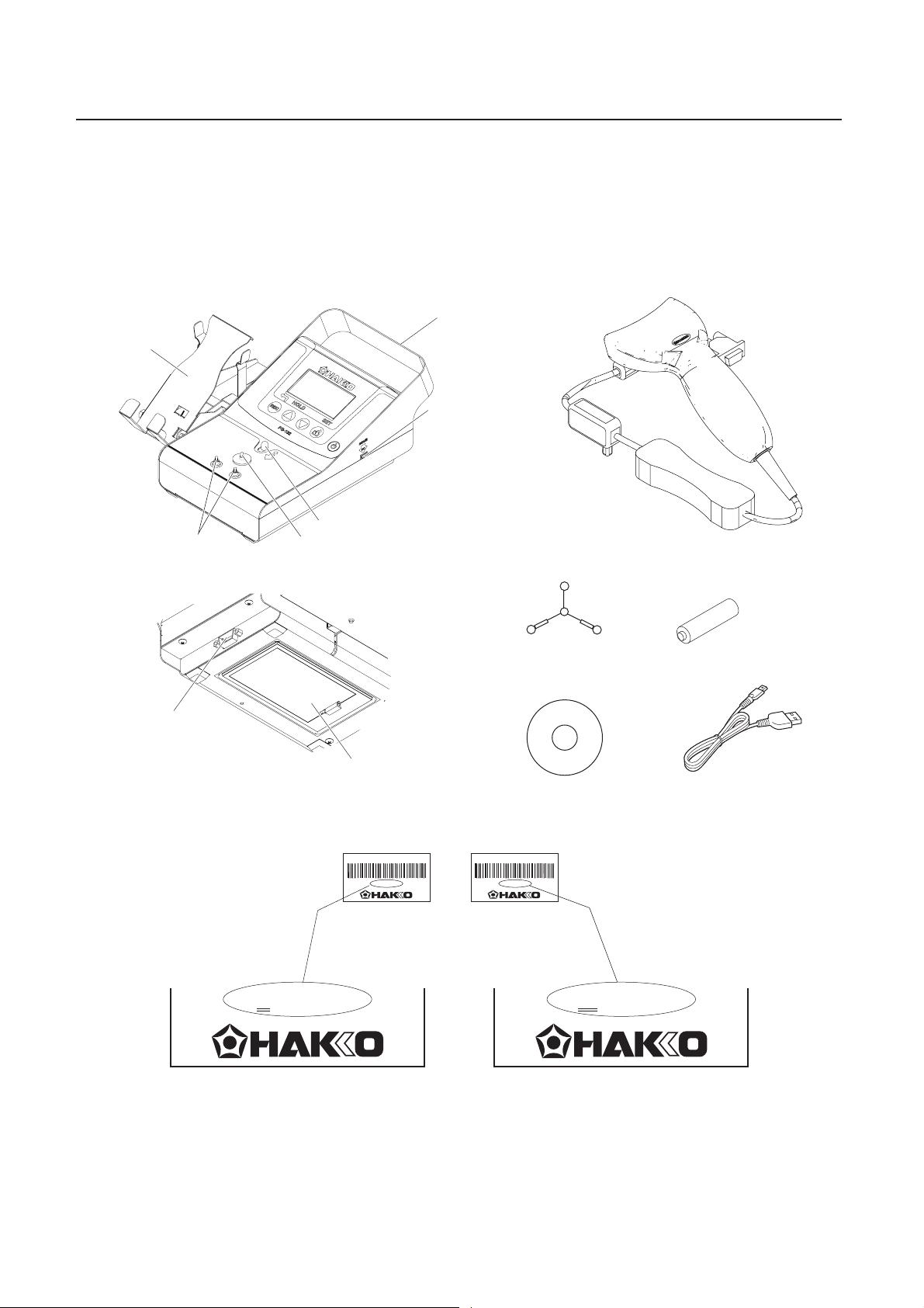
HAKKO FG-102
M
H
305
Temp ****
℃
2014/08/31/14:01
Model name
Resolution
Temperature measurement range
Applicable sensor
Measurement tolerance
Display
Power supply
Outline dimensions
Weight
Length of cord
(Barcode reader)
Length of the USB cable
USB type
Ambient temperature/humidity range
Environmental condition
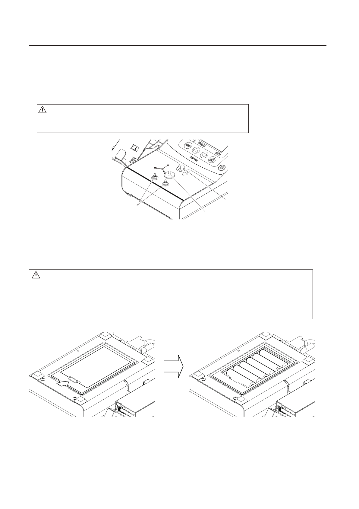
CAUTION
When using the thermometer to measure the temperature of the soldering iron tip or de-soldering
nozzle, pay great attention to the temperature of the tip or nozzle that will be as high as 200 to 450°C
(392 to 842°F). Careless handling of such a hot object may result in a burn or fire.
If the equipment is used in a manner not specified by the manufacturer, the protection provided by the
equipment may be impaired.
Warnings, cautions and notes are placed at critical points in this manual to direct the operator’s
attention to significant items. They are defined as follows:
CAUTION : Failure to comply with a CAUTION may result in injury to the operator, or damage to the
items involved. Two examples are given below.
WARNING: Failure to comply with a WARNING may result in serious injury or death.
NOTE : A NOTE indicates a procedure or point that is important to the process being described.