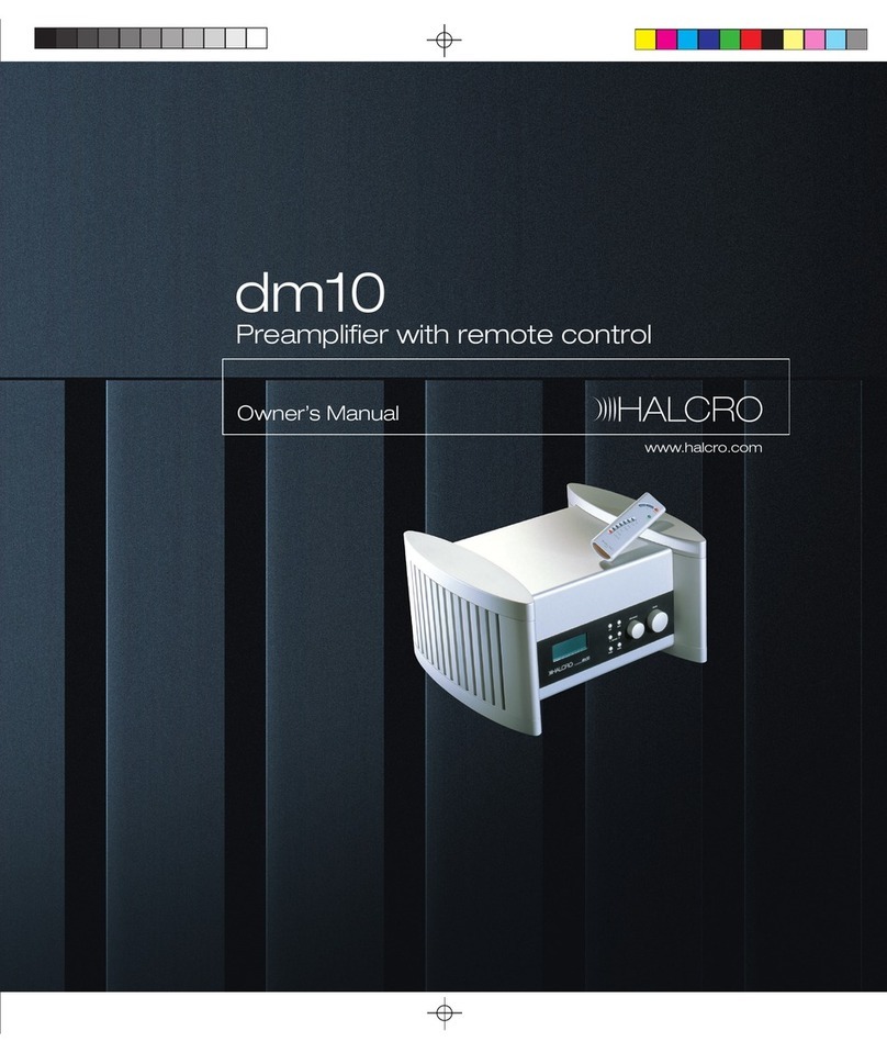
Halcro DM8 User manual

Page 1of 26
TM
dm8
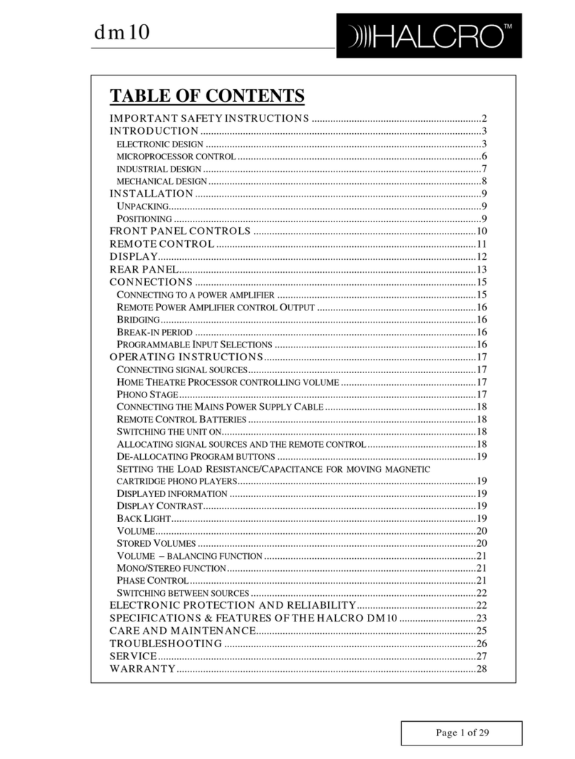
TABLE OFCONTENTS
IMPORTANTSAFETY INSTRUCTIONS.............................................................2
INTRODUCTION....................................................................................................3
ELECTRONICDESIGN.....................................................................................4
MICROPROCESSOR CONTROL.....................................................................5
INDUSTRIALDESIGN......................................................................................6
MECHANICAL DESIGN...................................................................................7
INSTALLATION.......................................................................................................8
UNPACKING .........................................................................................................8
POSITIONING ........................................................................................................8
FRONTPANEL CONTROLS.................................................................................9
REMOTE CONTROL............................................................................................10
DISPLAY..................................................................................................................10
DISPLAY..................................................................................................................11
REAR PANEL.........................................................................................................12
CONNECTIONS.....................................................................................................13
CONNECTINGTOAPOWERAMPLIFIER...............................................................13
REMOTE POWER AMPLIFIERCONTROL OUTPUT................................................14
BRIDGING...........................................................................................................14
BREAK-IN PERIOD ..............................................................................................14
PROGRAMMABLE INPUT SELECTIONS................................................................14
OPERATINGINSTRUCTIONS...........................................................................15
CONNECTINGSIGNALSOURCES .........................................................................15
HOME THEATRE PROCESSOR CONTROLLINGVOLUME ......................................15
CONNECTINGTHE MAINS POWER SUPPLY CABLE ............................................15
REMOTE CONTROL BATTERIES..........................................................................15
SWITCHINGTHE UNITON ...................................................................................16
ALLOCATINGSIGNALSOURCES AND THE REMOTE CONTROL............................16
DE-ALLOCATING PROGRAM BUTTONS ..............................................................16
DISPLAYEDINFORMATION.................................................................................17
DISPLAY CONTRAST ..........................................................................................17
BACK LIGHT.......................................................................................................17
VOLUME.............................................................................................................17
VOLUME – BALANCINGFUNCTION....................................................................18
SWITCHINGBETWEENSOURCES.........................................................................18
PHASE CONTROL................................................................................................19
ELECTRONIC PROTECTIONANDRELIABILITY.........................................19
SPECIFICATIONS&FEATURES.......................................................................20
CAREAND MAINTENANCE...............................................................................22
TROUBLESHOOTING..........................................................................................23
SERVICE..................................................................................................................24
WARRANTY...........................................................................................................25

Page 2of 26
TM
dm8
Important SafetyInstructions
CAUTION
RISK OFELECTRIC SHOCK
DONOTOPEN
Thisproduct shall be connectedtoaMAINS socket outlet witha
protective earthing connection.
OnlysuitableapprovedMAINS cords, as perEuropean
individualcountryrequirements intheCE LowVoltage Directive
Scheme, shall be usedwiththis unit.
Do notuse extensioncords: To avoidsafety hazards, use onlythe
powercord suppliedwithyour unit. We do notrecommendthat
extensioncords be usedwiththis unit.
Weighs 23 kg (50 lbs.)perunit. Shipping weight 36 kg (79 lbs)
Designedfor indoor use only. Thedm8preamplifierisnot
protectedagainst liquids.
Theunitshall notbe exposedtodrippingor splashing. Noobjects
filledwithliquids, suchas vases, shall be placedonthe
apparatus.
Nonakedflamesources, suchas lightedcandles, shouldbe
placedonthe apparatus.
Designedtooperate onanymainssupplyintherange of90Vto
240 V. 50 to60 Hz, without any internalor externalswitches.
Therearenouserserviceablecomponents insidethisunit. Do not
attempttoopenthepreamplifiercompartment: thismay expose
youtodangerous voltages andwill voidthe warranty.
Compartments aresealedat thefactory. Ifthesealsarebroken,
thewarranty will be voidandall service costs will be chargedto
the owner.
Requires F1AL250v fuse for continuedprotectionagainst the
risk offire. Neverbypass or use any othertype offuse. The fuse is
locatedonthe rearpanelinthe mainswitch.
90 -240 V
50 -60 Hz
10A

Page 3of 26
TM
dm8
Introduction
Congratulations onpurchasing the HALCRO™ dm8 preamplifier.
It has takentwoyearsandthegenerouscontributionsofleadingreviewers,
distributorsanddealersfrom aroundtheworldtodesign,thencreate, the
HALCRO™preamplifiers. We areconfidentthat thiscombinationof
expertise, alongwiththeknow-howofthehigh-endaudioindustry’sleading
ResearchandDevelopmentteamwill ensurethesuccess oftheHALCRO™
preamplifiers.
Thebriefgiventoour R&Dteam,headedby Bruce Candy, was toproduce
twomodels ofpreamplifiertosatisfy the needs ofevery audioconnoisseur:
Ÿ Lowest distortionspecifications ofany preamplifierinthe world.
Ÿ Physicaldimensionstosuitastandard domesticequipmentrack, while
retaining the stunning HALCRO™ industrialdesignsignature.
Ÿ Tractable controls.
Ÿ Superior reliability.
Ÿ Innovationindesign.
TheHALCRO™dm8&dm10 preamplifierswill add nocolorationstothe
music. WhenusedinconjunctionwithHALCRO™poweramplifier(s),all
youwill hearistheoriginalrecordingreproducedtheway theartist intended
ittosound.Notransistor or valve-addedsoundsarepresent, just alevelof
musicalpurity that was thought impossible until now.

Page 4of 26
TM
dm8
ELECTRONICDESIGN By Bruce Candy
Inkeepingwithmyphilosophyofdesign,mybasicaimwas toproduce a
preamplifierwithwhichI, personally, amquite satisfied. I sincerely hope that
others will share my satisfactionwiththese products.
As I sawit, the major issues were:
Ÿ Zero compromise onTransparency.
Ÿ Flexibility.
Ÿ Ease ofuse.
Ÿ Progressive designconcepts.
Inordertomeet thischallenge, theresultingcircuits have particular
characteristics:
Ÿ First, all circuits inthepreamp have distortionsolowthat itis
immeasurable, whetherTHD, IM etc.
Ÿ Second,all circuits inthepreamp exhibitexceptionallylownoise (see
specifications).
Ÿ Third,thereisnocompromise whateverwiththechoice ofcomponents
(Vishay resistors, FKP1 capacitors etc).
Ÿ Fourth,thecircuits arehighlyimmunetoelectromagneticinterference.
Someinputs andoutputs includebothfirst orderfiltersandcommon
mode chokes.
Ÿ Fifth,thepowersupplyandmicroprocessor circuits aredesignedfor
minimalelectromagnetic emissions (extensive 2nd to6th orderfilters).
Ÿ Sixth,thepowersupplyswitchingfrequency was chosentobe much
higherthanthe audioband(>200kHz).
Ÿ Seventh,thepowersupplyrailsareexceptionallywell regulated,
double regulationinfact (switch-mode andlinearservoloops).
Ÿ Eighth, components anddesignare selectedfor highreliability.
Thevolumecontrolisimplementedsoas toincludetwoidenticalstages in
series. This minimizes output noise.
Thedm8&dm10 preamplifiersfeaturebalanced,unbalanced,currentmode
andbridgedcurrentmodeoutputs. Thelatterconsists ofanon-invertedand
invertedcurrentoutput. Thereisalsoanunbalancedoutputfor tapeand
headphones.

Page 5of 26
TM
dm8
Audible relay noise
Thedm8&dm10 use mechanicalrelays inall switchingincludingthevolume
controlbecause they exhibit the following idealcharacteristics ;
• zero ON resistance,
• infinite OFF impedance,
• very lowOFF capacitance,
• zero distortion.
Incontrast, thenowuniversallypopularsolidstate relays/switches exhibit
none ofthese idealproperties anddetract from performance.
Hence, sonically, HALCRO™feelsthat itisworththesideeffect of
mechanicalclicking sounds whenparameters are changed.
MICROPROCESSORCONTROL By PaulRainbow
Theexcellentaudioelectronics arecomplementedandcontrolledby a number
ofhighlyintegratedmicro-controllerslocatedclose totheelectronics they
serve. Beingas nearas possibletothecontrolledelectronics allowsshort
controlpathsandvirtuallyeliminates internalconnectors, thereby greatly
increasing systemreliability.
Eachamplifierchannelhas its ownmicro-controller;thefrontpaneldisplay
anduserinterface has another.Afourthmicro-controller,locatedontherear
connector panel,co-ordinates theactivity oftheothers. Thefour micro-
controllers are linkedvia only four interconnections each.
Auniqueprogrammingfeatureofthemicroprocessor has beendeveloped
whichallowstheusertodedicate aparticularpairofinputsockets toa
specificinputdevice. Thisfeatureprovides theuserwithgreat flexibility for
connectinginputdevices tothepreamplifier.Therearpanelhas provisionto
accommodate five inputdevices intosevenphysicalpairsofinputsockets.
Thereisonepairofcurrentinputs, three pairsofbalancedinputs andthree
pairsofunbalancedinputs. Phonoinputs do not require programming as they
are permanently allocatedtothe phonosource (in the dm10).

Page 6of 26
TM
dm8
INDUSTRIALDESIGN By MaxDickison&Tony Kearney
ProductForm
Theaimwhendesigningthedm8anddm10 was tocreate apreamplifierthat
was unmistakablypartoftheHALCRO™product family, butat thesame
time a component that wouldcompliment any highendaudiosystem.
Thepreamplifierhadtositcomfortablywithinacontemporarydomestic
environment, retainthevisualsignatureoftheHALCRO™familyof
products whichdifferentiates themfrom otherhighendaudioproducts and
have anappearance that reflectedthehighleveloftechnicalinnovation.As
withotherHALCRO™products, softerformsandtextures areused,all
fastenersareconcealedandtheheatsinks areintegratedintotheexternalform
tomaintainsimple, cleanlines.
Whilst theuniquepillarformsofthepoweramplifiershave beencarried
throughtothepreamp,proportionshave beenreworkedtoallowthis
componenttobe eitherfreestandingor housedwithina standard 19” shelving
system.
ControlInterface
Knobsand buttons:
Thevolumeandinputselector knobs use auniquemagneticincremental
indexingmechanismdevelopedtoprovideaverysubtleandreliableindexing
action.Theknobs andbuttonsarefinishedinthesamesofttexturalfinishas
the pillars.
Display:
Ahigh-resolutiondisplay was choseninordertoprovidecleansimple
graphics withouttheroughedges associatedwithdisplays oflesserquality.
Thegraphiclayoutofthedisplay has beenoptimizedtogive prominence to
thefunctionsthat areviewedmost often.These includevolumelevels,
balance andinputselection.Functionsthat areaccessedless oftenare
displayedinsmallertypealongthebottom ofthescreen.These include
stereo/monoandin-phase/out-of-phase. Thevolumelevelsfor eachchannel
aredisplayedside-by-sidesothat whenthelevelsarenotequalizedtheuser
will easily notice it.

Page 7of 26
TM
dm8
Remote control:
WhendesigningtheHALCRO™Remote Control,weaimedtoreflect the
quality andformsoftheHALCRO™preamplifiers. Machinedfrom asolid
aluminumextrusion,theremote rests comfortablyinthehandwithits
minimalist array ofbuttonsfallingwithinthenaturalsweepofthethumb.
Simpleandlogicaltooperate, everyefforthas beenmadetokeepthisproduct
free ofunnecessary complexity.
MECHANICALDESIGN By Lance Hewitt
TheHALCRO™dm8anddm10 canboast theirspectacularlylownoise and
distortionspecificationswhiletheircases containinherentlynoisy digital
circuitry, includingaswitch-modepowersupply, partlyduetothe
mechanicaldesignoftheircircuitboardsandtheboxes that containthem.
Supports offoldedaluminumserve notonlyas bases towhichtheelectronics
areanchored,butalsotoshielddifferentsectionsofthecircuitryfrom one
another.
Eachoftheaudio,panelanddisplay, andpowersupplysectionsiscontained
withinits owninternalaluminumenclosure. Cables connectingtheseparate
sectionsarefewandshort, minimizingbothradiationandreceptionof
unwantedsignals.
Please enjoy the HALCRO™ audioexperience.
HALCRO™has enjoyedcreatingperfect audioreproductionfor theworld's
music connoisseurs.
Ifyouwishtocontact HALCRO™tosupplyfeedback onyour purchase or for
generalenquiries, please feelfree tocontact us:
Email: admin@halcro.com
Telephone: +61 8 8238 0807
Facsimile: +61 8 8238 0852

Page 8of 26
TM
dm8
Installation
Ensureyouhave readtheImportantSafety Instructionssectiononpage 2prior to
installingyour HALCRO™preamplifier.Ifyourequireassistance intheunpackingand
installationofyour HALCRO™ preamplifier, please contact your dealer.
Unpacking
Undo the4fastenersat thebase ofeachbox.Thenremove theupperpartofthecontainer
by liftingdirectlyupwards, beingcarefulnottorubitagainst thepreamplifier.(To have
gainedaccess tothis manualyoumust have completedthe above steps).
Remove thematerialwrappingandfoampieces, thenliftthepreamplifierfrom thebase
ofthecontainer.(It isrecommendedthat theusertake off all jewelrythat may scratchthe
unit andput onthe white cottongloves providedwiththe unit.)
Remove thecenterpiece offoaminbase oftransitcase, tolocate theremote controland
powercable.
Remove the covering from the unit. Please save it for lateruse.
Move the unit toits finallocation(see Positioning).
Important
Do not connect any cables as yet.
Safelystorethepackagingfor futurerelocationoftheunitandshippingif service is
required.
Positioning
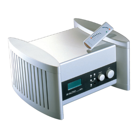
TheHALCRO™dm8preamplifiercanbe placedanywhereindoors. Thereisnoneedto
leave room aroundtheunittoallowittobreathe. Thedm8does notgenerate significant
amounts ofheat.
To ensureultimate performance andtoavoidpotentialsafety hazards, place theunitona
firm andlevelsurface. Whenplacingtheunitonashelf,be certainthat theshelf and
mounting hardware cansupport the weight ofthe product.

Page 9of 26
TM
dm8
Front PanelControls
1. LCD Information
Display
2. Balance ControlLeft
3. Standby/Onbutton
4. Mute button
5. Balance ControlRight
6. Input Select Control
7. Volume Control
8. Phase button
9. Remote Sensor
Window
1. LCDInformationDisplay: This
display deliversmessages andsystem
statustoassist youinoperatingtheunit.
See page 11 for acomplete breakdownon
the display.
2. Balance ControlLeft:Usingthis
buttoninconjunctionwithBalance
ControlRight(Fig1, 5),theusercan
change therelative volumefor theleft
andrightchannels. PressingtheLeft
buttonwill increase thevolumeonthe
lefthandchannelanddecrease the
volume onthe right.
3. Standby/Onbutton: TheHALCRO™
dm8isdesignedtoremaininstandby
modewhennotinuse. Thisbuttonwill
toggletheunitbetweenStandby andOn.
To turntheunitoff completely, use the
rearpanelMasterPowerSwitch(Fig 6, 6).
4. Mutebutton:Depressingthisbutton
will Mute the output tothe speakers.
5. Balance ControlRight:Usingthis
buttoninconjunctionwithBalance
ControlLeft(Fig1, 2),theusercan
change therelative volumefor theleft
andrightchannels. PressingtheRight
buttonwill increase thevolumeonthe
righthandchannelanddecrease the
volume onthe left.
6. InputSelectcontrol:Byturningthis
knob, thepreamplifierwill scroll through
all the programmedinputdevices (CD
player,Tuner,DVD,etc.)attachedtothe
unit.
Figure 1

Page 10 of 26
TM
dm8
7. Volumecontrol:Turnthisknob
clockwise toincrease thevolumeand
counter-clockwise todecrease the
volume. To mute thesystem,whenthe
speakersarebalanced,continuetoturn
theknobcounter-clockwise until the
word MUTE appearsonthedisplay, or
press the Mute button(Fig 1, 4)
8Phase Button:Depressingthisbutton
will toggletheunitbetweenin-phase and
out-of-phase mode.
9Remotesensorwindow:Behindthis
windowisasensor that receives infrared
signalsfrom theremote control.Aimthe
remote at thisarea anddo notblock or
coverthis sensor window.
Remote Control
1. Volume buttons
2. Mute button
3. Standby/Onbutton
4. SignalSource buttons
5. Functionbutton
1. Volume buttons: For
volume controlandalso
usedinconjunctionwith
the functionbuttonfor
various functionselections.
2. Mute button: Press to
Mute the sound, press
againtoreactivate the
sound.
3. Standby/Onbutton:
Press totoggle the system
betweenStandby andOn.
4. Signalsource buttons:
Press toselect any one of5
signalsources onthe dm8.
5. Functionbutton: Press
tochoose the following
functions: speakerbalance,
inandout ofphase andto
toggle the systembetween
stereoandmono. See
relevant operating
instructions for full details.
Figure 2
Note: Remote controltakes 3 xAAA batteries (supplied)

Page 11 of 26
TM
dm8
Display
1. MainInformationDisplay
2. SignalSource Indicators
3. SignalSource LocationIndicator
4. Phase Indicator
1. MainInformationDisplay: The
informationprovidedonthisdisplay
changes dependingonwhat functionis
currently being processed.
Innormaluse itwill display thevolume
ofboththeleftandrightofthesystem
(Fig 4).
Whenadifferentinputsignalsource is
selecteditwill appearonthemain
display (Fig 5)for a fewseconds.
2. SignalSource Indicator:Displays the
signalsource whichis currently selected.
3. SignalSource LocationIndicator:
Displays whichinputthesignalsource
has beenconnectedto.
4. Phase Indicator:Displays whetherthe
unit is in- or out-of-phase.
Figure 3
Figure 5
Figure 4

Page 12 of 26
TM
dm8
RearPanel
1. Programmable inputs
2. Programbuttons
3. Tape Monitor outputs
4. Output sockets
5. Remote sensor window
6. Mainspowerswitch,
socket andfuse holder
7. Remote Power
Amplifieroutput
8. Output selector switch
1. Programmable inputs: Provides
connectiontoyour signalsources. It does
not matterwhichinput eachsource is
connectedto, as these inputs are allocated
using the remote control.
2. Programbuttons: Allowstheinputs tobe
programmedtotheremote control.They
will remainilluminatedonce they have been
allocated–see Connecting signalsources and
allocating signalsources and theremote control
(page 15/16)
3. Tape Monitoroutputs: For recording
direct totape.
4. Outputsockets: Provide connect from the
Pre AmplifiertoPowerAmplifier(s).
5Remotesensorwindow:Behindthis
windowisasensor that receives infrared
signalsfrom theremote control.Aimthe
remote at this area.
6. Mainspowerswitch,socketand fuse
holder:Once thedm8has been
programmed,themainpowerswitchcanbe
left onandthedm8leftinstandby whennot
inuse. Ifthemainpowerswitchisturned
off, all programming is storedinmemory.
7. RemotePowerAmplifierControl
output:Connect acablefrom thisoutputto
thepoweramplifier(s)andthedm10 will
switchthepoweramplifier(s)between
Standby andOn.
8. Outputselectorswitch: Allowstheuser
toselect thetypeofoutputrequired,
Balanced,UnbalancedandCurrent. see
Comments on thedifferentdm8Outputs (page
14).
Figure 6

Page 13 of 26
TM
dm8
Connections
Connecting to a poweramplifier
Eachdm8 has:
2pairsofunbalancedcurrentoutputs. 1pairisusedinun-bridgedmodeandbothareused
for drivingbridgedamplifiers, 2pairsofunbalancedvoltage outputs and2pairsofbalanced
voltage outputs. Select themethod youwishtooperate your poweramplifiersin,andconnect
the 2 units using highquality cables.
Outputs are color coded:
Positive +, Right channel(RedBezel).
Negative -, Left channel(White Bezel).
Thedm8will controlpoweramplifiersfrom balancedandunbalancedvoltage sources, as well
as anunbalancedcurrentsource. Thedm8will alsocontrolpoweramplifiersinbridgedpair
configuration.Custom madecables arerequiredtorunbridgedpoweramplifiersfrom the
balancedVoltage Output. (Fig 7).
Comments on the differentdm8 Outputs
Thebalancedvoltage outputs or current-mode outputs are most desirable for minimising earth
loop generatedmainshumandripple, or highfrequency interference if they areaproblem.
Earthloop generatedmainshumandripple, or highfrequency interference shouldnotbe a
problemunless the source equipment is poorly designed.
PowerAmplifierswithcurrent-modeinputs arerareandaremost likelytohave anRCAinput
socket. The advantages ofthis are:
Ÿ Earthloop generatedmains humandripple are minimized.
Ÿ Cable, plugandsocket-generatedinterference isminimized(from poor connections
whichmay be affectedby soundvibrationfor example).
Theunbalancedoutputisquite satisfactorysolongas earthloop generatedmainshumand
ripple are not a problem.
Figure 7

Page 14 of 26
TM
dm8
Remote PowerAmplifiercontrolOutput
Thedm10 has aremote poweramplifiercontroloutput(fig6,15)whichwill remotelyswitch
theHALCRO™amplifiersfrom Standby toOn.Cables canbe purchasedthroughHALCRO™
for details please email us at: service@halcro.com .
Bridging
Thedm8will controlbridgedpoweramplifiers. For detailsplease email usat:
service@halcro.com Abridging kit canbe purchasedthroughHALCRO™.
Break-in period
Thedm8does notrequireabreak-in period.Theelectronicbreak-in period iscompletedat the
factory.
Programmable InputSelections
Thedm8has sevenavailablepairsofprogrammableinputconnectors, three unbalanced,three
balancedvoltage inputs andoneunbalancedcurrentinput. All inputs that have asignal
source connectedmust be programmedby theremote control.Anyinputcanbe programmed
toconnect anysource. Eachbuttonontheremote controlcanhave onlyonesignalsource
programmedtoit at any time.
Input
Modes Requiredoutput
source impedance Inputimpedance
Unbalancedcurrent
input RCA: Infinite source
impedance 50ohminput impedance
Balancedvoltage input XLR: Lowsource
impedance 10kohm+10kohminput
impedance
Unbalancedvoltage
input RCA: Lowsource
impedance 10kohminput impedance

Page 15 of 26
TM
dm8
OperatingInstructions
Connecting signalsources
Asasafety precautionplease ensurethat theunitisnotconnectedtothemainspowerwhile
connecting signalsources.
Whenyouoriginally receive your preamplifierall the inputs are de-allocated.
Ifyouarechangingyour signalsource units, de-allocate theinputsource first –follow De-
allocating ProgramButtonsinstructions (Page 16)
Connect all signalsource units (e.g. CD player)totheterminals(Fig6, 1)at therearofthe
preamplifier, make note ofwhichinput eachsignalsource unit is connectedto.
Home Theatre Processorcontrolling volume
Asasafety precautionplease ensurethat theunitisnotconnectedtothemainspowerwhile
connecting a Home Theatre Processor.
Connect your HomeTheatreProcessor toanyoftheprogrammableinputs at therearofthe
preamplifier.
Programthepreamplifiertotheunitusing Allocating signalsources and theremote control on
page 19. We recommendyouuse the DVDfunction.
To set thepreamplifiertooperate withzero gain,adjust bothvolumechannelsto0.0db. The
preamplifierwill thenhave noeffect onthevolume. You will nowbe abletocontrolthe
volume ofyour systemby using your Home Theatre Processor volume control.
Connecting the Mains PowerSupply Cable
Plug the mainpowercable intothe dm8’s mains powersocket onthe rearofthe unit. (Fig 6, 6).
Remote ControlBatteries
Remove the battery coverfrom therearoftheunit, insertthethree suppliedAAA batteries into
the unit (ensure that the polarity is correct). Refit the battery cover.
Ifthe remote controlwill not be usedfor a period longerthan1 monthremove the batteries.

Page 16 of 26
TM
dm8
Switching the unit on
Switchthe mainpowerswitchtoOn.
Whentheunitisswitchedonat themainpowerswitch(Fig 6, 6)the pre-amplifierwill gointo
Standby mode.
Switchtheunitonby pressingtheStandby/Onbuttonontheunitor theremote control.To
returnthe unit toStandby mode press the Standby/Onbuttonagain.
Note: To continuetheset up process, theunit must beOn, notin Standby.
Allocating signalsources and the remote control
All inputs must be allocatedusingtheremote control(Fig7).Note:ThePhonoselectionis
permanently allocatedtothe Phonoinputs.
Once thesignalsource units (e.g. CD player)have beenconnectedtotheinputconnector
terminals(Fig6, 7)at therearofthepreamplifier,ensurethat thepreamplifierisOn,notin
Standby mode.
Depress theapplicableprogrambutton(situatedabove theconnectors)andsimultaneously
point the remote controltoa remote sensor windowandpress thebuttonontheremote control
whichbest describes the signalsource unit youhave connected.
Theprogrambuttonwill flashtwice andwill remainilluminated,indicatingthat thispairof
inputconnectorsarenowallocatedtotheselectedsignalsource unit. Repeat thisprocess for
all signalsource units (maximum5 plus Phono).
Ifthedevice labelthat isbeingdepressedontheremote controlhas beenpreviouslyallocated
toanotherconnector pair, this pairwill nowbe de-allocated.
De-allocating ProgramButtons
Note: Ensurethelocationbeingde-allocatedisnotthecurrentlyselectedinput, thecurrently
selectedinput cannot be de-allocated.
Press andholdtheapplicableprogrambuttonandsimultaneouslypointtheremote controlto
aremote sensor windowandpress theMute button.TheProgramButtonwill flashtwice and
thenremainoff.Thisinputhas nowbeende-allocatedandcanbe usedfor anothersignal
source unit.

Page 17 of 26
TM
dm8
Displayed information
Innormaluse thecenterofthedisplay will display thevolumeofboththeleftandrightofthe
system. Whena different signalsource is selected, itwill appearinthecenterofthedisplay for
a fewseconds (fig3, fig4).
Display Contrast
To adjust the display contrast, press andholdany ofthe ProgramButtons onthe rearpanel
(fig 6, 8)andturnthe Volume controlonthe front paneluntil the desiredcontrast is achieved.
Back Light
Thebacklightcanbe turnedonandoff by usingtheremote control.Press thefunctionbutton
once (fig 7, 5)thenthe Mute button(fig 7, 2)totoggle the back light onandoff.
Volume
Afterpowerupandswitchingfrom Standby toON the preamplifierwill enterthe mode it was
last inwhenthe powerwas turnedoff.
FrontPanel:
To change theoverall volumeoftheunit, use theVolumeControlKnob(Fig1, 7).Turnknob
clockwise toincrease thevolume(themaximumvolumeis+20db)andcounter-clockwise to
decrease the volume (the minimumvolume is -60db).
To mute thesystem,press theMute button(Fig1, 4),theoutputtothepowerampsisthen
disabledThedisplay will showtheword MUTE.IftheMute buttonor volumebuttonis
pressedthe output tothe poweramplifiers is reactivated.
Remote Control:
To change theoverall volumeoftheunit, use thevolumebuttonsontheremote control(Fig
2,1)
To Mute theloudspeakers, press theMute button(Fig2,2).To un-mute theloudspeakerspress
the Mute buttonagainor press eithervolume button.

Page 18 of 26
TM
dm8
Volume – balancing function
Thevolumecanbe evenlydistributedthoughthespeakersor onechannelcanbe louderthan
theother.To equalise theoutputs ofthespeakerstothesamevolume, depress boththeL&R
balance buttons (Fig1, 4&7)onthe front ofthe unit at the same time.
FrontPanel:
UsingeithertheBalance ControlRight(Fig1, 5)or theBalance ControlLeft(Fig1, 2),theuser
canchange therelative volumefor theleftandrightchannels. DepressingtheRightbutton
will increase the volume onthe right handchannelanddecrease the volume onthe left.
To change theoverall volumeoftheunit, use theVolumeControlKnob(Fig1, 7).Turnknob
clockwise toincrease thevolumeandcounter-clockwise todecrease thevolume. To mute the
system,whenthespeakersarebalanced,continuetoturntheknobcounter-clockwise until the
word MUTE appears onthe display, or press the Mute switch(Fig 1, 4).
Remote Control
UsingtheFunctionkey ontheremote controltheusercanchange therelative volumefor the
left andright channels.
Depress thefunctionkey once (Fig2, 5).Thedisplay onthepreamplifier(Fig3)will display
BALANCE,thenuse theVolumebuttonsontheremote control.Depressingthe-VOLbutton
will increase thevolumeontheleftanddecrease thevolumeontheright. Depressingthe+
VOLbuttonwill increase the volume onthe right anddecrease the volume onthe left.
Thevolumecanbe evenlydistributedthroughthespeakersor onechannelcanbe louderthan
theother.To balance theoutputs ofthespeakerstothesamevolume, depress boththeL&R
(Fig1, 2&5)balance buttons onthe front ofthe unit at the same time.
Switching between sources
To select adevice, press theappropriate buttonontheremote controlor turntheselector knob
onthefrontpaneluntil thedevice yourequire appears inthe centerofthe display. Aftera few
seconds, thecenterofthedisplay will reverts todisplayingthevolumelevel,thoughthe
selectedprogramsource will remainonthelowerlefthandcornerofthedisplay. Only
allocateddevices are available. Note: The PhonoInput is always allocated.
Ifasource isselected(eitherthroughthefrontpanelor remote control) andthecorrect source
isnotselected,ensurethat the programbuttonadjacent tothe input connectors for the selected
source isilluminated.Ifitisnot, these inputconnectorswill needtobe re-allocated,referto
Connecting signalsources and Allocating signalsources and theremote control, page 19

Page 19 of 26
TM
dm8
Phase Control
To toggletheunitbetweenin-phase andout-of-phase modedepress thephase switchonthe
frontpanel(Fig1,10)or depress thefunctionkey (Fig7, 5)ontheremote controltwice, the
display (Fig3)will display Inor Out, nowpress eitherofthevolumebuttonsontheremote
controltotoggle the unit betweenin-phase andout-of-phase mode.
ElectronicProtectionand Reliability
Components
Our components are selectednot only for performance, but reliability as well.
For Example:
All HALCRO™electrolyticcapacitorsareratedat aminimumof105 degrees Cinsteadofthe
usual85 degrees Crating. The operationallife ofelectrolytic capacitors is severely shortenedat
temperatures neartheirmaximumtemperature rating. This is showninthe table below.
All HALCRO™integratedcircuits areat least “industrialgrade” ratherthantheusual
“commercialgrade.” Industrialgradecomponents areratedat least from –40 degrees Cto+85
degrees Cwhereas commercialgradecomponents areonlyratedbetween0to70 degrees C.In
addition,theelectronicspecificationsofindustrialgradecomponents aresuperior to
commercialgrade.
Electrolytic
capacitor
temperature
rating
Meanlifetime
at 40 degrees
Centigrade
Meanlifetime
at 85 degrees
Centigrade
Meanlifetime
at 105 degrees
Centigrade
85 C(most
commonly
used)
50,000 Hours 2,000 Hours (0)
105 C(usedin
HALCRO™
preamplifiers)
180,000 Hours 8,000 Hours 2,000 Hours
Typicaldata
Mainstransientoverload protection
Themainsinputisprotectedagainst all butthemost severemainsinputtransients. Two
independent circuits achieve this.

Page 20 of 26
TM
dm8
SPECIFICATIONS&FEATURES
HALCRO dm8
Remote ControlPreamplifier
Inputs
§ 3RCAUnbalanced Voltage Mode
§ 3XLRBalanced Voltage Mode
§ 1RCAUnbalanced CurrentMode
§ Any5of the above I/Psare user
programmable torespond tothe device
names: CD, DVD, Tuner, Tape, Aux.
Outputs
§ 2Pair RCAUnbalanced Voltage Mode,
Bridgeable
§ 2Pair XLRBalanced Voltage Mode,
Bridgeable
§ 2Pair RCAUnbalanced CurrentMode,
1pair for un-bridged connection, the
other pair used inbridged mode
§ 1Pair RCATape output
§ 6-pinXLRpower ON/OFF, pulsed and
leveloutput control
Powersupply
Switch-mode, >200kHzCW, 4thorder
mains filter, 4thorder supply rail filter.
EMCfully complieswithEMCand CE
standards. Circuit contains extensive mains
transientprotection and fault sensing
protection.
85-240VAC, 50-60Hz
Powerconsumption.
100Wmax viaIECinput
Mains voltage.
All voltagesfrom 85VACthroughto
240VACat50Hzthroughto60Hzor 120V
throughto340VD.C. (Power supply
will operate up to270VACbut IECsockets
rated up to240Vby regulatoryauthorities.)
Remote Control: 3x AAA batteries
Dimensions
Ÿ Width: 448mm, 17.64 inches
Ÿ Depth: 400mm, 15.74 inches
Ÿ Height: 240mm, 9.44 inches
Ÿ Weight: 22.5kg, 49.6lbs
ShippingDimensions
-InTimbercase
Ÿ Width: 585mm, 23 inches
Ÿ Depth: 535mm, 21 inches
Ÿ Height: 515mm, 20 inches
Ÿ Weight: 36 kg, 79.4lbs
RemoteControl dimensions
Ÿ Length: 183mm, 7.2inches
Ÿ Width: 50mm, 1.96 inches
Ÿ Thickness: 24mm, .94 inches
Ÿ Weight: 280gm, .6lbs
Gain
Un-balanced and balanced -60dB to+20dB
setby volume control
Input impedance
10kohm +10kohm balanced
10kohm unbalanced
50ohms for currentmode
Output impedance
170 +170ohms balanced and 170ohms
unbalanced.
>30kohms currentmode
340ohms tape
Distortion
Unmeasurable- below noise floor.
Atfull specified output, <250 partsper
billion (-132dB) for balanced and un-
balanced and currentmodes
PCB
4-layer PCBsfor ultrahighaccuracy
reference potentials
Volume control
-60dB to+20dB in0.5dB steps.
Other manuals for DM8
1
Table of contents
Other Halcro Amplifier manuals

Halcro
Halcro SSP100 User manual

Halcro
Halcro MC70 Quick start guide

Halcro
Halcro MC30 Quick start guide

Halcro
Halcro MC20 Quick start guide

Halcro
Halcro DM10 User manual

Halcro
Halcro MC70 User manual

Halcro
Halcro MC50 Quick start guide

Halcro
Halcro Eclipse mono User manual

Halcro
Halcro MC30 User manual

Halcro
Halcro DM8 User manual
Popular Amplifier manuals by other brands

Phoenix Gold
Phoenix Gold XS 2200 user guide

KAM
KAM KBA Series instruction manual

Phil Jones Bass
Phil Jones Bass MICRO 7 owner's manual

Key Digital
Key Digital Chroma KD-HDMI2X4P operating instructions

Sundown Audio
Sundown Audio SFB Series owner's manual

Niles
Niles SI-1230 Series 2 Features and specifications