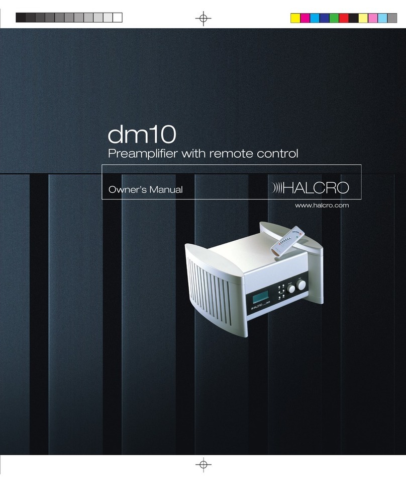
Halcro DM10 User manual

Page 1of 29
TM
dm10
TABLE OF CONTENTS
IMPORTANTSAFETYINSTRUCTIONS................................................................2
INTRODUCTION..........................................................................................................3
ELECTRONICDESIGN ........................................................................................................3
MICROPROCESSOR CONTROL............................................................................................6
INDUSTRIAL DESIGN .........................................................................................................7
MECHANICAL DESIGN.......................................................................................................8
INSTALLATION............................................................................................................9
UNPACKING......................................................................................................................9
POSITIONING ....................................................................................................................9
FRONTPANELCONTROLS....................................................................................10
REMOTE CONTROL..................................................................................................11
DISPLAY........................................................................................................................12
REARPANEL................................................................................................................13
CONNECTIONS..........................................................................................................15
CONNECTINGTO APOWER AMPLIFIER ...........................................................................15
REMOTE POWER AMPLIFIER CONTROL OUTPUT ............................................................16
BRIDGING.......................................................................................................................16
BREAK-INPERIOD ..........................................................................................................16
PROGRAMMABLE INPUT SELECTIONS ............................................................................16
OPERATING INSTRUCTIONS................................................................................17
CONNECTINGSIGNAL SOURCES......................................................................................17
HOME THEATRE PROCESSOR CONTROLLING VOLUME ...................................................17
PHONO STAGE................................................................................................................17
CONNECTINGTHE MAINS POWER SUPPLY CABLE.........................................................18
REMOTE CONTROL BATTERIES......................................................................................18
SWITCHING THE UNITON................................................................................................18
ALLOCATING SIGNAL SOURCES AND THE REMOTE CONTROL.........................................18
DE-ALLOCATING PROGRAMBUTTONS ...........................................................................19
SETTING THE LOAD RESISTANCE/CAPACITANCE FOR MOVING MAGNETIC
CARTRIDGE PHONO PLAYERS..........................................................................................19
DISPLAYED INFORMATION .............................................................................................19
DISPLAY CONTRAST.......................................................................................................19
BACK LIGHT...................................................................................................................19
VOLUME.........................................................................................................................20
STORED VOLUMES .........................................................................................................20
VOLUME– BALANCING FUNCTION................................................................................21
MONO/STEREOFUNCTION..............................................................................................21
PHASE CONTROL............................................................................................................21
SWITCHING BETWEEN SOURCES.....................................................................................22
ELECTRONICPROTECTION AND RELIABILITY.............................................22
SPECIFICATIONS&FEATURESOFTHEHALCRODM10.............................23
CAREAND MAINTENANCE...................................................................................25
TROUBLESHOOTING...............................................................................................26
SERVICE........................................................................................................................27
WARRANTY.................................................................................................................28
Page 2of 29
TM
dm10
Important SafetyInstructions
CAUTION
RISK OFELECTRIC SHOCK
DONOTOPEN
Thisunitshall be connectedtoaMAINS socket outlet witha
protective earthing connection.
OnlysuitableapprovedMAINS cords, as perEuropeanindividual
countryrequirements intheCE LowVoltage Directive Scheme, shall
be usedwiththis unit.
Do notuse extensioncords: To avoidsafety hazards, use onlythe
powercord suppliedwithyour unit. We do notrecommendthat
extensioncords be usedwiththis unit.
Weighs 23 kg (50 lbs.)perunit. Shipping weight 36 kg (79 lbs)
Designedfor indoor use only. Thedm10 preamplifieris not protected
against liquids.
Theunitshall notbe exposedtodrippingor splashing. Noobjects
filledwithliquids, suchas vases, shall be placedonthe apparatus.
Nonakedflamesources, suchas lightedcandles, shouldbe placedon
the unit.
Designedtooperate onanymainssupplyintherange of90Vto240
V, 50 to60 Hz, without any internalor externalswitches.
Do notattempttoopentheunitas this will voidthewarranty and
will expose youtodangerous voltages.
Compartments aresealedat thefactory. Ifthesealsarebroken,the
warranty will be voidandall service costs will be chargedtothe
owner.
Requires F1AL250v fuse for continuedprotectionagainst therisk of
fire. Neverbypass or use anyothertypeoffuse. Thefuse islocated
onthe rearpanelinthe mainswitch.
90 -240 V
50 -60 Hz

Page 3of 29
TM
dm10
Introduction
Congratulations onpurchasing the HALCRO™ dm10 preamplifier.
It has takentwoyearsandthegenerouscontributionsofleadingreviewers,
distributorsanddealersfrom aroundtheworldtodesign,thencreate, the
HALCRO™preamplifiers. We areconfidentthat thiscombinationof
expertise, alongwiththeknow-howofthehigh-endaudioindustry’sleading
ResearchandDevelopmentteamwill ensurethesuccess oftheHalcro
preamplifiers.
Thebriefgiventoour R&Dteam,headedby Bruce Candy, was toproduce
twomodels ofpreamplifiertosatisfy the needs ofevery audioconnoisseur:
Ÿ Lowest distortionspecifications ofany preamplifierinthe world.
Ÿ Physicaldimensionstosuitastandard domesticequipmentrack, while
retaining the stunning Halcro industrialdesignsignature.
Ÿ Tractable controls.
Ÿ Superior reliability.
Ÿ Innovationindesign.
TheHALCRO™dm8&dm10 preamplifierswill add nocolorationstothe
music. WhenusedinconjunctionwithHALCRO™poweramplifiers, all you
will hearistheoriginalrecordingreproducedtheway theartist intendeditto
sound.Notransistor or valve-addedsounds are present, just a levelofmusical
purity that was thought impossible until now.
ELECTRONICDESIGN By Bruce Candy
Inkeepingwithmyphilosophyofdesign,mybasicaimwas toproduce a
preamplifierwithwhichI, personally, amquite satisfied. I sincerely hope that
others will share my satisfactionwiththese products.
As I sawit, the major issues were:
Ÿ Zero compromise onTransparency.
Ÿ Flexibility.
Ÿ Ease ofuse.
Ÿ Progressive designconcepts.

Page 4of 29
TM
dm10
Inordertomeet thischallenge, theresultingcircuits have particular
characteristics:
Ÿ First, all circuits inthepreamp have distortionsolowthat itis
immeasurable, whetherTHD, IM etc.
Ÿ Second,all circuits inthepreamp exhibitexceptionallylownoise (see
specifications).
Ÿ Third,thereisnocompromise whateverwiththechoice ofcomponents
(Vishay resistors, FKP1 capacitors etc).
Ÿ Fourth,thecircuits arehighlyimmunetoelectromagneticinterference.
Someinputs andoutputs includebothfirst orderfiltersandcommon
mode chokes.
Ÿ Fifth,thepowersupplyandmicroprocessor circuits aredesignedfor
minimalelectromagnetic emissions (extensive 2nd to6th orderfilters).
Ÿ Sixth,thepowersupplyswitchingfrequency was chosentobe much
higherthanthe audioband(>200kHz).
Ÿ Seventh,thepowersupplyrailsareexceptionallywell regulated,
double regulationinfact (switch-mode andlinearservoloops).
Ÿ Eighth, components anddesignare selectedfor highreliability.
Thefigurebelowshowsafunctionalblock diagramofthepreamplifier
(Diagram1).Ascanbe seen,thephonostage has 4stages. Firstly, thereisan
ultralownoise inputstage withagainofx20 for movingcoil cartridges. This
canbe switchedout ofthe circuit train.
Diagram1

Page 5of 29
TM
dm10
Thefirst stage isfollowedby ahighinputimpedance (FETinput)lownoise
amplifierwithagainselectabletox4or x8. Theoutputofthisstage isfedto
aninvertingamplifierwithagainselectedtobe x-2if thehighinput
impedance amplifierstage gainisselectedtobe x4, or x-1if thehighinput
impedance amplifierstage isselectedtobe x8. (The“minus” indicates
inverting.)Theoutputoftheinvertingamplifierisconnectedback tothe high
inputimpedance amplifierstage inputviaacontinuouslyvariable
potentiometer.Acontinuouslyvariablecapacitor isalsoconnectedtothis
inputandtoground.Thevariableresistor andcapacitor set theload
impedance ofthehighinputimpedance amplifierstage andact toload
moving magnet cartridges.
Thisconfigurationformsanactive load.Thevariablecapacitance sets theload
capacitance andtheloadresistance is1/8th ofthevalueofthepotentiometer
resistance. Thisconfigurationlowersthenoise floor at highfrequency, andits
attributes are describedbelow.
Theoutputofthehighinputimpedance amplifierstage is, as well,fedtoa
15Hz3
rd orderhigh-pass Besselfilter.Thisacts as a“rumble-filter.”
FollowingthisistheRIAA equalizationstage. TheRIAA equalizationadheres
tothe RIAA specificationwithin0.25dB at all frequencies.
TheoutputofthisRIAA stage isfedtoalownoise inputselector stage which
has againof2. Intruth,if aphonoinputisselected,thisgaincanbe set to
either1or 2, dependinguponthegainoftheselectedphonoinput. Some
inputs arebalancedinputs andoneinputisacurrentinputwithaload
impedance of51 ohms, for optimalinter-connect loadmatching. The
equivalentinputnoise ofthevoltage inputs isapproximately3.5nV/sqrt(Hz),
andthat ofthe current input is 13pA/sqrt(Hz).
Thevolumecontrolisimplementedsoas toincludetwoidenticalstages in
series. This minimizes output noise.
Thedm8&dm10 preamplifiersfeaturebalanced,unbalanced,currentmode
andbridgedcurrentmodeoutputs. Thelatterconsists ofanon-invertedand
invertedcurrentoutput. Thereisalsoanunbalancedoutputfor tapeand
headphones.

Page 6of 29
TM
dm10
Audible relay noise
Thedm8&dm10 use mechanicalrelays inall switchingincludingthevolume
controlbecause they exhibit the following idealcharacteristics:
Ÿ zero ON resistance,
Ÿ infinite OFF impedance,
Ÿ very lowOFF capacitance,
Ÿ zero distortion.
Incontrast, thenowuniversallypopularsolidstate relays/switches exhibit
noneofthese idealproperties anddetract from performance. Hence,
sonically, HALCRO™feelsthat itisworththesideeffect ofmechanical
clicking sounds whenparameters are changed.
MICROPROCESSORCONTROL By PaulRainbow
Theexcellentaudioelectronics arecomplementedandcontrolledby a number
ofhighlyintegratedmicro-controllerslocatedclose totheelectronics they
serve. Beingas nearas possibletothecontrolledelectronics allowsshort
controlpathsandvirtuallyeliminates internalconnectors, thereby greatly
increasing systemreliability.
Eachamplifierchannelhas its ownmicro-controller;thefrontpaneldisplay
anduserinterface has another.Afourthmicro-controller,locatedontherear
connector panel,co-ordinates theactivity oftheothers. Thefour micro-
controllers are linkedvia only four interconnections each.
Auniqueprogrammingfeatureofthemicroprocessor has beendeveloped
whichallowstheusertodedicate aparticularpairofinputsockets toa
specificinputdevice. Thisfeatureprovides theuserwithgreat flexibility for
connectinginputdevices tothepreamplifier.Therearpanelhas provisionto
accommodate sixinput devices intonine physicalpairs ofinputsockets. There
are twopairs ofdedicatedphonoinputs, one pairofcurrentinputs, three pairs
ofbalancedinputs andthree pairsofunbalancedinputs. Phonoinputs do not
require programming as they are permanently allocatedtothe phonosource.

Page 7of 29
TM
dm10
INDUSTRIALDESIGN By MaxDickison&Tony Kearney
ProductForm
Theaimwhendesigningthedm8&dm10 was tocreate apreamplifierthat
was unmistakablypartoftheHALCRO™product family, butat thesame
time a component that wouldcompliment any highendaudiosystem.
Thepreamplifierhadtositcomfortablywithinacontemporarydomestic
environment, retainthevisualsignatureoftheHALCRO™familyof
products whichdifferentiates themfrom otherhighendaudioproducts and
have anappearance that reflectedthehighleveloftechnicalinnovation.As
withotherHALCRO™products, softerformsandtextures areused,all
fastenersareconcealedandtheheatsinks areintegratedintotheexternalform
tomaintainsimple, cleanlines.
Whilst theuniquepillarformsofthepoweramplifiershave beencarried
throughtothepreamp,proportionshave beenreworkedtoallowthis
componenttobe eitherfreestandingor housedwithina standard 19” shelving
system.
ControlInterface
Knobsand buttons:
Thevolumeandinputselector knobs use auniquemagneticincremental
indexingmechanismdevelopedtoprovideaverysubtleandreliableindexing
action.Theknobs andbuttonsarefinishedinthesamesofttexturalfinishas
the pillars.
Display:
Ahigh-resolutiondisplay was choseninordertoprovidecleansimple
graphics withouttheroughedges associatedwithdisplays oflesserquality.
Thegraphiclayoutofthedisplay has beenoptimizedtogive prominence to
thefunctionsthat areviewedmost often.These includevolumelevels,
balance andinputselection.Functionsthat areaccessedless oftenare
displayedinsmallertypealongthebottom ofthescreen.These include
stereo/monoandinor out-of-phase. Thevolumelevelsfor eachchannelare
displayedside-by-sidesothat whenthelevelsarenotequalizedtheuserwill
easily notice it.

Page 8of 29
TM
dm10
Remote control:
WhendesigningtheHALCRO™Remote Control,weaimedtoreflect the
quality andformsoftheHALCRO™preamplifiers. Machinedfrom asolid
aluminumextrusion,theremote rests comfortablyintherighthandwithits
minimalist array ofbuttonsfallingwithinthenaturalsweepofthethumb.
Simpleandlogicaltooperate, everyefforthas beenmadetokeepthisproduct
free ofunnecessary complexity.
MECHANICALDESIGN By Lance Hewitt
TheHALCRO™dm8&dm10 canboast theirspectacularlylownoise and
distortionspecificationswhiletheircases containinherentlynoisy digital
circuitry, includingaswitch-modepowersupply, partlyduetothe
mechanicaldesignoftheircircuitboardsandtheboxes that containthem.
Supports offoldedaluminumserve notonlyas bases towhichtheelectronics
areanchored,butalsotoshielddifferentsectionsofthecircuitryfrom one
another.
Eachoftheaudio,panelanddisplay, andpowersupplysectionsiscontained
withinits owninternalaluminumenclosure. Cables connectingtheseparate
sectionsarefewandshort, minimizingbothradiationandreceptionof
unwantedsignals.
Please enjoy the HALCRO™ audioexperience.
HALCRO™has enjoyedcreatingperfect audioreproductionfor theworld's
music connoisseurs.
Ifyouwishtocontact HALCRO™tosupplyfeedback onyour purchase or for
generalenquiries, please feelfree tocontact us:
Email: admin@halcro.com
Telephone: +61 8 8238 0807.

Page 9of 29
TM
dm10
Installation
Ensureyouhave readtheImportantSafety Instructionssectiononpage 2prior to
installingyour HALCRO™preamplifier.Ifyourequireassistance intheunpackingand
installationofyour HALCRO™ preamplifier, please contact your dealer.
Unpacking
Undo the4fastenersat thebase ofeachbox.Thenremove theupperpartofthecontainer
by liftingdirectlyupwards, beingcarefulnottorubitagainst thepreamplifier.(To have
gainedaccess tothis manualyoumust have completedthe above steps.)
Remove thematerialwrappingandfoampieces, thenliftthepreamplifierfrom thebase
ofthecontainer.(It isrecommendedthat theusertake off all jewelrythat may scratchthe
unit andput onthe white cottongloves providedwiththe unit).
Remove thecenterpiece offoaminbase oftransitcase, tolocate theremote controland
powercable.
Remove the covering from the unit. Please save it for lateruse.
Move the unit toits finallocation(see Positioning).
Important
Do not connect any cables as yet.
Safelystorethepackagingfor futurerelocationoftheunitandshippingif service is
required.
Positioning
TheHALCRO™dm10 preamplifiercanbe placedanywhereindoors. Thereisnoneedto
leave room aroundtheunittoallowittobreathe. Thedm10 does notgenerate significant
amounts ofheat.
To ensureultimate performance andtoavoidpotentialsafety hazards, place theunitona
firm andlevelsurface. Whenplacingtheunitonashelf,be certainthat theshelf and
mounting hardware cansupport the weight ofthe product.

Page 10 of 29
TM
dm10
Front PanelControls
Figure 1
1. Headphone Jack
2. Remote Sensor
Window
3. LCD Information
Display
4. Balance ControlLeft
5. Standby/Onbutton
6. Mute button
7. Balance ControlRight
8. Input Select Control
9. Volume Control
10. Phase button
11. Mono/Stereobutton
1. HeadphoneJack: Thisjack may be
usedtolistentothedm10’soutput
throughapairofheadphones. Ensure
that theheadphones have astandard ¼”
stereoplug.
2. RemoteSensorWindow:Behindthis
windowisasensor that receives infrared
signalsfrom theremote control.Aimthe
remote at thisarea anddo notblock or
coverthe sensor window.
3. LCDinformationdisplay: This
display deliversmessages andsystem
statustoassist youinoperatingtheunit.
See page 12 for acomplete breakdownon
the display.
4. Balance ControlLeft:Usingthis
buttoninconjunctionwithBalance
ControlRight(Fig1, 7),theusercan
change therelative volumefor theleft
andrightchannels. PressingtheLeft
buttonwill increase thevolumeonthe
lefthandchannelanddecrease the
volume onthe right.
5. Standby/Onbutton: TheHalcro dm10
isdesignedtoremaininstandby mode
whennotinuse. Thisbuttonwill toggle
the unit betweenStandby andOn.
To turntheunitoff completely, use the
MainPowerSwitchonthe rearpanel.
6. Mutebutton:Depressingthisbutton
will Mute theoutputtothespeakersbut
not the headphones.

Page 11 of 29
TM
dm10
7. Balance ControlRight:Usingthis
buttoninconjunctionwithBalance
ControlLeft(Fig1, 4),theusercan
change therelative volumefor theleft
andrightchannels. PressingtheRight
buttonwill increase thevolumeonthe
righthandchannelanddecrease the
volume onthe left.
8. Inputselectcontrol:Byturningthis
knob, thepreamplifierwill scroll through
all programmedinputdevices (CD
player,Tuner,DVD,etc.)attachedtothe
unit. Thecorrespondingselectedinputis
displayed.
9Volumecontrol:Turnthisknob
clockwise toincrease thevolumeand
counter-clockwise todecrease the
volume.
10. Phase button:Depressingthisbutton
will toggletheunitbetweenin-phase and
out-of-phase mode.
11. Mono/Stereo button:Whenever
Phonoisselected,depressingthisbutton
will change theunitbetweenStereoand
Monomodes.
Remote Control
1. Volume buttons
2. Mute button
3. Standby/Onbutton
4. SignalSource buttons
5. Functionbutton
1. Volume buttons: For
volume controlandalsoused
inconjunctionwiththefunction
buttonfor various function
selections.
2. Mutebutton:Press toMute
soundtotheloudspeakers, press
againtoreactivate the sound.
3. Standby/Onbutton: Press
toswitchthe systembetween
Standby andOn.
4. SignalSource buttons:
Press toselect anyoneof6
signalsources onthe dm10.
5. Functionbutton:Press
tochoose thefollowing
functions: balance between
thespeakers, in-phase and
out-of-phase andstereo/
mono.See relevant
operatinginstructions for full
details
Note: Remote controltakes 3 xAAA batteries (supplied)
Figure 7

Page 12 of 29
TM
dm10
Display
1. MainInformationDisplay
2. SignalSource Indicators
3. SignalSource LocationIndicator
4. Phase Indicator
5. StereoIndicator
1. MainInformationDisplay: The
informationprovidedonthisdisplay
changes dependingonwhat functionis
currently being processed.
Innormaluse itwill display thevolume
ofboththeleftandrightofthesystem
(fig 5).
Whenadifferentsignalsource isselected
itwill appearonthemaindisplay for a
fewseconds. (fig 3, fig 4).
2. SignalSource Indicator:Displays the
signalsource whichis currently selected.
3. SignalSource LocationIndicator:
Displays whichinputthesignalsource
has beenconnectedto.
4. Phase Indicator:Displays whetherthe
unit is in- or out-of-phase.
5. Stereo Indicator:Displays whether
the unit is instereoor monomode.
Figure 2
Figure 3
Figure 4
Figure 5

Page 13 of 29
TM
dm10
RearPanel
1. PhonoCapacitance
selector
2. PhonoResistance
selector
3. PhonoGround
Terminal
4. PhonoGainSwitch
5. PhonoCartridge
selector switch
6. PhonoStage inputs
7. Programmable inputs
8. Programbuttons
9. Tape Monitor Output
10. Output sockets
11. Groundswitch
12. Remote sensor
window
13. Mainpowerswitch,
mainssocket andfuse
holder
14. Remote Power
AmplifierControl
output
15. Output selector
switch
1 &2 Phono Resistance &Capacitance
selector: Allows the usertoprecisely match
the dm10 tothe capacitance andresistance
ofthe phonocartridge.
3. PhonoGround Terminal:Will ensure
your phonounitisgroundedwhenusing
unbalancedinputs.
4. PhonoGainSwitch:Allowstheuserto
set thephonoinput x1, x2 or x4 tomatchthe
output ofthe cartridge.
5. PhonoCartridge selectorswitch:Allows
theusertochoose betweenamoving
magnet or moving coil cartridge.
6. PhonoStage inputs: Allowstheuserto
connect theturntabletoeithertheBalanced
or Unbalancedinputs.
Figure 6

Page 14 of 29
TM
dm10
7. Programmable inputs: Provides
connectiontoyour signalsources. It does
not matterwhichinput eachsource is
connectedto, as these inputs are allocated
using remote control.
8. Programbuttons: Allowstheinputs tobe
programmedby theremote control.They
will remainilluminatedonce they have been
allocated–see Connecting signalsources and
Allocating signalsources and theremote control
onpage 17/19
9. Tape MonitorOutput: For recording
direct totape.
10. Outputsockets: Usedtoconnect thePre
AmplifiertoPoweramplifier(s).
11. Ground switch:Ifthedm10 isattached
toapoweramplifierleave thisswitchon
Remote.Iftheunitisnotattachedtoa
poweramplifierandtheuserisusingthe
headphones, switchto Local.
12. Remotesensorwindow:Remote sensor
for programming purposes. Point the
remote at thiswindowwhenprogramming
the dm10.
13. Mainpowerswitch,socketand fuse
holder:Once thedm10 has been
programmed,themainpowerswitchcanbe
leftonandthedm10 leftinstandby when
notinuse. Ifthemainpowerswitchis
turnedoff,all programmingisstoredin
memory.
14. RemotePowerAmplifierControl
output:Connect acablefrom thisoutputto
thepoweramplifier(s)andthedm10 will
switchthepoweramplifier(s)between
Standby andOn.
15. Outputselectorswitch: Allowstheuser
toselect thetypeofoutputrequired,
Balanced,Unbalancedor Current. see
Comments on thedifferentdm10 Outputs on
page 15.

Page 15 of 29
TM
dm10
Connections
Connecting to a poweramplifier
Eachdm10 has:
2pairsofunbalancedcurrentoutputs (use 1pairfor un-bridgedpoweramplifiers, use both
for drivingbridgedamplifiers),2pairsofunbalancedvoltage outputs and2pairsofbalanced
voltage outputs for poweramplifiers. Select themethod youwishtorunyour power
amplifiers in, andconnect the units using highquality cables.
Outputs are color coded:
Positive +, Right channel(RedBezel).
Negative -, Left channel(White Bezel).
Thedm10 will controlpoweramplifiersfrom balancedandunbalancedvoltage sources, as
well as anunbalancedcurrentsource. Thedm10 will alsocontrolpoweramplifiersinbridged
pairconfiguration.Custom madecables arerequiredtorunbridgedpoweramplifiersfrom
the balancedVoltage Output (Fig 8).
Comments on the differentdm10 Outputs
The balancedvoltage outputs or current-mode outputs aremost desirablefor minimizingearth
loop generatedmainshumandripple, or highfrequency interference if they areaproblem.
Earthloop generatedmainshumandripple, or highfrequency interference shouldnotbe a
problemunless the source equipment is poorly designed.
PowerAmplifierswithcurrent-modeinputs arerareandaremost likelytohave anRCAinput
socket. The advantages ofthis are:
Ÿ Earthloop generatedmains humandripple are minimized
Ÿ Cable, plugandsocket-generatedinterference areminimized(from poor connections
whichmay be affectedby soundvibrationfor example).
Theunbalancedvoltage outputisquite satisfactory solong as earthloop generatedmains hum
andripple are not a problem.
Figure 8

Page 16 of 29
TM
dm10
Remote PowerAmplifiercontrolOutput
Thedm10 has aremote poweramplifiercontroloutput(fig6,15)whichwill remotelyswitch
theHALCRO™amplifiersfrom Standby toOn.Cables canbe purchasedthroughHALCRO™
for details please email us at: service@halcro.com .
Bridging
Thedm10 will controlbridgedpoweramplifiers. Abridgingkitcanbe purchasedthrough
HALCRO™ for details please email us at: service@halcro.com .
Break-in period
Thedm10 does notrequireabreak-in period.Theelectronicbreak-in period iscompletedat
the factory.
Programmable InputSelections
Thedm10 has sevenavailablepairsofprogrammableinputconnectors, three unbalanced,
three balancedvoltage inputs andone unbalancedcurrent input.
The Phonoinput is pre-allocatedtothe phono'source' andcannot be changed
Input
Modes Requiredoutput
source impedance Inputimpedance
Unbalancedcurrent
input RCA: Infinite source
impedance 50ohminput impedance
Balancedvoltage input XLR: Lowsource
impedance 10kohm+10kohminput
impedance
Unbalancedvoltage
input RCA: Lowsource
impedance 10kohminput impedance

Page 17 of 29
TM
dm10
OperatingInstructions
Connecting signalsources
Asasafety precautionplease ensurethat theunitisnotconnectedtothemainspowerwhile
connecting signalsources.
Whenyouinitially receive your preamplifierall the inputs are de-allocated.
Ifyouarechangingyour signalsource units, de-allocate theinputsource first –see De-
allocating Programbuttons onpage 18
Connect all signalsource units (e.g. CD player)totheterminals(Fig6, 7)at therearofthe
preamplifier, make note ofwhichinput eachsignalsource unit is connectedto.
Home Theatre Processorcontrolling volume
Asasafety precautionplease ensurethat theunitisnotconnectedtothemainspowerwhile
connecting a Home Theatre Processor.
Connect your HomeTheatreProcessor toanyoftheprogrammableinputs at therearofthe
preamplifier.
Programthepreamplifiertotheunitusing Allocating signalsources and theremote control on
page 19. We recommendyouuse the DVDfunction.
To set thepreamplifiertooperate withzero gain,adjust bothvolumechannelsto0.0db. The
preamplifierwill thenhave noeffect onthevolume. You will nowbe abletocontrolthe
volume ofyour systemby using your Home Theatre Processor volume control.
Phono Stage
Connect your turntabletotheappropriate inputconnectors(Fig6, 6)locatedontheleftofthe
rearpanel.Thedm10 has theoptionofconnectingturntables witheitherbalancedor
unbalancedoutputs (only one turntable shouldbe connectedat once).
Whenusingunbalancedinputs ensurethat theturntableisgroundedthroughthe
preamplifier’sGroundTerminal(Fig6, 3).Select eitherthemovingmagnet or movingcoil
cartridge, (Fig 6, 5)tomatchyour turntable.
Thedm10 has three gainsettings for thephonoinput: x1, x2andx4(Fig6, 4).. Thisallowsthe
usertomatchthe preamplifiertothe output ofthe cartridge. Select appropriate gainlevel
Thedm10 canbe preciselymatchedtothecapacitance andresistance ofthemovingmagnet
cartridge by adjusting the corresponding knobs at the rearofthe unit (Fig 6, 1&2).
The phonobuttononthe remote controlis permanently allocated.

Page 18 of 29
TM
dm10
Connecting the Mains PowerSupply Cable
Plugthemainpowercableintothedm10’smainpowersocket ontherearoftheunit. (Fig6,
13).
Remote ControlBatteries
Remove the battery coverfrom therearoftheunit, insertthethree suppliedAAA batteries into
the unit (ensure that the polarity is correct). Refit the battery cover.
Ifthe remote controlwill not be usedfor a period longerthan1 monthremove the batteries.
Switching the unit on
Switchthe mainpowerswitchtoOn.
Whentheunitisswitchedonat themainpowerswitch(Fig6, 13)thepre-amplifierwill go
intoStandby mode.
Switchtheunitonby pressingtheStandby/Onbuttonontheunitor theremote control.To
returnthe unit toStandby mode press the Standby/Onbuttonagain.
Note: To continuetheset up process, theunit must beOn, notin Standby.
Allocating signalsources and the remote control
All inputs must be allocatedusingtheremote control(Fig7).Note:ThePhonoselectionis
permanently allocatedtothe Phonoinputs.
Once thesignalsource units (e.g. CD player)have beenconnectedtotheinputconnector
terminals(Fig6, 7)at therearofthepreamplifier,ensurethat thepreamplifierisOn,notin
Standby mode.
Depress theapplicableprogrambutton(situatedabove theconnectors)andsimultaneously
point the remote controltoa remote sensor windowandpress thebuttonontheremote control
whichbest describes the signalsource unit youhave connected.
Theprogrambuttonwill flashtwice andwill remainilluminated,indicatingthat thispairof
inputconnectorsarenowallocatedtotheselectedsignalsource unit. Repeat thisprocess for
all signalsource units (maximum5 plus Phono).
Ifthedevice labelthat isbeingdepressedontheremote controlhas beenpreviouslyallocated
toanotherconnector pair, this pairwill nowbe de-allocated.

Page 19 of 29
TM
dm10
De-allocating Programbuttons
Note: Ensurethelocationbeingde-allocatedisnotthecurrentlyselectedinput, thecurrently
selectedinput cannot be de-allocated.
Press andholdtheapplicableprogrambuttonandsimultaneouslypointtheremote controlto
aremote sensor windowandpress theMute button.TheProgramButtonwill flashtwice and
thenremainoff.Thisinputhas nowbeende-allocatedandcanbe usedfor anothersignal
source unit.
Setting the Load Resistance/Capacitance formoving magnetic cartridge phono players
There are three ways ofsetting the continuously variable knobs (fig 6, 1&2)
1. Accordingtothemanufacturer's recommendations. Theactualloadcapacitance ofthe
cartridge shouldbe set tothevaluerecommended,minusthecapacitance ofthe
interconnect betweenthe phono-stage andpreamp.
2. Byusingtest instruments. Thisrequires anoscilloscopeandatest record whichincludes
tones at severaldifferentfrequencies between10 and20kHzor asweptfrequency which
includes 20kHz. Theoscilloscopeshouldbe pluggedintothepreamp tapeoutputandthe
levelnotedfor differentfrequencies above 10kHz. Knobs shouldbe empiricallyset for
flattest frequency response.
3. Empirically by ear, solong as youcanhearupto20kHz!
Displayed information
Innormaluse thecenterofthedisplay will display thevolumeofboththeleftandrightofthe
system. Whena different signalsource is selected, itwill appearinthecenterofthedisplay for
a fewseconds (fig3, fig4).
Display Contrast
To adjust the display contrast, press andholdany ofthe ProgramButtons onthe rearpanel
(fig 6, 8)andturnthe Volume controlonthe front paneluntil the desiredcontrast is achieved.
Back Light
Thebacklightcanbe turnedonandoff by usingtheremote control.Press thefunctionbutton
once (fig 7, 5)thenthe Mute button(fig 7, 2)totoggle the back light onandoff.

Page 20 of 29
TM
dm10
Volume
FrontPanel
To change theoverall volumeoftheunit, use theVolumeControlKnob(Fig1, 9).Turnknob
clockwise toincrease thevolume(themaximumvolumeis+20db)andcounter-clockwise to
decrease the volume (the minimumvolume is -60db). To mute thesystem,continuetoturnthe
knob counter-clockwise until the word MUTE appears onthe display, or press theMute switch
(Fig 1, 6).
Remote Control
To change theoverall volumeoftheunit, use theVolumebuttonsontheremote control(Fig
2,1).To Mute theloudspeakers, press theMute button(Fig2,2).To un-mute theloudspeakers
press the Mute buttonagain.
Mute WhentheMute buttonispressed,theoutputtothepoweramplifierisdisabled,thedb
symbolonthedisplay isreplacedby asymbolthat looks like aspeakerwithaline
throughit andthe headphone volumes are usedanddisplayed.
IftheMute buttonispressedagainthepreamplifieroutputtothepoweramplifiersisenabled,
the poweramplifiervolumes are used, displayedandthe dB symbolreturns.
Stored Volumes
Thedm10 memorises twovolumelevels. These settingarefor theHeadphoneoutputandthe
PowerAmplifieroutput.
Avolumesettingfor eachprogrammedinputsource ismemorisedoneitherpoweroff or on
selectionofa differentinput. Onre-selectionoftheinput, or onpowerup,thepreviously
memorisedvolume is returned.
This accommodates differingsource outputs. For example, amodernCD playermay have an
outputuptoa fewvolts, whereas anoldertypeofanaloguetaperecordermay onlyoutputa
fewhundredmillivolts. This feature will returnthe volume setting tothe previous value.
Afterpowerupandswitchingfrom Standby toOnthepreamp will enterthemodeitwas last
inwhenthe powerwas turnedoff.
NOTE:
If the mode issuch thatthe preamplifieroutputisdirected tothe amplifiersoutputs, the
poweramplifiersetofvolumes areused and displayed. Byplugging inthe headphones the
musicwill beheardthrough boththe headphones and the amplifieroutputs(adjusting the
volumeon the preamplifierwill noteffectthe stored headphone setting, butit will effectthe
volume you hearthrough the headphones).
Other manuals for DM10
1
Table of contents
Other Halcro Amplifier manuals

Halcro
Halcro DM8 User manual

Halcro
Halcro MC30 Quick start guide

Halcro
Halcro MC70 User manual

Halcro
Halcro Eclipse stereo User manual

Halcro
Halcro SSP100 User manual

Halcro
Halcro SSP100 Quick start guide

Halcro
Halcro DM8 User manual

Halcro
Halcro DM10 User manual

Halcro
Halcro MC30 User manual

Halcro
Halcro SSP100 User manual