Halcro DM10 User manual

Preamplifier with remote control
Owner’s Manual
www.halcro.com
dm10

1
Contents
Introduction................................................2
Important Safety Information...................3
Electrical safety............................................. 3
Protection from fluids .................................. 3
Service warnings .......................................... 3
Product Design..........................................4
Electronic design.......................................... 4
Industrial design.............................................7
Mechanical design ....................................... 8
Installation...................................................9
Unpacking ..................................................... 9
Storing packaging ........................................ 9
Positioning..................................................... 9
Controls and Connections..................... 10
Front panel ...................................................10
Rear panel ....................................................13
Remote control ...........................................15
dm10 outputs...............................................16
Connecting signal sources ........................16
Connecting home theater processor......16
Connecting to a power amplifier .............. 17
Connecting phono stage...........................18
Connect the mains supply cable..............18
Bridging.........................................................18
Break-in period............................................18
Programmable input selections................19
Operation................................................. 20
Start up ........................................................ 20
Source setup .............................................. 20
De-allocating program buttons ............... 20
Variable knob setup....................................21
Display...........................................................21
Volume......................................................... 22
Electronic Protection and Reliability..... 25
Components............................................... 25
Mains transient overload protection ....... 25
dm10 Specifications ............................... 26
Care and Maintenance.......................... 30
Cleaning....................................................... 30
Troubleshooting.......................................31
Service and Warranty Information ....... 32
Overview ..................................................... 32
Product warranty ....................................... 32
Exclusions to the warranty ....................... 32
Transferability.............................................. 32
Warranty verification .................................. 33
Warranty registration ................................. 33
If service is required ................................... 33
Transportation of products....................... 34
Freight damage claims.............................. 34
If you have moved ..................................... 34
Thank you for choosing Halcro!............... 34

2
Introduction
Congratulations on purchasing the Halcro
dm10 preamplifier.
It has taken two years and the generous
contributions of leading reviewers, distributors
and dealers from around the world to design,
then create, the Halcro preamplifiers. We are
confident that this combination of expertise,
along with the know-how of the high-end
audio industry’s leading Research and
Development team will ensure the success of
the Halcro preamplifiers.
The brief given to our R & D team, headed by
Bruce Candy, was to produce two models of
preamplifier to satisfy the needs of every
audio connoisseur:
•lowest distortion specifications of any
preamplifier in the world
•physical dimensions to suit a standard
domestic equipment rack, while retaining
the stunning Halcro industrial design
signature
•tractable controls
•superior reliability
•innovation in design
The Halcro dm10 preamplifiers will add no
colorations to the music. When used in
conjunction with Halcro power amplifiers, all
you will hear is the original recording
reproduced the way the artist intended it to
sound. No transistor or valve-added sounds
are present, just a level of musical purity that
was thought impossible until now.
Please enjoy the Halcro audio experience.
Halcro has enjoyed creating perfect audio
reproduction for the world's music
connoisseurs.
If you desire to contact Halcro to give us
feedback on your purchase or for general
enquiries, please feel free to:
or phone: + 61 8 8238 0807
or fax: + 61 8 8238 0852

3
Important Safety Information
Electrical safety
Only suitable approved MAINS cords, as per
European individual country requirements in
the CE Low Voltage Directive Scheme, shall
be used with this unit.
Do not use extension cords: To avoid safety
hazards, use only the power cord supplied
with your unit.
No naked flame sources, such as lighted
candles, should be placed on the unit.
The dm10 is designed to operate on any
mains supply in the range of 90 to 240 V,
50 to 60 Hz, without any internal or external
switches.
Protection from fluids
This device is designed for indoor use only
and is not protected against liquids. It must not
be exposed to dripping or splashing, and no
objects filled with liquids, such as vases,
should be placed on it.
IMPORTANT - This product must
always be connected to an
earthed vol age supply.t
Service warnings
This product contains no user serviceable
parts.
All compartments are sealed at the factory. If
the seals are broken, the warranty will be void
and all service costs will be charged to the
owner.
WARNING: do not use any
cables longer than three
meters.
DANGER: Contains no user
serviceable parts. Do not
attempt to open any of the
amplifier compartments, as
this may expose you to
dangerous voltages and will
void the warranty.
W
ARNING: Weighs 2
3
kg (50 lb)
per unit. Shipping weight is 36 kg
(79 lb). Never lift the amplifier by
yoursel .f
Requires F2AL 250 V fuse for continued
protection against the risk of fire. Never
bypass or use any other type of fuse. The fuse
is located on the rear panel in the main switch.

4
Product Design
Electronic design
by Bruce Candy
In keeping with my philosophy of design, my
basic aim was to produce a preamplifier with
which I, personally, am quite satisfied. I
sincerely hope that others will share my
satisfaction with these products.
As I saw it, the major issues were:
•zero compromise on Transparency
•flexibility
•ease of use
•progressive design concepts
In order to meet this challenge, the resulting
circuits have particular characteristics:
First, all circuits in the preamplifier have
distortion so low that it is immeasurable,
whether THD, IM and so on.
Second, all circuits in the preamplifier exhibit
exceptionally low noise (see specifications).
Third, there is no compromise whatever with
the choice of components (Vishay resistors,
FKP1 capacitors and so on).
Fourth, the circuits are highly immune to
electromagnetic interference. Some inputs
and outputs include both first order filters and
common mode chokes.
Fifth, the power supply and microprocessor
circuits are designed for minimal
electromagnetic emissions (extensive 2nd to
6th order filters).
Sixth, the power supply switching frequency
was chosen to be much higher than the audio
band (>200 kHz).
Seventh, the power supply rails are
exceptionally well regulated, double regulation
in fact (switch-mode and linear servo loops).
Eighth, components and design are selected
for high reliability.
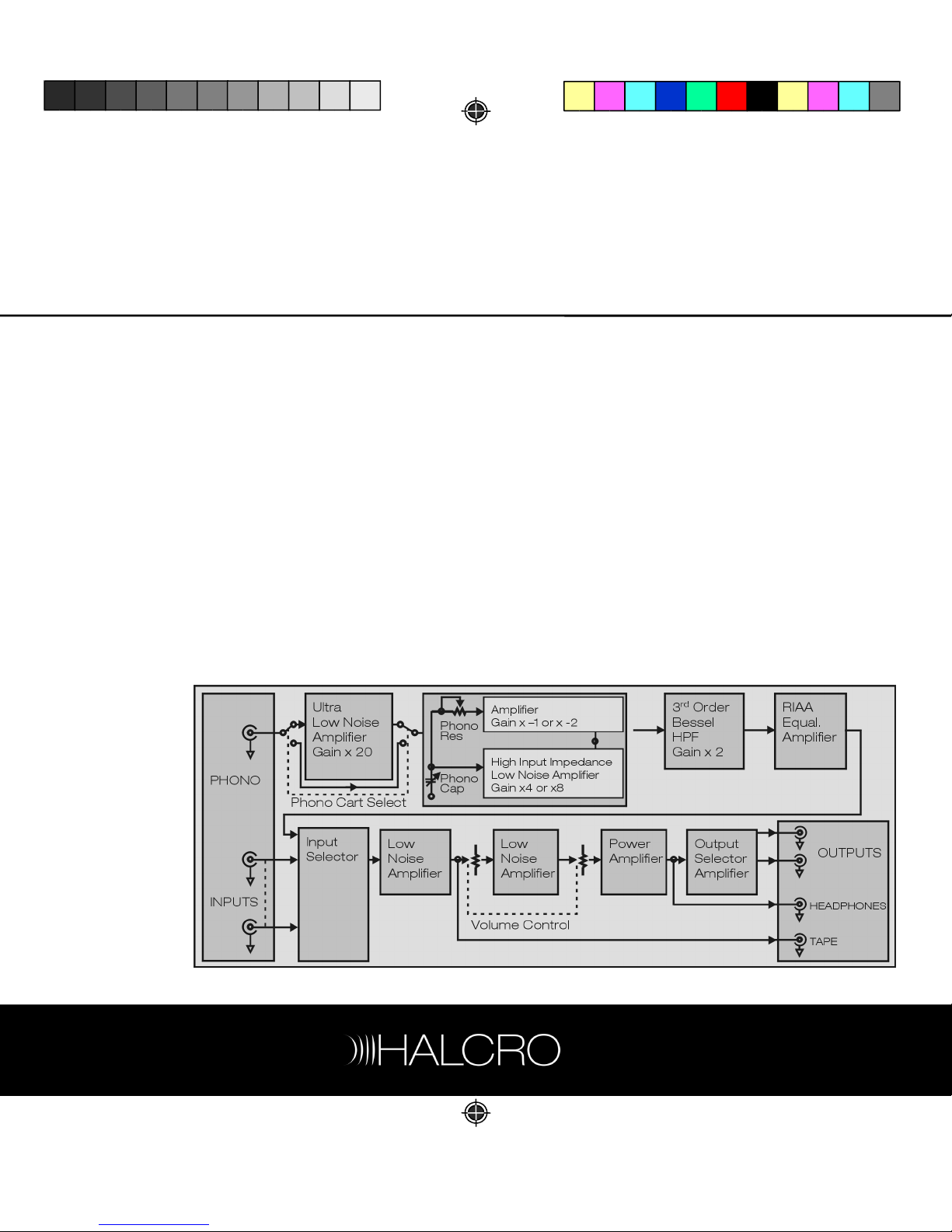
The figure below shows a functional block
diagram of the preamplifier. As can be seen,
the phono stage has four stages. Firstly, there
is an ultra low noise input stage with a gain of
x 20 for moving coil cartridges. This can be
switched out of the circuit train.
The first stage is followed by a high input
impedance (FET input) low noise amplifier with
a gain selectable to x 4 or x 8. The output of
this stage is fed to an inverting amplifier with a
gain selected to be x -2 if the high input
impedance amplifier stage gain is selected to
be x 4, or x -1 if the high input impedance
amplifier stage is selected to be x 8. (The
“minus” indicates inverting.)
The output of the inverting amplifier is
connected back to the high input impedance
amplifier stage input via a continuously variable
potentiometer. A continuously variable
capacitor is also connected to this input and
to ground.

5
The variable resistor and capacitor set the
load impedance of the high input impedance
amplifier stage and act to load moving magnet
cartridges.
This configuration forms an active load. The
variable capacitance sets the load
capacitance and the load resistance is 1/8th of
the value of the potentiometer resistance. This
configuration lowers the noise floor at high
frequency, and its attributes are described
below.
The output of the high input impedance
amplifier stage is, as well, fed to a 15Hz 3rd
order high-pass Bessel filter. This acts as a
“rumble-filter.” Following this is the RIAA
equalization stage. The RIAA equalization
adheres to the RIAA specification within
0.25 dB at all frequencies.
The output of this RIAA stage is fed to a low
noise input selector stage, which has a gain of
2. In truth, if a phono input is selected, this gain
can be set to either 1 or 2, depending upon
the gain of the selected phono input. Some
inputs are balanced inputs and one input is a
current input with a load impedance of 51
ohms, for optimal inter-connect load
matching. The equivalent input noise of the
voltage inputs is approximately
3.5 nV/sqrt (Hz), and that of the current input
is 13 pA/sqrt (Hz).
The volume control is implemented so as to
include two identical stages in series. This
minimizes output noise.

6
Audible relay noise
The dm8 and dm10 use mechanical relays in
all switching including the volume control
because they exhibit the following ideal
characteristics:
•zero ON resistance
•infinite OFF impedance
•very low OFF capacitance
•zero distortion
In contrast, the now universally popular solid-
state relays/switches exhibit none of these
ideal properties and detract from
performance. Hence, sonically, Halcro feels
that it is worth the side effect of mechanical
clicking sounds when parameters are
changed.
Microprocessor control
The excellent audio electronics are
complemented and controlled by a number of
highly integrated micro-controllers located
close to the electronics they serve. Being as
near as possible to the controlled electronics
allows short control paths and virtually
eliminates internal connectors, thereby greatly
increasing system reliability.
Each amplifier channel has its own micro-
controller; the front panel display and user
interface has another. A fourth micro-
controller, located on the rear connector
panel, co-ordinates the activity of the others.
The four micro-controllers are linked via only
four interconnections each.
A unique programming feature of the
microprocessor has been developed which
allows the user to dedicate a particular pair of
input sockets to a specific input device. This
feature provides the user with great flexibility
for connecting input devices to the
preamplifier.
The rear panel has provision to accommodate
six input devices into nine physical pairs of
input sockets. There are two pairs of
dedicated phono inputs, one pair of current
inputs, three pairs of balanced inputs and
three pairs of unbalanced inputs. Phono inputs
do not require programming as they are
permanently allocated to the phono source.

7
Industrial design
Product form
The aim when designing the dm8 and dm10
was to create a preamplifier that was
unmistakably part of the Halcro product family,
but at the same time a component that would
compliment any high-end audio system.
The preamplifier had to sit comfortably within a
contemporary domestic environment, retain
the visual signature of the Halcro family of
products, which differentiates them from
other high-end audio products, and have an
appearance that reflected the high level of
technical innovation. As with other Halcro
products, softer forms and textures are used,
all fasteners are concealed and the heat sinks
are integrated into the external form to
maintain simple, clean lines.
Whilst the unique pillar forms of the power
amplifiers have been carried through to the
preamplifier, proportions have been reworked
to allow this component to be either
freestanding or housed within a standard 19”
shelving system.
Control interface
Knobs and buttons
The volume and input selector knobs use a
unique magnetic incremental indexing
mechanism developed to provide a very
subtle and reliable indexing action. The knobs
and buttons are finished in the same soft
textural finish as the pillars.
Display
A high-resolution display was chosen in order
to provide clean simple graphics without the
rough edges associated with displays of
lesser quality. The graphic layout of the display
has been optimized to give prominence to the
functions that are viewed most often. These
include volume levels, balance and input
selection. Functions that are accessed less
often are displayed in smaller type along the
bottom of the screen. These include
stereo/mono and in or out-of-phase. The
volume levels for each channel are displayed
side-by-side so that when the levels are not
equalized the user will easily notice it.
Remote control
When designing the Halcro Remote Control,
we aimed to reflect the quality and forms of
the Halcro preamplifiers. Machined from a
solid aluminum extrusion, the remote rests
comfortably in the right hand with its minimalist
array of buttons falling within the natural
sweep of the thumb. Simple and logical to
operate, every effort has been made to keep
this product free of unnecessary complexity.

8
Mechanical design
The Halcro dm8 and dm10 can boast their
spectacularly low noise and distortion
specifications while their cases contain
inherently noisy digital circuitry, including a
switch-mode power supply, partly due to the
mechanical design of their circuit boards and
the boxes that contain them. Supports of
folded aluminum serve not only as bases to
which the electronics are anchored, but also
to shield different sections of the circuitry from
one another.
Each of the audio, panel and display, and
power supply sections is contained within its
own internal aluminum enclosure. Cables
connecting the separate sections are few and
short, minimizing both radiation and reception
of unwanted signals.

9
Installation
Ensure you have read the Important Safety
Information on page 3, before installing your
Halcro preamplifier.
If you require assistance in the unpacking and
installation of your Halcro preamplifier, please
contact your dealer.
Unpacking
oUnscrew the four knurled knobs at the
base of the container and remove the
upper part of the container by lifting
directly upwards, until it clears the top of
the preamplifier.
oRemove the plastic wrapping and foam
pieces, then lift the preamplifier from the
base of the container and remove the
plastic covering from the unit.
Please save all packaging material for later
use.
oRemove the center piece of foam in the
base of the transit case, to locate the
remote control and power cable.
oWearing the white cotton gloves provided
(to prevent marking the amplifier while
moving it in to position), move the unit to
its final location (see Positioning).
Do not connect to mains power
until all the connections are
made and checked.
Storing packaging
The packaging is custom-designed to prevent
damage from occurring during transport.
Store the packaging in a dry location.
Positioning
The Halcro dm10 preamplifier can be placed
anywhere indoors. There is no need to leave
room around the unit to allow for ventilation as
the dm10 does not generate significant
amounts of heat.
To ensure ultimate performance and to avoid
potential safety hazards, place the unit on a
firm and level surface. When placing the unit
on a shelf, be certain that the shelf and
mounting hardware can support the weight of
the product.

10
Controls and Connections
Front panel
Figure 1
1. Headphone jack
2. Remote sensor window
3. LCD information display
4. Balance control left
5. Standby/On button
6. Mute button
7. Balance control right
8. Input select control
9. Volume control
10. Phase button
11. Mono/Stereo button

11
1. Headphone jack: This jack may be used to
listen to the dm10’s output through a pair of
headphones. Ensure that the headphones
have a standard ¼” stereo plug.
2. Remote sensor window: Behind this
window is a sensor that receives infrared
signals from the remote control. Aim the
remote at this area and do not block or cover
the sensor window.
3. LCD information display: This display
delivers messages and system status to assist
you in operating the unit. See Fig 2 for a
complete breakdown on the display.
4. Balance control left: Use this button in
conjunction with Balance Control Right (Fig
1, 7) to change the relative volume for the left
and right channels. Pressing the Left button
increases the volume on the left hand channel
and decreases the volume on the right.
5. Standby/On button: The Halcro dm10 is
designed to remain in Standby mode when
not in use. This button will toggle the unit
between Standby and On.
To turn the unit off completely, use the Main
Power Switch on the rear panel.
6. Mute button: Depressing this button mutes
the output to the speakers but not the
headphones.
7. Balance control right: Use this button in
conjunction with Balance Control Left (Fig 1, 4)
to change the relative volume for the left and
right channels. Pressing the Right button
increases the volume on the right hand
channel and decreases the volume on the left.
8. Input select control: By turning this knob,
the preamplifier scrolls through all
programmed input devices (CD player, Tuner,
DVD, and so on) attached to the unit. The
corresponding selected input is displayed.
9. Volume control: Turn this knob clockwise
to increase the volume and counter-clockwise
to decrease the volume. To mute the system,
when the speakers are balanced, continue to
turn the knob counter-clockwise until the
word MUTE appears on the display, or press
the MUTE button.
10. Phase button: Depressing this button
toggles the unit between in-phase and out-of-
phase mode.
11. Mono/Stereo button: Whenever Phono is
selected, depressing this button changes the
unit between Stereo and Mono modes.

12
Front panel display
Figure 2
A
B
1. Main information display: The information
provided on this display changes depending
on what function is currently being processed.
In normal use it will display the volume of both
the left and right of the system (Fig 2, D).
When a different signal source is selected it
will appear on the main display for a few
seconds. (Fig 2, B).
C
D
2. Signal source indicator: Displays the signal
source that is currently selected.
3. Signal source location indicator: Displays
the input to which the signal source has been
connected.
4. Phase indicator: Displays whether the unit
is in- or out-of-phase.
5. Stereo indicator: Displays whether the unit
is in stereo or mono mode.

13
Rear panel
Figure 3
1. Phono capacitance selector
2. Phono resistance selector
3. Phono ground terminal
4. Phono gain switch
5. Phono cartridge selector switch
6. Phono stage inputs
7. Programmable inputs
8. Program buttons
9. Tape monitor output
10. Output sockets
11. Ground switch
12. Remote sensor window
13. Main power switch, mains socket and
fuse holder
14. Remote power amplifier control output
15. Output selector switch

14
1. and 2. Phono resistance and capacitance
selector: Allows the user to precisely match
the dm10 to the capacitance and resistance of
the phono cartridge.
3. Phono ground terminal: Ensures your
phono unit is grounded when using
unbalanced inputs.
4. Phono gain switch: Allows the user to set
the phono input x1, x2 or x4 to match the
output of the cartridge.
5. Phono cartridge selector switch: Allows the
user to choose between a moving magnet or
moving coil cartridge.
6. Phono stage inputs: Allows the user to
connect the turntable to either the Balanced
or Unbalanced inputs.
7. Programmable inputs: Provides connection
to your signal sources. It does not matter
which input each source is connected to, as
these inputs are allocated using remote
control.
8. Program buttons: Allows the inputs to be
programmed by the remote control. They will
remain illuminated once they have been
allocated – see
Connecting signal sources
on
page 16.
9. Tape monitor output: For recording direct
to tape.
10. Output sockets: Used to connect the
preamplifier to power amplifier(s).
11. Ground switch: If the dm10 is attached to a
power amplifier leave this switch on
Remote
. If
the unit is not attached to a power amplifier
and the user is using the headphones, switch
to
Local.
12. Remote sensor window: Behind this
window is a sensor that receives infrared
signals from the remote control. Aim the
remote at this area and do not block or cover
this sensor window.
13. Main power switch, socket and fuse
holder: Once the dm10 has been
programmed, the main power switch can be
left on and the dm10 left in Standby when not
in use. If the main power switch is turned off,
all programming is stored in memory.
14. Remote power amplifier control output:
Connect a cable from this output to the power
amplifier(s) and the dm10 will switch the power
amplifier(s) between Standby and On.
15. Output selector switch: Allows the user to
select the type of output required, Balanced,
Unbalanced or Current. see
dm10 outputs
on
page 16
.

15
Remote control
Figure 4
1. Volume buttons
2. Mute button
3. Standby/On button
4. Signal source buttons
5. Function button
1. Volume buttons: For volume control and
also used in conjunction with the function
button for various function selections.
2. Mute button: Press to mute sound to the
loudspeakers, press again to reactivate the
sound.
3. Standby/On button: Press to switch the
system between Standby and On.
4. Signal source buttons: Press to select any
one of six signal sources on the dm10.
5. Function button: Press to choose the
following functions: balance between the
speakers, in-phase and out-of-phase and
stereo/mono. See relevant operating
instructions for full details.
Remote control batteries
To replace the batteries, remove the battery
cover from the rear of the remote control, and
insert the three supplied AAA batteries into the
unit (ensure that the polarity is correct). Refit
the battery cover.
If the remote control will not be used for a
period longer than one month, remove the
batteries.

16
r
dm10 outputs
The balanced voltage outputs or current-
mode outputs are most desirable for
minimizing earth loop generated mains hum
and ripple, or high frequency interference if
these are a problem.
Power Amplifiers with current-mode inputs
are rare and are most likely to have an RCA
input socket. The advantages of this are:
•earth loop generated mains hum and
ripple are minimized
•cable, plug and socket-generated
interference are minimized (from poor
connections, which may be affected by
sound vibration for example).
The unbalanced voltage output is quite
satisfactory as long as earth loop generated
mains hum and ripple are not a problem.
(They should not be a problem unless the
source equipment is poorly designed.)
Connecting signal sources
As a safety precaution please ensure that the
unit is not connected to the mains power
while connecting signal sources.
When you initially receive your preamplifier all
the inputs are de-allocated.
If you are changing your signal source units,
de-allocate the input source first – see
De-
allocating P ogram buttons
on page 20.
Connect all signal source units (such as a CD
player) to the terminals (Fig 3, 7) at the rear of
the preamplifier, making a note of which input
each signal source unit is connected to.
Connecting home theater
processor
As a safety precaution please ensure that the
unit is not connected to the mains power
while connecting a Home Theater Processor
(HTP).
Connect your HTP to any of the
programmable inputs at the rear of the
preamplifier.
Program the preamplifier to the unit, using
Source setup
on page 20. (We recommend
you use the DVD function.)
To set the preamplifier to operate with zero
gain, adjust both volume channels to 0.0 dB.
The preamplifier will then have no effect on
the volume. You will now be able to control
the volume of your system by using your HTP
volume control.

17
Connecting to a power amplifier
Each dm10 has:
•two pairs of unbalanced current outputs
(use one pair for un-bridged power
amplifiers, use both for driving bridged
amplifiers)
•two pairs of unbalanced voltage outputs
•two pairs of balanced voltage outputs for
power amplifiers.
Select the method in which you wish to run
your power amplifiers, and connect the units
using high quality cables.
Outputs are color-coded:
•Positive + right channel (red bezel)
•Negative - left channel (white bezel)
The dm10 will control power amplifiers from
balanced and unbalanced voltage sources, as
well as an unbalanced current source. The
dm10 will also control power amplifiers in
bridged pair configuration. Custom-made
cables are required to run bridged power
amplifiers from the balanced Voltage Output
Remote power amplifier control
output
The dm10 has a remote power amplifier
control output (Fig 3,14), which will remotely
switch the Halcro amplifiers from Standby to
On. Cables can be purchased through Halcro
for details please E-mail us at:
service@halcro.com

18
Connecting phono stage
Connect your turntable to the appropriate
input connectors (Fig 3, 6) located on the left
of the rear panel. The dm10 has the option of
connecting turntables with either balanced or
unbalanced outputs (only one turntable
should be connected at any time).
When using unbalanced inputs ensure that
the turntable is grounded through the
preamplifier’s Ground Terminal (Fig 3, 3).
Select either the moving magnet or moving
coil cartridge, (Fig 3, 5) to match your
turntable.
The dm10 has three gain settings for the
phono input: x1, x2 and x4 (Fig 3, 4). This
allows the user to match the preamplifier to
the output of the cartridge. Select appropriate
gain level.
The dm10 can be precisely matched to the
capacitance and resistance of the moving
magnet cartridge by adjusting the
corresponding knobs at the rear of the unit
(Fig 3, 1 and 2).
The phono button on the remote control is
permanently allocated.
Connect the mains supply
cable
Plug the main power cable into the main
power socket on the rear of the dm10
(Fig 3 13).
Bridging
The dm10 will control bridged power
amplifiers. A bridging kit can be purchased
through Halcro. For details please E-mail us at:
service@halcro.com
Break-in period
The dm10 electronic break-in period is
completed at the factory. A further break-in
period is not required.

19
Programmable input selections
The dm10 has seven available pairs of
programmable input connectors:
•three unbalanced voltage inputs
•three balanced voltage inputs
•one unbalanced current input.
All inputs that have a signal source connected
must be programmed by the remote control.
Any input can be programmed to connect any
source and each button on the remote
control can have only one signal source
programmed to it at any time.
The Phono input is pre-allocated to the phono
'source' and cannot be changed.
Input
Modes
Required output source
impedance
Input
socket Input impedance
Balanced voltage input XLR: Low source impedance XLR 10 kohms +
10 kohms
Unbalanced voltage input RCA: Low source impedance RCA 10 kohms
Unbalanced current input RCA: Infinite source impedance RCA 50 ohms
Other manuals for DM10
1
Table of contents
Other Halcro Amplifier manuals

Halcro
Halcro SSP100 User manual

Halcro
Halcro MC70 User manual

Halcro
Halcro SSP100 User manual

Halcro
Halcro DM10 User manual

Halcro
Halcro DM88 User manual

Halcro
Halcro MC20 Quick start guide

Halcro
Halcro DM8 User manual

Halcro
Halcro Eclipse mono User manual

Halcro
Halcro MC30 Quick start guide

Halcro
Halcro MC50 Quick start guide