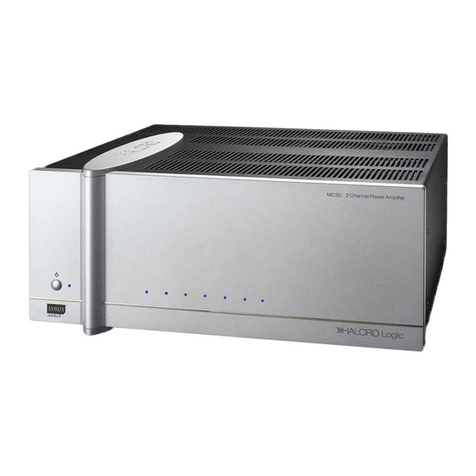
Halcro DM88 User manual

Monoblock Power Amplifier
Owner’s Manual
www.halcro.com
dm88
dm78

1
Contents
Introduction................................................2
Important Safety Information...................3
Symbols ......................................................... 3
Electrical safety............................................. 4
Protection from fluids .................................. 4
Service warnings .......................................... 5
Protection from overheating ...................... 5
Lifting or moving........................................... 6
Wiring to the loudspeaker terminals to
Class 2 wiring (US wiring regulations) ....... 6
Additional Important Safety Instructions
for US ..........................................................7
Interference Warning - US FCC
Regulations ................................................8
For Consumers within the European
Union:..........................................................9
Installation................................................. 10
Unpacking ....................................................10
Storing packaging .......................................10
Positioning....................................................10
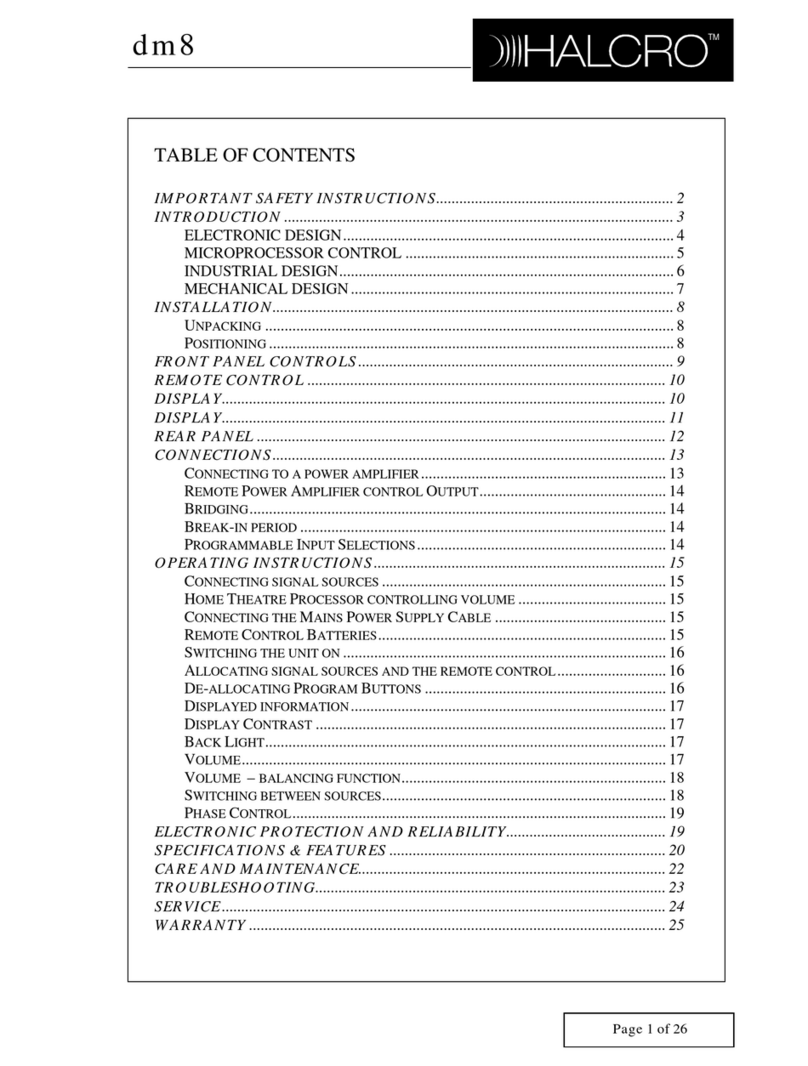
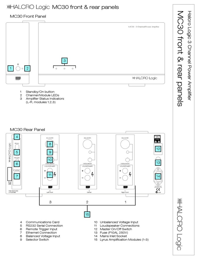
Controls and Connections......................11
Connecting the loudspeakers ...................11
Connecting the external ground ...............11
Connecting the mains supply cable..........11
Break-in period.............................................11
dm78 Inputs .................................................12
dm88 Inputs.................................................13
Operation ................................................. 14
Electronic Protection and Reliability ..... 15
Components................................................15
Output Current Limiting ..........................16
Output transistor protection...................... 17
Unusual output conditions.........................18
Power supply output current limiting .......18
Internal power supply protection.............. 18
Mains transient overload protection ........18
Input overload protection ..........................18
Amplifier inter-stage protection ................18
dm78 Specifications................................19
dm88 Specifications ...............................21
Care and Maintenance.......................... 24
Cleaning....................................................... 24
Troubleshooting...................................... 25
Service and Warranty Information ....... 26
Overview ..................................................... 26
Product warranty ....................................... 26
Exclusions to the warranty ....................... 26
Transferability.............................................. 27
Warranty verification .................................. 27
Warranty registration ................................. 27
If service is required ................................... 27
Transportation of products....................... 28
Freight damage claims.............................. 28
If you have moved ..................................... 28
Thank you for choosing Halcro!............... 28
2
Introduction
Congratulations on purchasing the Halcro
dm78 or dm88 monoblock amplifiers.
Halcro designs and manufactures the only
"Super Fidelity" amplifiers in the world. This
"Super Fidelity" amplifier reproduces with
better than 99.9997% purity of all tones
across the entire audio range.
The concept behind the electronic design was
to create an amplifier that did not color the
sound with its own electronic characteristics
— to recreate the original sound as it was at
the time of recording.
Please enjoy the Halcro audio experience.
Halcro has enjoyed creating perfect audio
reproduction for the world's music
connoisseurs.
If you desire to contact Halcro to give us
feedback on your purchase or for general
enquiries;
Please feel free to contact us via:
Telephone: + 61 8 8238 0807
Facsimile: + 61 8 8238 0852

3
Important Safety Information
Symbols
The following symbols are used on this
equipment:
The lightning flash with
arrowhead symbol, within an
equilateral triangle, is intended to
alert the user to the presence of
uninsulated ‘hazardous voltage’
that may be of sufficient
magnitude to constitute a risk of
electric shock to a person if
exposed or contacted.
The exclamation point within an
equilateral triangle is intended to
alert the user to the presence of
important operating and
maintenance (servicing)
instructions in the following
pages.
The ‘CE’ symbol indicates
compliance of this device with
the relevant directives of the
European community including
the EMC (Electromagnetic
Compatibility) and LVD (Low
Voltage Directive) standards.
Warning of electrical shock
hazard. Do not open cover
(or back). There are no user
serviceable parts inside.
Refer servicing to qualified
service personnel.
120lb
This symbol is to indicate
that the unit is heavy and
that precautions are
required when lifting or
moving the unit.

4
Electrical safety
WARNING: This product must
always be connected to a
mains socket outlet with a
protective earth connection.
Only use a suitable approved mains cord
complying with European individual country
requirements in the CE Low Voltage Directive
Scheme.
DANGER: Do not
open the cover or
back, or remove any
panels, or try to
modify or repair the
dm78/88. Opening
the dm78/88 may
expose you to
dangerous voltages
and will void the
warranty.
WARNING: The Standby/On
mode switch does not
disconnect the unit from the
mains power.
To disconnect the unit from the
mains switch off the unit at the
mains socket outlet and
withdraw the mains plug from
the socket outlet
,
.
The unit should be installed in a position where
the mains plug is easily accessible. Disconnect
the unit from the mains if it is to be left unused
for a long period.
WARNING: No naked flame
sources, such as lighted
candles, should be placed on
the unit.
If naked flame sources tip over
they could result in a fire.
Protection from fluids
The Halcro Logic dm78/88 units are designed
for indoor use only and are not protected
against liquids. They must not be exposed to
dripping or splashing and no objects filled with
liquids, such as vases, should be placed on
them.
If liquid is accidentally spilled on the device,
immediately disconnect the unit from the
mains. Allow sufficient time for complete
evaporation before using the dm78/88 again.
If the liquid is anything other than water, do not
use the device before a qualified service
technician has examined it.

5
Cleaning may be performed with a slightly
damp cloth that has been wrung until nearly
dry. Refer to the section on
Cleaning
on
page 24.
WARNING: To reduce the risk
of fire or electric shock, do not
expose this equipment to rain
or moisture.
Do not allow liquids to enter
the unit or contact electrical
terminals.
Service warnings
All compartments are sealed at the factory. If
the seals are broken, the warranty will be void
and all service costs will be charged to the
owner.
DANGER: Contains no user
serviceable parts. Do not
attempt to open any of the
dm78/88 compartments as
this may expose you to
dangerous voltages and will
void the warranty.
Requires F 10 A L 250 V fuse for continued
protection against the risk of fire. Never
bypass or use any other type of fuse. The fuse
is located on the bottom of the lower panel of
the power amplifier (13).
WARNING: Always replace the
fuse with the same type and
rating as specified: F 10
A L
250 V.
DANGER: Always disconnect
the unit from the mains before
touching the loudspeaker
terminals or replacing the fuse.
Protection from overheating
The dm78/88 generates a certain amount of
heat and requires ventilation. Slots and
ventilation holes are provided for ventilation
purposes, and to ensure reliable operation of
the product. To prevent fire hazards, these
openings must never be blocked or covered.
Follow the precautions listed below. If these
precautions are not followed, overheating or
failure may result. Overheating also shortens
the working life of all components.
•do not block the ventilation slots in the
sides of the unit with any object, including
paper, cloths or curtains
•avoid placing the unit in a built-in
installation place such as a bookcase or a
rack unless you can provide proper
ventilation
•do not operate the unit inside a cabinet
unless it has adequate ventilation (such as
an open back panel)
•allow at least 12 in (300 mm) clearance
around the unit
WARNING: Do not obstruct
ventilation slots in the chassis.

6
Lifting or moving
120lb
WARNING: Weighs 55
kg (120
lb)
per unit. Shipping weight is 85
kg
(187
lb). Never lift the ampl ier by
yourself.
if
.
Always use two people to
unpack or move the amplifier
Always bend at the knees when
lifting. Do not strain your back.
Wiring to the loudspeaker
terminals to Class 2 wiring
(US wiring regulations)
This equipment has been classified as having
a Class 2 loudspeaker output requiring wiring
to connect the output terminals to class 2
according to the National Electrical Code.
Consult a qualified installer or electrical
contractor for further information.

7
Additional Important Safety Instructions
for US
The following instructions should be followed
by customers in the USA in addition to the
safety instructions in the rest of this chapter:
oRead these instructions.
oKeep these instructions.
oHeed all warnings.
oFollow all instructions.
oDo not use this apparatus near water.
oClean only with dry cloth or according to
the cleaning instructions.
oDo not block any ventilation openings.
oInstall in accordance with the
manufacturer’s instructions.
oDo not install near any heat sources such
as radiators, heat registers, stoves, or
other apparatus (including amplifiers) that
produce heat.
oDo not defeat the safety purpose of the
polarized or grounding-type plug.
A polarized plug has two blades, with one
wider than the other. A grounding type
plug has two blades and a third
grounding prong. The wide blade or the
third prong is provided for your safety. If
the provided plug does not fit into your
outlet, consult an electrician for
replacement of the obsolete outlet.
oProtect the power cord from being
walked on or pinched particularly at
plugs, convenience receptacles, and the
point where they exit from the apparatus.
oOnly use attachments/accessories
specified by the manufacturer.
oUnplug this apparatus during lightning
storms or when unused for long periods
of time.
oRefer all servicing to qualified service
personnel.
Servicing is required when the apparatus
has been damaged in any way, such as if
the power-supply cord or plug is
damaged, liquid has been spilled, or
objects have fallen into the apparatus, if
the apparatus has been exposed to rain
or moisture, does not operate normally,
or has been dropped.
.

8
Interference Warning - US FCC Regulations
This equipment has been tested and found to
comply with the limits for a Class B digital
device, pursuant to part 15 of the FCC Rules.
These limits are designed to provide
reasonable protection against harmful
interference in a residential installation. This
equipment generates, uses, and can radiate
radio frequency energy and, if not installed
and used in accordance with the instructions,
may cause harmful interference to radio
communications. However, there is no
guarantee that interference will not occur in a
particular installation.
If this equipment does cause harmful
interference to radio or television reception,
which can be determined by turning the
equipment off and on, the user is encouraged
to try to correct the interference by one or
more of the following measures:
oIncrease the separation between the
equipment and receiver.
oConnect the equipment into an outlet on
a circuit different from that to which the
amplifier is connected.
oConsult the dealer or an experienced
radio/TV technician for help.
Changes or modifications not expressly
approved by Halcro could void the user's
authority to operate the equipment.

9
For Consumers within the European Union:
The following instructions should be followed
by customers in the EU in addition to the
safety instructions in the rest of this chapter:
oDo not dispose of this equipment in
general household waste or unsorted
municipal waste.
The crossed out wheeled bin indicated
on this equipment is an indicator that this
unit should not be disposed of in general
household waste, but recycled in
compliance with local government
regulations or environmental
requirements.
oPlease dispose of this equipment via a
recycling service or centre, or by
returning the unit to the local
Minelab/Halcro distributor.
This will enable the equipment to
be disposed of in an environmentally safe
manner.
oDisposal of unwanted waste electronic
equipment in landfilled waste may
contribute to adverse long term
environmental effects due to the leaching
of contaminating and/or toxic substances
contained within some electronic
equipment.

10
Installation
Ensure you have read the Important Safety
Information on page 3, before installing your
Halcro amplifier.
Do not connec to
mains power un il all the
connections are made
and checked.
t
t
If you require assistance in the unpacking and
installation of your Halcro amplifier, please
contact your dealer.
NOTE: When l ting the unit,
always use two people.
if
The unit must be lifted by placing
your hands under the middle of
the bottom compartment. Do
not lift the unit under the top
compartment.
Unpacking
oUnscrew the four knurled knobs at the
base of the container, and then remove
the upper part of the container by lifting
directly upwards until it clears the top of
the amplifier.
oWith an assistant, remove the plastic
wrapping and foam pieces, then lift the
amplifier from the base of the container.
oRemove the plastic covering from the
unit.
oWearing the white cotton gloves
provided (to prevent marking the
amplifier while moving it into place) move
the unit to its final location (see
Positioning).
Storing packaging
The packaging is custom designed to prevent
damage from occurring during transport.
Store the packaging in a dry location.
Positioning
We suggest that the Halcro amplifiers be
positioned as near to your loudspeakers as
practical. This will reduce the length of the
loudspeaker cable required. The sides of the
unit house the heat sinks that are used to
dissipate heat. The airflow to these should not
be interrupted. Ensure there is at least
12 inches (300 mm) clearance around the
unit.

11
Controls and Connections
Connecting the loudspeakers
The dm78 and dm88 have four loudspeaker
terminals each:
•2 x positive + (red bezel)
•2 x negative - (black bezel)
All of the pure copper connections are finished
with the highest-grade gold plating.
oEnsure the positive terminal of the
amplifier connects to the positive terminal
of the loudspeaker to ensure correct
phasing of the audio signal.
The loudspeaker terminals will accept
spade or hook terminals. Only fully
insulated terminals should be used.
oEnsure the loudspeaker terminals are
securely tightened, but do not over
tighten or you may damage the terminals.
oWhen connecting loudspeaker cables
always ensure the conductive surfaces
are not touching each other.
DO NOT SHORT-CIRCUIT THE
TERMINALS.
Connecting the external
ground
The dm78 and dm88 are equipped with a
separate ground terminal, which may be used
to reduce hum and ripple in some
circumstances.
T
here may be high vol ages
present at the loudspeaker
terminals which may present an
electric shock hazard i touched.
Always ensure the unit is
switched to OFF or Standby
mode when connecting or
disconnecting loudspeakers.
t
,
f
The ground terminal has a green bezel, and is
located either under the power supply (dm88)
or on the connector panel on the rear of the
unit (dm78).
Connecting the mains supply
cable
Connect the mains plug into the socket at the
rear, on the base of the bottom compartment,
which houses the power supply. Ensure the
cable exits to the rear of the unit.
Continue to read the following pages before
connecting to the mains outlet.
Bridging
You may bridge the Halcro dm78 and dm88
amplifiers, for details please E-mail us at:
service@halcro.com
Break-in period
The dm78 and dm88 electronic break-in
period is completed at the factory. A further
break-in period is not required.

12
dm78 Inputs
The dm78 has three switch selectable inputs,
each having an associated input socket. Both
the input sockets and switch are mounted on
the top rear panel, and the switch must be
operator set to indicate which input is
required. The table below lists the properties
of these three inputs.
The balanced voltage input or current-mode
input are most desirable for minimizing earth
loop generated mains hum and ripple, or high
frequency interference. Earth loop generated
mains hum and ripple, or high frequency
interference should not be a problem unless
the source equipment is poorly designed.
Sources with current-mode outputs are rare
and are most likely to have an RCA output
socket. The advantages of this source are
that:
Earth loop generated mains hum and ripple
are minimized, and cable, plug and socket
generated interference is minimized (from
poor connections which may be affected by
sound vibration for example).
The unbalanced input is quite satisfactory so
long as earth loop generated mains hum and
ripple are not a problem.
The input sockets may have active sources
simultaneously connected to them. The
selector switch selects the input to be
amplified.
Input styles Required output source
impedance
Input
socket Input impedance
Balanced voltage input Low impedance. Standard
preamplifier or CD player for
example.
XLR 100 kohms + 100 kohms
Unbalanced voltage
input
Low impedance. Standard
preamplifier or CD player for
example.
RCA 100 kohms
Current-mode input Very high impedance; “infinite.” RCA 60 ohms

13
dm88 Inputs
The dm88 has four switch selectable inputs,
each having an associated input socket. The
input sockets and switch are mounted on the
top rear panel, and the switch must be
operator set to indicate which input is
required. The table below lists the properties
of these four inputs.
The balanced voltage input or current-mode
input are most desirable for minimizing earth
loop generated mains hum and ripple, or high
frequency interference. Earth loop generated
mains hum and ripple, or high frequency
interference should not be a problem unless
the source equipment is poorly designed.
Sources with current-mode outputs are rare
and are most likely to have an RCA output
socket. The advantages of this source are
that:
Earth loop generated mains hum and ripple
are minimized, and cable, plug and socket
generated interference is minimized (from
poor connections which may be affected by
sound vibration for example).
The unbalanced input is quite satisfactory so
long as earth loop generated mains hum and
ripple are not a problem.
The minimal path input will result in the most
pure sound; unless as above, earth loop
generated mains hum and ripple is a problem.
The input sockets may have active sources
simultaneously connected to them. The
selector switch selects the input to be
amplified.
Input styles Required output source
impedance
Input
socket Input impedance
Balanced voltage input Low impedance. Standard
preamplifier or CD player for
example.
XLR 100 kohms + 100 kohms
Unbalanced voltage
input
Low impedance. Standard
preamplifier or CD player for
example.
RCA 100 kohms
Minimal path voltage
input
Low impedance. Standard
preamplifier or CD player for
example.
RCA 660 ohms
Current-mode input Very high impedance; “infinite.” RCA 60 ohms

14
Operation
All or some of the input sockets may have
active sources simultaneously connected to
them. The selector switch selects the input to
be amplified.
oOnce the external cables are connected
to the unit, ensure the master ON/OFF
switch is in the OFF position.
The master ON/OFF switch is on the
base of the lower compartment, near the
mains socket on the unit. You will have to
kneel on the floor at the back of the unit
to access the switch.
oPlug the mains plug into a mains outlet.
oSwitch the master ON/OFF switch to ON.
The LEDs on the front and rear of the
amplifier will glow red. This indicates the
unit is in Standby mode. In this mode a
small current is drawn from the mains
supply, but the unit will not drive the
loudspeakers.
oPress the mode switch once to switch
between Standby and ON modes.
The mode switch is a small pressure
switch accessed when standing at the
front of the unit. It is located under the
bottom lip of the top compartment.
When the amplifier has been switched to ON,
the LEDs on the front and rear will glow green.
The amplifier is now ready to drive your
loudspeakers.
It is recommended that the unit be switched
to Standby when not in use.
It is safer to turn the mains power off when not
using the dm78 or dm88 monoblock
amplifiers for extended periods. However the
amplifier may be left on in the Standby mode
for periods between active use. If you wish to
turn the mains power off, the amplifier has a
minimal warm up period.

15
Electronic Protection and Reliability
Electronic protection circuitry and amplifier
reliability, alas, is an area sadly neglected by
many high-end audio amplifier designers.
Halcro has paid a great deal of attention to this
area.
Components
Our components are selected not only for
performance but reliability as well, for
example:
•all Halcro electrolytic capacitors are rated
at a minimum of 105ºC instead of the
usual 85ºC rating
The operational life of electrolytic
capacitors is severely shortened at
temperatures near the maximum
temperature rating. This is shown in the
table below.
•all Halcro integrated circuits are at least
“industrial grade” rather than the usual
“commercial grade”
Industrial grade components are rated at
least from –40ºC to +85ºC whereas
commercial grade components are only
rated from 0 to 70ºC. In addition, the
electronic specifications of industrial
grade components are superior to
commercial grade.
Considering that most amplifiers run at
significantly elevated temperatures, it can be
seen from the table below that the Halcro high
temperature rated capacitors are highly
advantageous compared to the standard
85ºC rated devices.
Electrolytic capacitor
temperature rating
Mean lifetime at 40ºC
Mean lifetime
at 85ºC
Mean lifetime
at 105ºC
85ºC (most commonly used)
50,000 hours
2,000 hours 0 hours
105ºC (used in Halcro
amplifiers)
180,000 hours
8,000 hours 2,000 hours
Typical data from a highly respected manufacturer

16
Output Current Limiting
In terms of maximum available output current,
there are basically three amplifier type options:
•an amplifier with a reasonable limit placed
on the maximum available output current
•an amplifier with no limit placed on the
maximum available output current, which
will either blow a fuse or self destruct if
excessive current is drawn, for example
through a dead short
•an amplifier with a very high limit placed
on the maximum available output current,
but designed not to blow a fuse if this
very high current is drawn
If the maximum current drawn from an
amplifier with maximum available current
limiting is reached under very loud music
conditions (the first and third amplifier
types above), highly obvious “cracking”
overload sounds may be heard. Note that this
overload sound may also occur if a
loudspeaker overloads or if any amplifier
suffers voltage overload.
There is an expectation in the audiophile
electronic industry that a high end amplifier
should be capable of delivering exactly double
the output current for a halving of the
loudspeaker impedance (down to 1 ohm) at
the maximum output voltage that the amplifier
can produce.
This requires an amplifier of the second and
third type above. The table below lists an
example of an amplifier rated at 150 watts
output into 8 ohms.
Loudspeaker
load impedance Output power Peak output
voltage
r.m.s. output
current
Peak output
current
8 ohms 150 W 49 V 4.33 A 6.12 A
4 ohms 300 W 49 V 8.66 A 12.25 A
2 ohms 600 W 49 V 17.32 A 24.5 A
1 ohm 1200 W 49 V 34.64 A 49.0 A

17
If the loudspeaker cable is inadvertently
shorted out, these sorts of currents are quite
capable of causing some cables to catch fire.
We know of one such instance with an
amplifier rated according to the table!
As we do not wish to set your house on fire
we have limited the peak output current to
15 A.
One also has to question the belief that an
amplifier should be capable of such
unreasonably high output currents. Consider
the following facts:
•most loudspeakers have impedances of
4 ohms (not 1 or 2 ohms)
•all valve amplifiers are output current
limited, and yet the industry does not
consider this a problem, which is
inconsistent with the belief that maximum
available current limiting is a problem
•all well designed loudspeakers have
impedances that do not deviate
excessively from their nominal
impedances and hence no excessively
high currents are required anyway
•if indeed a 4 or 8 ohm loudspeaker does
have an impedance of 1 ohm at a
particular frequency, one must wonder
where the heat generated is dissipated if
this load is predominantly resistive or why
the coupling is so poor if this load is
predominantly reactive
Hence we believe that these excessively high
output currents are:
•not required for well designed
loudspeakers
•highly dangerous
Many people have listened to maximum
available current limited amplifiers played
through different loudspeakers without
encountering any current limiting problems
that is, obvious “cracking” sounds at very loud
listening levels, except for loudspeaker or
voltage overloads which are independent of
current limiting.
Output transistor protection
Halcro uniquely incorporates circuitry that
accurately calculates the mean power
dissipated in the power output transistors
(power FETs). Another calculating circuit then
may reduce the maximum available output
current according to the heat-sink
temperature and calculated average
dissipated power in the transistors. The higher
the heat-sink temperature, and the higher the
mean power dissipated in the output
transistors, the greater this reduction. This will
only occur at very high heat sink temperatures
and very high mean output powers.

18
Unusual output conditions
The vast majority of amplifier faults show up as
high positive or negative DC output voltages.
An independent circuit in the Halcro amplifiers
senses any unreasonable DC. output voltage
and switches the amplifier off if this occurs.
Likewise, if any excessive output current flows
for an extended length of time, this also
implies a fault and an independent circuit
measures this and will shut down the amplifier.
Power supply output current
limiting
To further reduce the possibility of fault
conditions causing substantial damage, the
power supply is limited in its maximum
available average output current. Note that
this level is higher than the amplifier’s normal
current limiting conditions. The power supply
limit will only cut in under fault conditions.
Internal power supply
protection
There are numerous power supply protection
circuits, for example:
•two independent over temperature cut
outs
•two independent master clock fault
sensing circuits
•all power supplies, including those for
“housekeeping” Standby, active power
factor correction and switch mode power
etc check for under/over voltage and
over current conditions
•the small signal power supplies have
transient diode over-voltage protection.
Mains transient overload
protection
The mains input is protected against all but the
most severe mains input transients. Three
independent circuits achieve this: two surge
absorbers and high energy inductive filtering.
Input overload protection
The inputs have over-voltage protection
circuits, which will handle most typical input
overloads.
Amplifier inter-stage
protection
In addition within the amplifier stages, there
are more than a dozen protection circuits.

19
dm78 Specifications
Power
Power output into 4 ohms resistive > 400 W.
Power output into 8 ohms resistive > 225 W.
Distortion (Footnote 1)
At full power output, all harmonic distortion
orders
THD <-120 dB (<1000 parts per billion) up to
20 kHz (100 kHz B.W.) at 400 W into 4 ohms.
THD @ 1 kHz <-134 dB (<200 parts per billion).
For sum of 19 and 20 kHz tones, each
delivering 100 W into 4 ohms = peak power
400 W, intermodulation products each
<-120 dB relative to output.
SMPTE-IM intermodulation products each
<-120 dB relative to output.
Inputs
There are three input modes:
•an unbalanced voltage mode input with
an impedance of 100 kohms
•a balanced voltage mode input with an
impedance of 100 kohms + 100 kohms
•a current-mode input with a 60 ohm input
impedance to minimize cable reflections
(to be fed from an infinite impedance
current source)
The voltage gain of the balanced and
unbalanced inputs is 60 V/V. The gain of the
current mode is 9 V/mA.
Noise
The equivalent input noise at the input is
5 nV/sqrt(Hz) for the voltage modes and
6 pA/sqrt(Hz) for the current mode.
Slew rate limit
Maximum slew rate for both small signal and
maximum output voltage is 100V/µs, (which is
equivalent to a maximum output voltage at
approximately 250 kHz.)
Power supply (Footnote 2)
Active power factor correction minimizes
mains current harmonic distortion
•operates at all voltages from 85 to 270 V
r.m.s., 45-65 Hz, without any internal or
external switches
•less than 100 parts per million mains hum
and ripple on the amplifier power rails
•conforms with PFC and EU emission
standards set for 2002
Overload (Footnote 3)
Recovery from hard overload at 20 kHz into
4 ohms is 1 µs.
This manual suits for next models
1
Table of contents
Other Halcro Amplifier manuals

Halcro
Halcro SSP100 User manual

Halcro
Halcro MC30 User manual

Halcro
Halcro MC70 User manual

Halcro
Halcro DM8 User manual

Halcro
Halcro Eclipse stereo User manual

Halcro
Halcro MC70 User manual

Halcro
Halcro SSP100 User manual

Halcro
Halcro MC50 Quick start guide

Halcro
Halcro DM8 User manual

Halcro
Halcro DM10 User manual
Popular Amplifier manuals by other brands

Peavey
Peavey CLASSIC Series owner's manual

Sony
Sony XM-754HX Operating Instructions (English Service manual

Clifton LAboratories
Clifton LAboratories Z10042AV Assembly and operation manual

Takstar
Takstar E128 user manual

ADS
ADS ADS120D Plus Installation & operation guide

Hogtunes
Hogtunes WILD BOAR AUDIO WBA 600.4 installation manual