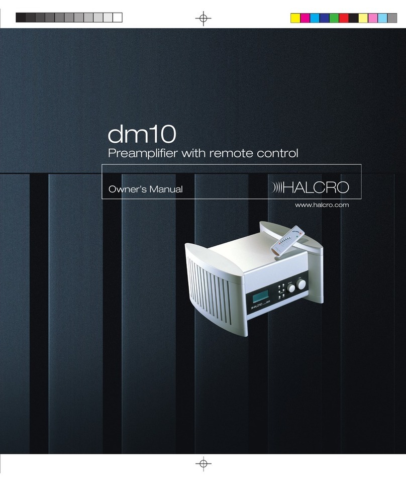
Halcro Eclipse stereo User manual


1
Contents
Introduction.......................................................2
Important Safety Information ............................3
Symbols...................................................................3
Electrical safety .......................................................4
Protection from fluids.............................................5
Service warnings .....................................................5
Protection from overheating ..................................6
Lifting or moving .....................................................6
Wiring to the Loudspeaker Terminals to Class 2
Wiring (US Wiring Regulations).........................6
Additional Important Safety Instructions for the
USA ....................................................................7
Interference warning - US FCC Regulations ........8
For Consumers within the European Union........9
Unpacking ........................................................10
Controls and Connections ................................12
Diagrams ...............................................................12
Eclipse stereo inputs .............................................14
Minimal Path Input ...............................................15
Setup................................................................16
Operation.........................................................18
Electronic Protection and Reliability................ 19
Output Current Limiting .................................. 20
Output transistor protection ................................ 21
Unusual output conditions ................................... 22
Power supply output current limiting................... 22
Internal power supply protection......................... 22
Mains transient overload protection.................... 22
Input overload protection..................................... 22
Amplifier inter-stage protection ........................... 22
Eclipse stereo Specifications............................ 23
Care and Maintenance .................................... 26
Troubleshooting .............................................. 27
Service and Warranty Information .................. 28
Overview............................................................... 28
Product warranty.................................................. 28
If service is required.............................................. 29
Transportation of products................................... 30
Thank you for choosing Halcro! ....................... 31
2
Introduction
Congratulations –You have purchased one of the
very finest audio components ever made. This bold
statement is not only measurable, but immediately
apparent from the very first note.
Halcro designs and manufactures the only Super
Fidelity amplifiers in the world. This Super Fidelity
amplifier reproduces with better than 99.9997%
purity of all tones across the entire audio range.
The concept behind the electronic design was to
create an amplifier that did not color the sound with
its own electronic characteristics —to recreate the
original sound as it was at the time of recording.
Please enjoy the Halcro audio experience.
Halcro has enjoyed creating perfect audio
reproduction for the world's music connoisseurs.
To contact Halcro with feedback on your purchase or
for general enquiries please feel free to contact us
via:
Telephone: + 61 8 8390 1673

3
Important Safety Information
Symbols
The following symbols are used on this equipment:
The lightning flash with arrowhead
symbol, within an equilateral
triangle, is intended to alert the
user to the presence of
uninsulated ‘hazardous voltage’
that may be of sufficient
magnitude to constitute a risk of
electric shock to a person if
exposed or contacted.
The exclamation point within an
equilateral triangle is intended to
alert the user to the presence of
important operating and
maintenance (servicing)
instructions in the following pages.
The ‘CE’ symbol indicates
compliance of this device with the
relevant directives of the
European community including
the EMC (Electromagnetic
Compatibility) and LVD (Low
Voltage Directive) standards.
Warning of electrical shock
hazard. Do not open cover
(or back). There are no user
serviceable parts inside.
Refer servicing to qualified
service personnel.
This symbol is to indicate
that the unit is heavy and
that precautions are
required when lifting or
moving the unit.

4
Electrical safety
WARNING: This product must
always be connected to a mains
socket outlet with a protective
earth connection.
Only use a suitable approved mains cord complying
with European individual country requirements in
the CE Low Voltage Directive Scheme.
DANGER: Do not open
the cover or back, or
remove any panels, or try
to modify or repair the
Eclipse. Opening the
Eclipse may expose you
to dangerous voltages
and will void the
warranty.
WARNING: The Standby/On mode
switch does not disconnect the unit
from the mains power.
To disconnect the unit from the
mains, switch off the unit at the
mains socket outlet and withdraw
the mains plug from the socket
outlet.
The unit should be installed in a position where the
mains plug is easily accessible. Disconnect the unit
from the mains if it is to be left unused for a long
period.
WARNING: No naked flame sources,
such as lighted candles, should be
placed on the unit.
If naked flame sources tip over they
could result in a fire.

5
Protection from fluids
The Halcro Eclipse amplifiers are designed for indoor
use only and are not protected against liquids. They
must not be exposed to dripping or splashing and no
objects filled with liquids, such as vases, should be
placed on them.
If liquid is accidentally spilled on the device,
immediately disconnect the unit from the mains.
Allow sufficient time for complete evaporation
before using the Eclipse again. If the liquid is
anything other than water, do not use the device
before a qualified service technician has examined it.
Cleaning may be performed with a slightly damp
cloth that has been wrung until nearly dry. Refer to
the section Cleaning on page 26.
WARNING: To reduce the risk of
fire or electric shock, do not
expose this equipment to rain or
moisture.
Do not allow liquids to enter the
unit or contact electrical
terminals.
Service warnings
All compartments are sealed at the factory. If the
seals are broken, the warranty will be void and all
service costs will be charged to the owner.
DANGER: Contains no user
serviceable parts. Do not attempt
to open any of the Eclipse
compartments as this may
expose you to dangerous voltages
and will void the warranty.
Requires an appropriate fuse for continued
protection against the risk of fire (F 10A L 250V or F
15A L 110V). Never bypass or use any other type of
fuse. The fuse is located on the bottom of the lower
panel of the power supply compartment (p13, fig C,
7).
WARNING: Always replace the
fuse with the same type and
rating as specified: F 10A L 250V
or F 15A L 110V as appropriate.
Always disconnect the unit from
the mains before touching the
loudspeaker terminals or
replacing the fuse.

6
Protection from overheating
The Eclipse generates a certain amount of heat and
requires ventilation. Slots and ventilation holes are
provided for ventilation purposes, and to ensure
reliable operation of the product. To prevent fire
hazards, these openings must never be blocked or
covered.
Follow the precautions listed below. If these
precautions are not followed, overheating or failure
may result. Overheating also shortens the working
life of all components.
oDo not block the ventilation slots in the sides
of the unit with any object, including paper,
cloths or curtains
oAvoid placing the unit in a built-in installation
place such as a bookcase or a rack unless you
can provide proper ventilation
oDo not operate the unit inside a cabinet unless
it has adequate ventilation (such as an open
back panel)
oAllow at least 12 in (300mm) clearance around
the unit
WARNING: Do not obstruct
ventilation slots in the chassis.
Lifting or moving
WARNING: Weighs 67kg (148 lb)
per unit. Shipping weight is 88kg
(195 lb) per amplifier crate. Never
lift the amplifier by yourself.
Always use two people to unpack
or move the amplifier. Always
bend at the knees when lifting. Do
not strain your back.
Wiring to the Loudspeaker Terminals to
Class 2 Wiring (US Wiring Regulations)
This equipment has been classified as having a Class
2 loudspeaker output requiring wiring to connect
the output terminals to class 2 according to the
National Electrical Code. Consult a qualified installer
or electrical contractor for further information.

7
Additional Important Safety Instructions for the USA
The following instructions should be followed by
customers in the USA in addition to the safety
instructions in the rest of this chapter:
oRead these instructions
oKeep these instructions
oHeed all warnings
oFollow all instructions
oDo not use this apparatus near water
oClean only with dry cloth or according to the
cleaning instructions
oDo not block any ventilation openings
oInstall in accordance with the manufacturer’s
instructions
oDo not install near any heat sources such as
radiators, heat registers, stoves, or other
apparatus (including amplifiers) that produce
heat
oDo not defeat the safety purpose of the
polarised or grounding-type plug
A polarised plug has two blades, with one
wider than the other. A grounding type plug
has two blades and a third grounding prong.
The wide blade or the third prong is provided
for your safety. If the provided plug does not
fit into your outlet, consult an electrician for
replacement of the obsolete outlet.
oProtect the power cord from being walked on
or pinched particularly at plugs, convenience
receptacles, and the point where they exit
from the apparatus
oOnly use attachments/accessories specified by
the manufacturer
oUnplug this apparatus during lightning storms
or when unused for long periods of time.
oRefer all servicing to qualified service
personnel.
Servicing is required when the apparatus has
been damaged in any way, such as if the
power-supply cord or plug is damaged, liquid
has been spilled, or objects have fallen into
the apparatus, if the apparatus has been
exposed to rain or moisture, does not operate
normally, or has been dropped.

8
Interference warning - US FCC Regulations
This equipment has been tested and found to
comply with the limits for a Class B digital device,
pursuant to part 15 of the FCC Rules. These limits are
designed to provide reasonable protection against
harmful interference in a residential installation. This
equipment generates, uses, and can radiate radio
frequency energy and, if not installed and used in
accordance with the instructions, may cause harmful
interference to radio communications. However,
there is no guarantee that interference will not occur
in a particular installation.
If this equipment does cause harmful interference to
radio or television reception, which can be
determined by turning the equipment off and on,
the user is encouraged to try to correct the
interference by one or more of the following
measures:
oIncrease the separation between the
equipment and receiver
oConnect the equipment into an outlet on a
circuit different from that to which the
amplifier is connected
oConsult the dealer or an experienced radio/TV
technician for help
Changes or modifications not expressly approved by
Halcro could void the user's authority to operate the
equipment.

9
For Consumers within the European Union
Do not dispose of this equipment in general
household waste or unsorted municipal waste.
The crossed-out wheeled bin indicated on this
equipment is an indicator that this unit should not be
disposed of in general household waste, but recycled
in compliance with local government regulations or
environmental requirements.
Please dispose of this equipment via a recycling
service or centre, or by returning the unit to the local
Halcro distributor. This will enable the equipment to
be disposed of in an environmentally safe manner.
Disposal of unwanted waste electronic equipment in
landfilled waste may contribute to adverse long term
environmental effects due to the leaching of
contaminating and/or toxic substances contained
within some electronic equipment.

10
Unpacking
Before installing your Halco Eclipse, ensure you have
read the Important Safety Information section on
page 3, and have also familiarised yourself with the
Controls and Connections section on page 12.
If you require assistance in the unpacking and
installation of your Halcro amplifier, please contact
your dealer.
It is advisable to remove rings or other jewelry and
avoid wearing clothing or belts with metal fittings to
prevent scratching the product.
When moving the amplifier itself it is recommended
that you and your assistant wear the white gloves
provided to prevent marking the amplifier.
The protective fabric coverings are intended to be
remove from the foot first and then the top. Be sure
never to overbalance the amplifier during this
process.
NOTE: When lifting the unit, always
use two people.
The unit is best lifted by placing your
hands under the middle of the top
compartment.
The unpacking procedure
oBeing careful to avoid contact with the
amplifier, unlatch and remove the top section
of the flight case
oWith an assistant lift the amplifier from the
base of the container and carefully lower it to
the ground
oRemove the protective fabric from the side
pillars or legs of the amplifier:
oEnsuring the amplifier does not over
balance, have one person carefully tilt the
amplifier so that one foot is lifted from
the ground by no more than 1 inch
(30mm)
oEnsure that your hands are never
underneath the foot. While the foot is off
the ground grasp the fabric at the sides of
the foot, pull down and away from the
amplifier so that it is clear of the foot.
Lower the unit carefully back to the
ground
oLift the fabric from the top of the pillar
and retain for future use
oRepeat this process for the other leg

11
oMove the unit to its final location (see
Positioning below)
oMove the unit as close to its final location as
possible (see Positioning below). Remember at
this stage to allow enough room around and
behind the amplifier to connect all required
cables
oReassemble the flight case ensuring that the
protective fabric coverings are inside
Storing packaging
The packaging is custom designed to prevent
damage from occurring during transport. Store the
packaging in a dry location for future transport
needs.
.

12
Controls and Connections
Diagrams
1
Mode switch (Standby/ON)
2
Front ON/Standby LEDs
3
Input selector switch
4
Loudspeaker terminals
5
Balanced voltage input
6
Unbalanced voltage input
7
Minimal path input –phase inverting!
See the Minimal Path Input section for
optimal performance
Figure B
(rear panel)
Figure A (front view)

13
1
Mains power socket
2
Master ON/OFF switch
3
Rear ON/Standby LEDs
4
Trigger input
5
Serial Number
6
External ground terminal
7
Fuse
Figure C (rear view)

14
Eclipse stereo inputs
The Eclipse stereo has three switch selectable
inputs, each having an associated input socket. The
input sockets (p12, fig B, ⑤-⑦)and switch (p12,
fig B, ③)are mounted near the top rear panel, and
the switch must be operator set to select the desired
input. The table below lists the properties of these
three inputs.
The balanced voltage input (p12, fig B, ⑤)is most
desirable for minimising earth loop generated mains
hum and ripple, or high frequency interference.
Earth loop generated mains hum and ripple, or high
frequency interference should not be a problem
unless the source equipment is poorly designed.
The unbalanced input (p12, fig B, ⑥)is quite
satisfactory so long as earth loop generated mains
hum and ripple are not a problem.
The minimal path input (p12, fig B, ⑦)will result in
the most pure sound; unless earth loop generated
mains hum and ripple are a problem.
Note: The minimal path input is phase inverting.
Please see the Minimal Path Input section for
optimal performance.
The input sockets may have active sources
simultaneously connected to them. The selector
switch selects the input to be amplified.
Note: Before connecting or disconnecting inputs
the unit should be OFF or in standby mode.
Input styles
Required output source impedance
Input
socket
Input impedance
Balanced voltage input
(p12, fig B, ⑤)
Low impedance. Standard preamplifier
or CD player for example.
XLR
22 kOhms + 22 kOhms
Unbalanced voltage input
(p12, fig B, ⑥)
Low impedance. Standard preamplifier
or CD player for example.
RCA
22 kOhms
Minimal path voltage input
(p12, fig B, ⑦)
Low impedance. Standard preamplifier
or CD player for example.
RCA
660 Ohms- phase inverting
See Minimal Path Input section
Table 1

15
Minimal Path Input
The Halcro Eclipse offers a minimal path input which
provides the most direct connection between the
source and loudspeaker. This provides lower gain
but is a shorter signal path and may sound better
with some loudspeakers.
It is important to note that the Minimal Path Input is
‘phase inverting’ in the typical audio parlance. More
correctly stated it is polarity inverting. This means
that in order to preserve the correct phase of the
signals, one must either ‘invert the phase’ of the
source signal or invert the loudspeaker connections.
To invert the phase of the source component simply
select the phase inversion option for that
component. Most high-end digital sources have a
phase invert button. To invert the loudspeaker
connections simply connect the positive (red) output
of the Eclipse amplifier to the negative (black)
terminal of the loudspeaker and vice versa.
It is worth experimenting with the ‘phase invert’
option of your source component. Having the
correct absolute phase makes an enormous
difference to the music.

16
Setup
Do not connect to mains power until all
other connections have been securely
made.
The basic setup procedure is as follows:
1. Place the amplifier in its final position.
2. Connect the cables, (excluding mains).
3. Connect mains power cable.
4. Read the Operation section.
5. Enjoy!
Positioning
We suggest that the Halcro amplifier be positioned
centrally between your loudspeakers as practical.
This will reduce the length of the loudspeaker cable
required. The sides of the unit house the heat sinks
that are used to dissipate heat. The airflow to these
should not be interrupted. Ensure there is at least
12 inches (300 mm) clearance around the unit.
During set up ensure there is room to kneel and work
behind the unit before moving it to its final position.
Connecting the loudspeakers
The Eclipse stereo has two loudspeaker terminals
per channel. (p12, fig B, ④)
o1 x positive + (red bezel)
o1 x negative - (black bezel)
All of the solid, pure copper connections are finished
with the highest-grade gold plating.
oEnsure the positive terminal of the amplifier
connects to the positive terminal of the
loudspeaker to ensure correct phasing of the
audio signal
oThe loudspeaker terminals will accept banana
or spade connectors. Only fully insulated
connectors should be used
oEnsure the loudspeaker terminals are securely
tightened, but do not over tighten or you may
damage the terminals
oWhen connecting loudspeaker cables always
ensure the conductive surfaces are not
touching each other
oDO NOT SHORT-CIRCUIT THE TERMINALS.
There may be high voltages present
at the loudspeaker terminals,
which may present an electric
shock hazard if touched. Always
ensure the unit is switched to OFF
or Standby mode when connecting
or disconnecting loudspeakers.

17
Connecting the external ground
The Eclipse is equipped with a separate ground
terminal (p13, fig C, ⑥), which may be used to
reduce hum and ripple in some circumstances.
The ground terminal has a green bezel, and is
located under the power supply compartment
toward the rear of the unit.
Using minimal path input
If you intend to use the minimal path input, please
read the Minimal Path Input section for important
information about achieving optimal performance.
Connecting the inputs
Read the Inputs section on page 14 to determine the
appropriate connection type(s) for your input
equipment. Connect the cables and set the selector
switch appropriately.
If you intend to use the minimal path input, please
read the Minimal Path Input section for important
information about achieving optimal performance.
Checking inputs
Ensure that all input cables are connected securely.
Connecting the mains supply cable
Ensure the main power cable is NOT connected to
the mains outlet. Ensure the amplifier’s mains power
switch (p13, fig C, ②)is set to OFF. Connect the IEC
mains plug into the socket on the bottom of the
lower compartment, which houses the power supply
(p13, fig C, ①).
Continue to read the Operation section on the
following page before connecting to the mains
outlet.
Bridging
You may bridge the Halcro Eclipse amplifiers, for
details please email us at:

18
Operation
All or some of the input sockets may have active
sources simultaneously connected to them. The
selector switch selects the input to be amplified.
Once the external cables are connected to the unit
(see the preceding section Setup) we are ready to
connect the amplifier to mains power.
oEnsure the master ON/OFF switch is in the
OFF position
The master ON/OFF switch (p13, fig C, ②)is
on the base of the lower compartment, near
the mains socket on the unit (p13, fig C, ①).
You will have to kneel on the floor at the back
of the unit to access the switch.
oPlug the mains plug into a mains outlet
oSwitch the master ON/OFF switch to ON
The red LEDs on the front and rear of the
amplifier will glow. This indicates the unit is in
standby mode. In this mode a small current is
drawn from the mains supply, but the unit will
not drive the loudspeakers
oPress the mode switch once to switch
between STANDBY and ON modes (p12, fig A,
①)
The mode switch is a small pressure switch
accessed when standing at the front of the
unit. It is centrally located under the bottom
lip of the top compartment.
When the amplifier has been switched to ON, the
blue LEDs on the front and rear will glow.
The amplifier is now ready to drive your
loudspeakers.
It is recommended that the unit be switched to
STANDBY when not in use.
It is safer to turn the mains power off when not using
the Eclipse stereo amplifier for extended periods.
However the amplifier may be left on in the standby
mode for periods between active use. If you wish to
turn the mains power off, the amplifier has a
minimal warm up period.

19
Electronic Protection and Reliability
Electronic protection circuitry and amplifier
reliability, alas, is an area sadly neglected by many
high-end audio amplifier designers. Halcro has paid
a great deal of attention to this area.
Components
Our components are selected not only for
performance but reliability as well. For example all
Halcro electrolytic capacitors are rated at 105°C or
higher, instead of the usual 85°C rating.
The operational life of electrolytic capacitors is
severely shortened at temperatures near the
maximum temperature rating. This is shown in the
table below.
As most amplifiers run at significantly elevated
temperatures, it can be seen that the Halcro high
temperature rated capacitors are highly
advantageous compared to the lower temperature
rated devices.
Additionally, all Halcro integrated circuits are at least
“industrial grade” devices, designed to operate from
at least −40°C to +85°C. The more commonly used
“commercial grade” devices are only specified to
operate from 0°C to 70°C and generally have lower
grade specifications.
Electrolytic capacitor temperature
rating
Mean lifetime at 40ºC
Mean lifetime at
85ºC
Mean lifetime at
105ºC
85°C (most commonly used)
50,000 hours
2,000 hours
0 hours
105°C (used in Halcro amplifiers)
180,000 hours
8,000 hours
2,000 hours
Table 2 - Typical data from a highly respected manufacturer
Table of contents
Other Halcro Amplifier manuals

Halcro
Halcro Eclipse mono User manual

Halcro
Halcro SSP100 User manual

Halcro
Halcro SSP100 User manual

Halcro
Halcro DM10 User manual

Halcro
Halcro MC70 User manual

Halcro
Halcro DM8 User manual

Halcro
Halcro MC30 Quick start guide

Halcro
Halcro MC70 User manual

Halcro
Halcro MC20 Quick start guide

Halcro
Halcro SSP100 Quick start guide
Popular Amplifier manuals by other brands

Profile
Profile California 400MSX Installation and owner's manual

ATI Audio
ATI Audio MCDA-208 Operating and maintenance manual

Norsat
Norsat ATOMSKU Series user manual

American Audio
American Audio V3001 Plus Service manual

Biamp
Biamp AMP-450BP Installation & operation guide

Kenwood
Kenwood KA-995 instruction manual