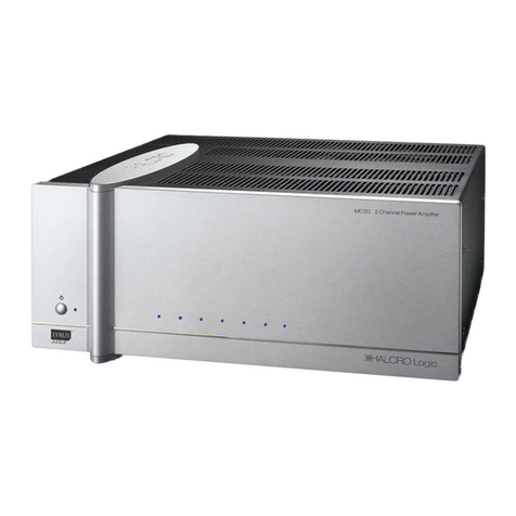
Halcro MC70 User manual

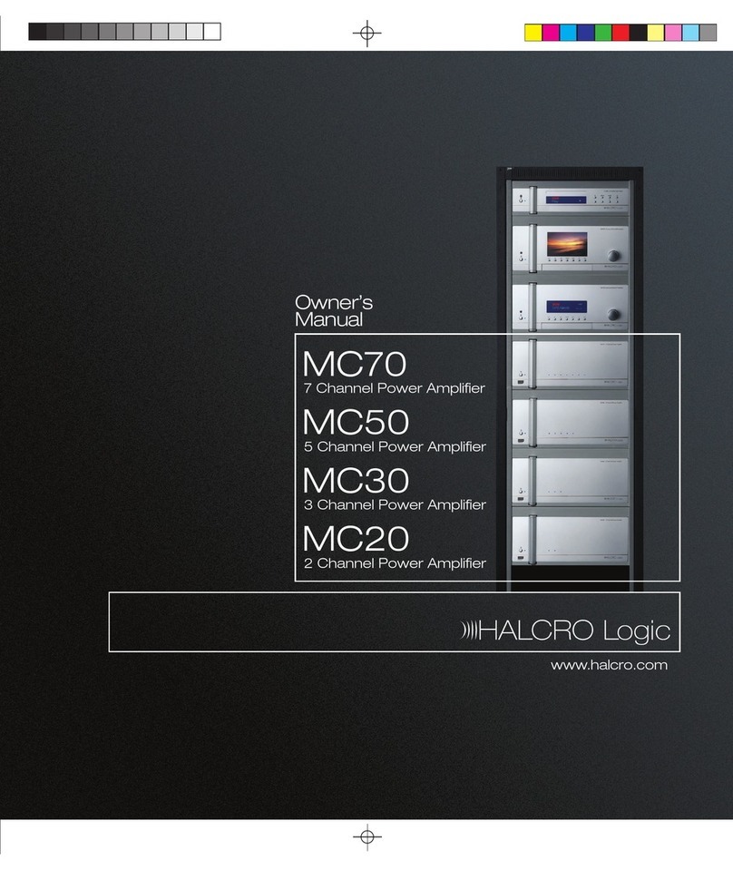
Owner’s
Manual
MC70
7 Channel Power Amplifier
MC50
5 Channel Power Amplifier
MC30
3 Channel Power Amplifier
MC20
2 Channel Power Amplifier
www.halcro.com

1
Contents
Introduction................................................3
Important Safety Information...................5
Symbols ......................................................... 5
Electrical safety............................................. 5
Protection from fluids .................................. 6
Service warnings .......................................... 6
Protection from overheating .......................7
Additional Important Safety Instructions for
US ................................................................... 8
Interference warning - US FCC Regulations
........................................................................ 9
Wiring to the Loudspeaker Terminals to
Class 2 Wiring (US Wiring Regulations)..... 9
MC20 Features ........................................11
MC30 Features ....................................... 12
MC50 Features ....................................... 13
MC70 Features........................................ 14
Installation................................................. 15
Unpacking ....................................................15
Storing packaging .......................................15
Positioning....................................................15
Controls and Connections..................... 16
Front panel ................................................... 17
Rear panel .................................................... 17
MC20/30/50/70 inputs ..............................18
Connecting loudspeakers .........................18
Connecting an audio source.................... 20
Connecting a processor ............................21
Connecting the trigger .............................. 22
Connecting to a PC ................................... 22
Connecting the mains supply cable........ 22
Break-in period........................................... 22
Operation................................................. 23
Starting up................................................... 23
Shutting down ............................................ 23
Care and Maintenance.......................... 24
Cleaning....................................................... 24
Troubleshooting ..................................... 25
Halcro Reliabilty Assurance Service
(HRAS) ..................................................... 26
Installing HRAS Monitor software ............ 26
Launching HRAS Monitor ......................... 27
Setting up HRAS Monitor.......................... 27
Viewing the events log .............................. 36
Shutting down HRAS Monitor .................. 38
Uninstalling HRAS Monitor........................ 38
Communications .................................... 39
Setting the IP address ............................... 39
Ethernet communications ........................ 39
Serial communications.............................. 39
Service and Warranty Information ....... 42
Overview ..................................................... 42
Product warranty ....................................... 42
Exclusions to the warranty ....................... 42
Transferability.............................................. 43
Warranty verification.................................. 43
Warranty registration................................. 43
If service is required................................... 43
Transportation of products ...................... 44
Freight damage claims.............................. 44
If you have moved ..................................... 44
Thank you for choosing Halcro!............... 44
Index......................................................... 45

2

3
Introduction
Congratulations on purchasing the Halcro
Logic MC20, MC30, MC50 or MC70 multi-
channel power amplifier.
Born from a decade of high-performance
two-channel Research and Development that
produced the world’s finest super-high-end
amplification systems, comes home theater at
the highest level.
Halcro Logic provides unprecedented levels
of leading technology, resulting in reliability and
Super-Definition performance.
Halcro Logic is used throughout the world by
home theater connoisseurs with a genuine
love and passion for home entertainment at its
best.
Halcro has enjoyed creating perfect audio
reproduction for the world's music
connoisseurs.
Please enjoy the Halcro Logic audio
experience.
If you wish to contact Halcro to give us
feedback on your purchase or for general
enquiries, please feel free to:
or phone: +61 8 8372 7869.
Amplification for your home theater system
must meet a stringent set of requirements. It
must have a dynamic range to suit the most
explosive action, the subtlest of tender
moments and all that lies between. It must not
distract with any intrusive distortion, and it
must deliver all of this with pinpoint timing and
accuracy.
Each Halcro Logic multi-channel amplifier is a
powerhouse that responds precisely to each
of these demands, utilizing LYRUS™
technology to ensure the maximum detail and
impact is drawn from all soundtracks.
LYRUS™ amplification technology was
developed by Bruce Candy, one of the
world's leading commercial physicists and a
passionate audiophile. LYRUS™ is the only
genuine high-performance Class D
amplification technology on the world market.
It delivers very low levels of Total Harmonic
Distortion (THD), the key feature of the Halcro
range of monoblock and stereo amplifiers.

4

5
Important Safety Information
Symbols
The following symbols are used on this
equipment:
The lightning flash with
arrowhead symbol, within an
equilateral triangle, is intended to
alert the user to the presence of
uninsulated ‘hazardous voltage’
that may be of sufficient
magnitude to constitute a risk of
electric shock to a person if
exposed or contacted.
The exclamation point within an
equilateral triangle is intended to
alert the user to the presence of
important operating and
maintenance (servicing)
instructions in the following
pages.
The ‘CE’ symbol indicates
compliance of this device with
the relevant directives of the
European community including
the EMC (Electromagnetic
Compatibility) and LVD (Low
Voltage Directive) standards.
Warning of electrical shock
hazard. Do not open cover
(or back). There are no user
serviceable parts inside.
Refer servicing to qualified
service personnel.
Electrical safety
WARNING: This product must
always be connected to a
mains socket outlet with a
protective earth connection.
Only use a suitable approved mains cord
complying with European individual country
requirements in the CE Low Voltage Directive
Scheme.
DANGER: Do not
open the cover or
back, or remove any
panels, or try to
modify or repair the
MC20/30/50/70.
Opening the
MC20/30/50/70 may
expose you to
dangerous voltages
and will void the
warranty.
WARNING: The Standby/On
button does not disconnect the
unit from the mains power.
To disconnect the unit from the
mains, switch off the unit at the
mains socket outlet and
withdraw the mains plug from
the socket outlet.

6
The unit should be installed in a position where
the mains plug is easily accessible. Disconnect
the unit from the mains if it is to be left unused
for a long period.
WARNING: No naked flame
sources, such as lighted
candles, should be placed on
the unit.
If naked flame sources tip over
they could result in a fire.
Protection from fluids
The Halcro Logic MC20/30/50/70 units are
designed for indoor use only and are not
protected against liquids. They must not be
exposed to dripping or splashing and no
objects filled with liquids, such as vases,
should be placed on them.
If liquid is accidentally spilled on the device,
immediately disconnect the unit from the
mains. Allow sufficient time for complete
evaporation before using the MC20/30/50/70
again. If the liquid is anything other than water,
do not use the device before a qualified
service technician has examined it.
Cleaning may be performed with a slightly
damp cloth that has been wrung until nearly
dry. Refer to the section on Cleaning on
page 24.
WARNING: To reduce the risk
of fire or electric shock, do not
expose this equipment to rain
or moisture.
Do not allow liquids to enter
the unit or contact electrical
terminals.
Service warnings
All compartments are sealed at the factory. If
the seals are broken, the warranty will be void
and all service costs will be charged to the
owner.
DANGER: Contains no user
serviceable parts. Do not
attempt to open any of the
MC20/30/50/70
compartments as this may
expose you to dangerous
voltages and will void the
warranty.

7
Requires F 10A L 250V fuse for continued
protection against the risk of fire. Never
bypass or use any other type of fuse. The fuse
is located on the rear panel of the multi-
channel power amplifier (13).
WARNING: Always replace the
fuse with the same type and
rating as specified:
F10AL250V.
Always disconnect the unit
from the mains before
touching the loudspeaker
terminals or replacing the fuse.
Protection from overheating
The MC20/30/50/70 generates a certain
amount of heat and requires ventilation. Slots
and ventilation holes are provided for
ventilation purposes, and to ensure reliable
operation of the product. To prevent fire
hazards, these openings must never be
blocked or covered.
The MC20/30/50/70 may be stacked on top
of a Halcro Logic SSP180/220 amplifier but
overheating may result if ventilation is
inadequate. Ensure there is at least 4 in
(10 cm) above the uppermost unit for
ventilation.
Follow the precautions listed below. If these
precautions are not followed, overheating or
failure may result. Overheating also shortens
the working life of all components.
do not block the ventilation holes in the
top or bottom of the unit with any object,
including paper, cloths or curtains
do not place the unit on a soft surface
such as a rug, or carpet with a thick pile,
into which it could sink
avoid placing the unit in a built-in
installation place such as a bookcase or a
rack unless you can provide proper
ventilation
do not operate the unit inside a cabinet
unless it has adequate ventilation (such
as an open back panel)
allow at least 4 in (10 cm) on all sides of
the unit (except the bottom)
WARNING: Do not obstruct
ventilation slots in the chassis.

8
Additional Important Safety Instructions for US
The following instructions should be followed
by customers in the USA in addition to the
safety instructions in the rest of this chapter:
oRead these instructions.
oKeep these instructions.
oHeed all warnings.
oFollow all instructions.
oDo not use this apparatus near water.
oClean only with dry cloth or according to
the cleaning instructions.
oDo not block any ventilation openings.
oInstall in accordance with the
manufacturer’s instructions.
oDo not install near any heat sources such
as radiators, heat registers, stoves, or
other apparatus (including amplifiers) that
produce heat.
oDo not defeat the safety purpose of the
polarized or grounding-type plug.
A polarized plug has two blades, with one
wider than the other. A grounding type
plug has two blades and a third
grounding prong. The wide blade or the
third prong is provided for your safety. If
the provided plug does not fit into your
outlet, consult an electrician for
replacement of the obsolete outlet.
Additional instructions continued:
oProtect the power cord from being
walked on or pinched particularly at
plugs, convenience receptacles, and the
point where they exit from the apparatus.
oOnly use attachments/accessories
specified by the manufacturer.
oUnplug this apparatus during lightning
storms or when unused for long periods
of time.
oRefer all servicing to qualified service
personnel.
Servicing is required when the apparatus
has been damaged in any way, such as if
the power-supply cord or plug is
damaged, liquid has been spilled, or
objects have fallen into the apparatus, if
the apparatus has been exposed to rain
or moisture, does not operate normally,
or has been dropped.

9
Interference warning - US
FCC Regulations
This equipment has been tested and found to
comply with the limits for a Class B digital
device, pursuant to part 15 of the FCC Rules.
These limits are designed to provide
reasonable protection against harmful
interference in a residential installation. This
equipment generates, uses, and can radiate
radio frequency energy and, if not installed
and used in accordance with the instructions,
may cause harmful interference to radio
communications. However, there is no
guarantee that interference will not occur in a
particular installation.
If this equipment does cause harmful
interference to radio or television reception,
which can be determined by turning the
equipment off and on, the user is encouraged
to try to correct the interference by one or
more of the following measures:
oIncrease the separation between the
equipment and receiver.
oConnect the equipment into an outlet on
a circuit different from that to which the
amplifier is connected.
oConsult the dealer or an experienced
radio/TV technician for help.
Changes or modifications not expressly
approved by Halcro could void the user's
authority to operate the equipment.
Wiring to the Loudspeaker
Terminals to Class 2 Wiring
(US Wiring Regulations)
This equipment has been classified as having
a Class 2 loudspeaker output requiring wiring
to connect the output terminals to class 2
according to the National Electrical Code.
Consult a qualified installer or electrical
contractor for further information.


11
MC20 Features
Features of the Halcro Logic MC20 include:
2-channel rack mountable or free
standing multi-channel power amplifier
400 watts per channel
unbalanced and balanced voltage inputs
mains voltage: 100-240 V AC
remote trigger switch between On and
Standby
full control via RS232 or ETHERNET
connection
Command Functions:
switch between On and Standby
ability to inhibit individual amplifier
modules
amplifier module will indicate over-
temperature condition
amplifier module will indicate over-
current condition
Halcro Reliability Assurance Service
(HRAS)

12
MC30 Features
Features of the Halcro Logic MC30 include:
3-channel rack mountable or free
standing multi-channel power amplifier
400 watts per channel
unbalanced and balanced voltage inputs
mains voltage: 100-240 V AC
remote trigger switch between On and
Standby
full control via RS232 or ETHERNET
connection
Command Functions:
switch between On and Standby
ability to inhibit individual amplifier
modules
amplifier module will indicate over-
temperature condition
amplifier module will indicate over-
current condition
Halcro Reliability Assurance Service
(HRAS)

13
MC50 Features
Features of the Halcro Logic MC50 include:
5-channel rack mountable or free
standing multi-channel power amplifier
350 watts per channel
unbalanced and balanced voltage inputs
mains voltage: 100-240 V AC
remote trigger switch between On and
Standby
full control via RS232 or ETHERNET
connection
Command Functions:
switch between On and Standby
ability to inhibit individual amplifier
modules
amplifier module will indicate over-
temperature condition
amplifier module will indicate over-
current condition
Halcro Reliability Assurance Service
(HRAS)

14
MC70 Features
Features of the Halcro Logic MC70 include:
7-channel rack mountable or free
standing multi-channel power amplifier
350 watts per channel
unbalanced and balanced voltage inputs
mains voltage: 100-240 V AC
remote trigger switch between On and
Standby
full control via RS232 or ETHERNET
connection
Command Functions:
switch between On and Standby
ability to inhibit individual amplifier
modules
amplifier module will indicate over-
temperature condition
amplifier module will indicate over-
current condition
Halcro Reliability Assurance Service
(HRAS)

15
Installation
Ensure you have read the Important Safety
Information on page 5, before installing your
Halcro multi channel power amplifier.
If you require assistance in the unpacking and
installation of your Halcro multi channel power
amplifier, please contact your dealer.
Unpacking
Unpack the unit carefully, noting that all
components are present and undamaged.
Your carton should contain the following
items:
MC20, MC30, MC50 or MC70, as
ordered
mains supply cable (USA and EU)
three feet (for stacking)
Owner’s Manual and Warranty Card
CD containing HRAS software
Storing packaging
The packaging is custom designed to prevent
damage from occurring during transport.
Store the packaging in a dry location.
Positioning
We suggest that the Halcro multi channel
power amplifier be positioned as near to your
front loudspeakers as practical. The unit
houses several heat sinks that are used to
dissipate heat. The airflow to these should not
be interrupted. Ensure there is at least four
inches (ten centimeters) clearance around the
vents.
Do not connect to mains power
until all the connections are
made and checked.

16
Controls and Connections
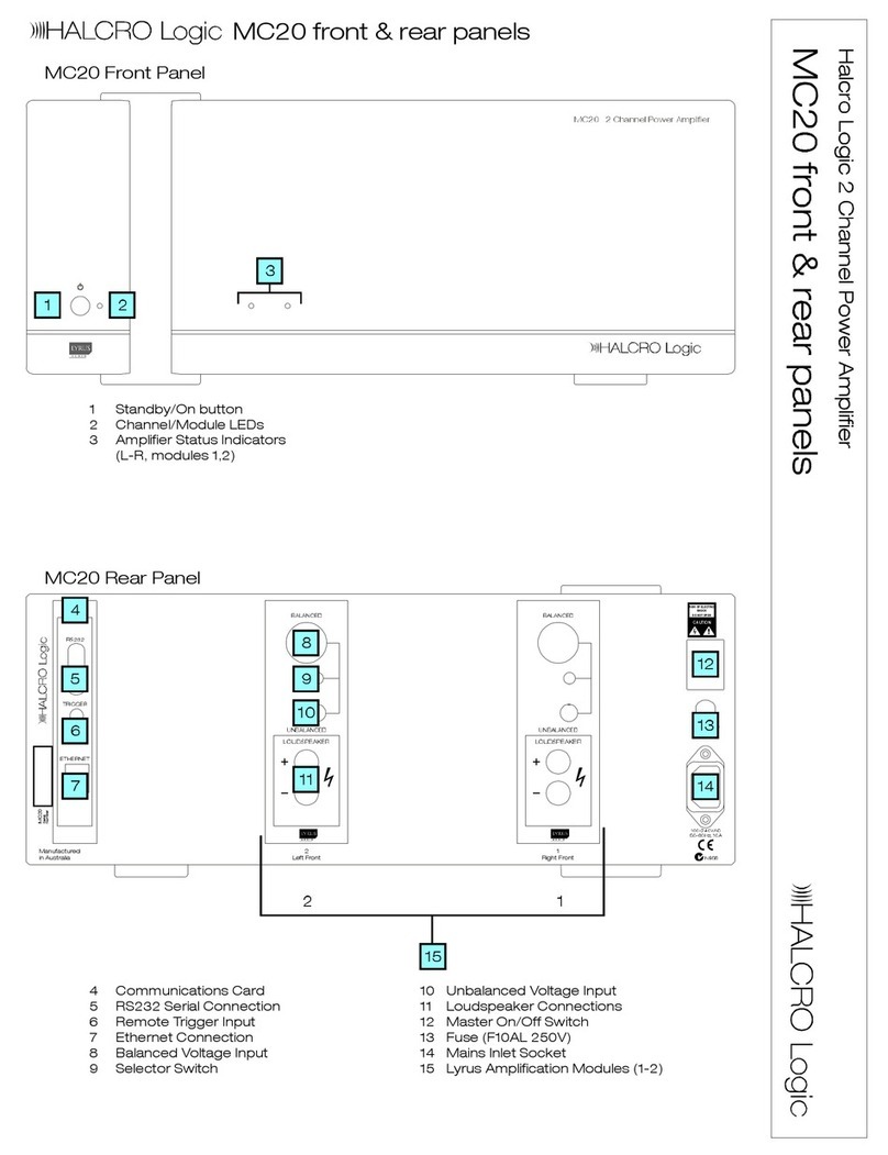
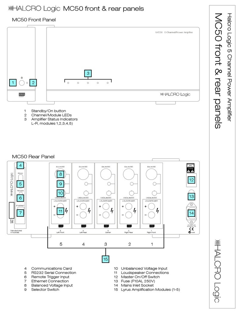
The numbers shown on the diagram below
are used throughout the manual to refer to
the individual controls and connections on the
front and rear panel. Refer to this page for a
quick reference to all controls and
connections.

17
Front panel
1 Standby/On button
Switches the multi-channel power
amplifier between Standby and ON.
2 Power LED
LED indicating the unit is in Standby
mode.
3 Amplifier status indicators
LEDs indicating the status of the amplifier
modules.
Rear panel
4 Communications card
RS232, trigger and Ethernet connections
to computers or home automation
systems or control center.
5 Ethernet connection
Connects to a PC.
6 Trigger connection
Connects to a control center such as the
Halcro Logic SSP180/220 to allow it to
control the multi-channel power amplifier.
7 RS232 connection
Interface for connection to a home
automation system or computer
network.
8 Balanced voltage input
Connects to an audio source such as a
CD player.
9 Selector switch
Selects balanced or unbalanced voltage
input.
10 Unbalanced voltage input
Connects to an audio source such as a
CD player.
11 Loudspeaker connections
Positive and negative loudspeaker
connections (maximum of seven in the
MC70).
12 Master On/Off switch
13 Fuse
14 Mains inlet socket
15 Amplification modules
Connections to up to seven (in the
MC70) amplification modules comprising
audio input and loudspeaker connections

18
MC20/30/50/70 inputs
Connect the audio source to the required
input, and make sure the selector switch is in
the correct position: up for balanced voltage
input; down for unbalanced voltage input.
Balanced voltage input:
High impedance: suitable for a standard
preamplifier or CD player for example. XLR
output.
Input impedance: 10 kohms + 10 kohms.
Unbalanced voltage input:
High impedance: suitable for a standard
preamplifier or CD player for example. RCA
output.
Input impedance: 10 kohms.
Connecting loudspeakers
There may be voltages
present at the loudspeaker
terminals, which may present
an electric shock hazard if
touched. Always ensure the
unit is switched to OFF or
Standby mode when
connecting or disconnecting
loudspeakers.
Each amplification module is numbered and
named (15) for your convenience. To ensure
peak performance, and share the load equally
between the power supplies, we recommend
you connect the speakers as designated by
name. For example, connect the Left Front
speaker cable to 'L.Front' on your
MC20/30/50/70. (Refer to the diagram on
following page.)
Each amplification module has two
loudspeaker terminals (11):
Positive + (red)
Negative - (black)
To connect the loudspeakers, connect the
positive (red) terminal of the multi-channel
power amplifier to the positive (red) terminal of
the designated loudspeaker. This will ensure
correct phasing of the audio signal. We
recommend only one loudspeaker be
connected to each amplifier module. Ensure
the loudspeaker terminals are securely
tightened, but do not over-tighten to the point
of damaging the connection.
Use only loudspeaker cables with well-
insulated terminals.
DO NOT SHORT-CIRCUIT THE TERMINALS.

19
Connecting loudspeakers
Other manuals for MC70
2
This manual suits for next models
3
Table of contents
Other Halcro Amplifier manuals

Halcro
Halcro MC30 User manual

Halcro
Halcro Eclipse mono User manual

Halcro
Halcro Eclipse stereo User manual

Halcro
Halcro DM38 User manual

Halcro
Halcro DM8 User manual

Halcro
Halcro SSP100 Quick start guide

Halcro
Halcro DM10 User manual

Halcro
Halcro DM10 User manual

Halcro
Halcro DM88 User manual

Halcro
Halcro MC30 Quick start guide