Haldex EGP 90555106 User manual

L31186
(94100535)
Rev. 10/04
Immediate Response
Height Control Valve
GENERAL INFORMATION
The Haldex EGP Height Control Valve (HCV) automatically adds air to, or exhausts
air from air suspension to maintain a constant static design ride height.
-- The Haldex EGP can be used for right or left and long or short control
arm applications. Refer to installation instructions herein for proper hook-up.
-- The integral dump valve is NOT sold separately and CAN NOT be interchanged
on valves in the field.
Lever arm and link assemblies can be purchased by ordering 48100267 from your
Haldex Distributor.
NOTE: The Haldex EGP valve can be interchanged with other brands of height
control valves.
PERIODIC AIR CONTROL MAINTENANCE
Drain all moisture from air reservoir at regular intervals. Normal air system
maintenance should be practiced.
The air filter in the Haldex Pressure Protection Valve is removable and can be
cleaned or replaced, if necessary.
PRE-INSTALLATION WARNINGS
IMPORTANT: It is extremely important that the original equipment manufacturers
specifications are followed when installing a new valve. Refer to vehicle and
suspension manufacturers instructions for location of the valve. Stop engine when working
under a vehicle. Always block the vehicle wheels to prevent a fore or aft roll. Bleeding off
system air pressure may cause the vehicle to roll. Keep hands away from brake chamber
push rods and brake adjusters; they may apply as
system pressure drops. Never exceed recommended working air pressure and always wear
safety glasses when working with air pressure. Never look directly into component ports or
direct a pressurized air flow at anyone. Never attempt to disassemble a component until you
have read and understood all recommended procedures. Some components contain power-
ful springs and injury can result if not properly disassembled. use only proper tools and
observe all precautions
pertaining to the use of those tools.
CAUTION: Prior to disconnecting or connecting any airlines or valves, bleed off all air
pressure from the air supply system. Failure to do so can result in severe injury.
DO NOT install a single height control valve of any type if the suspension or
vehicle manufacturer specifies a two (2) height control valve system.
DO NOT use a time delay valve with a EGP valve on the same vehicle.
DO NOT use antifreeze or other solvents in air supply line. Use of solvents or antifreeze
can damage seals and void the valve warranty.
ALWAYS use a Pressure Protection Valve (PPV) and filter such as Haldex 90554107.
Attach PPV directly to the air reservoir for supply to the EGP.
EGPEGP
Type

1. Prepare the vehicle for installation. A Haldex EGP can be installed
in a vertical or horizontal position with the control arm in either right-hand or
left-hand position.
Important: Direction arrow must be in proper position for valve to function
properly (Figure 2).
2. Install the EGP in the recommended
position by bolting it to the specified
surface using 5/16” diameter or 9 mm
mounting bolts (For mounting bolt spacing
see Figure 1).
3. Connect the air supply line to the air supply
port of the EGP. If using 90555106, supply
port is the top port 1 (Figure 3).
Figure 2 - Vertical & Horizontal Installation
PRE-INSTALLATION WARNINGS (Cont’d) INSTALLATION INSTRUCTIONS (continued)
Actuator Shaft Detail
Remove brass retaining block by pulling retaining
clip at corner. Rotate 90° and reinsert into housing
for (left or right) horizontal shaft installation.
Insert Control Arm in EGP Height Control Valve with direction arrow on shaft
in proper location.
Part Number Replaces Dump Valve Ports
90554241 - 1/4” NPT
90554243 - 1/4” NPT
90554271 Normally Open* 1/4” NPT
90554273 Normally Open* 1/4” NPT
* Needs air pressure to activate dump valve
90555105
90555106
INSTALLATION INSTRUCTIONS
Figure 1. EGP Reference Dimension Details
ALWAYS use a Pressure Protection Valve (PPV) and filter
such as Haldex 90554107. Attach PPV directly to the air
reservoir for supply to the EGP.

INSTALLATION INSTRUCTIONS (continued) INSTALLATION INSTRUCTIONS (continued)
EGP Valve
with Dump
Air Spring
Air Spring
Pressure
Protection
Valve
Air Tank
Manual
Switch
Air Spring
Air Spring
Electric
Solenoid
Valve
Front of Vehicle
To Air
Springs
To Air
Springs
To
Manual Switch
To
Air Tank
To Air
Springs
To Air
Springs
To
Manual
Switch
To
Air Tank
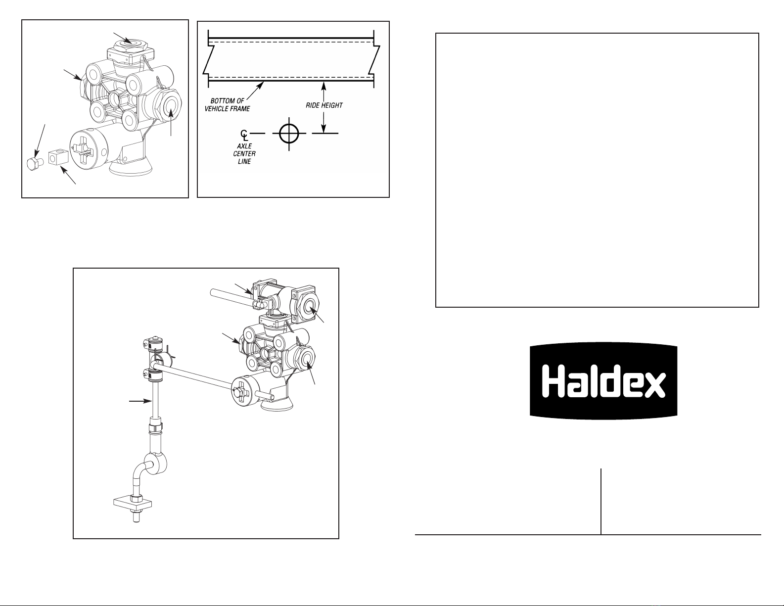
4. Connect the air spring port(s) to the air spring(s) port(s) (as shown in Figure 3)
for either vertical or horizontal position. If only one air spring port is used, other
port must be plugged.
5. Install the EGP control arm. Refer to Figure 2 for proper control arm
installation.
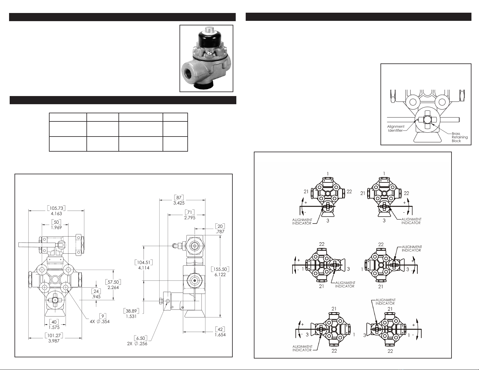
Note: Correct position of the direction arrow on the valve actuator shaft to the
direction of the control arm is critical. Incorrect installation will impair suspension
and vehicle performance. (Refer to Figure 2.)
6. To insure that the control arm is properly installed, temporarily supply air
pressure to the EGP and rotate the control arm up (approximately 20°
above horizontal) and check if air pressure begins to inflate the air spring(s).
If the air springs are not being inflated, recheck the air lines for proper port
connection and the control arm and actuation shaft for proper position.
If the EGP properly inflates the air spring(s), rotate control arm down
(approximately 20° below horizontal) to check if air pressure is being
exhausted from the air spring(s) through the exhaust port of the EPG. Once
it has been determined that the control arm is in the proper position torque the
locking bolt to 6-8 ft/lbs. (Refer to Figure 5).
1. Place vehicle on level ground.
2. Build and maintain a minimum of 70 PSI air pressure.
3. Disconnect the lower anchor of the vehicle link from the axle mount.
4. Place the lever arm into the horizontal position by aligning the arrow and hole
on the shaft with the slot in the housing.
5. Place a 4mm pin in the hole to hold this position temporarily. NOTE: IF THE
VALVE IS OUT OF ADJUSTMENT, THE VALVE WILL BE EXHAUSTING AIR
OR SUPPLYING AIR TO THE AIR SPRINGS.
6. Remove rubber cap, loosen the locking nut. (Figure 4)
7. Using a screw driver, turn the adjustment screw clockwise until the valve will
begin supplying air to the air bags. (Figure 4)
8. Turning the adjustment screw counter-clockwise, count the number of turns
until the valve begins to exhaust air.
9. Turn the adjustment screw clockwise 1/2 the number of turns between filling
and exhausting to set proper neutral position.
10. Treat the lock nut with Loctite 290 or equivalent and tighten it hand tight,
using the screw driver to maintain neutral position.
11. Replace rubber cap.
SETTING THE NEUTRAL POSITION
Figure 3.
12. Insert the lower anchor of the vertical link to the axle mount, loosen the jam
nut(s) and turn until the vehical kink is free from binding.
13. Remove the 4mm pin holding the neutral position.
14. Install and tighten the lock washer and nut.
Figure 4.
Locking
Nut
Adjustment
Screw
Rubber
Boot

Figure 5. Figure 6.
Figure 7.
Rev. 10/04 ART ONLY L31186 (94100535)
EGP locked in neutral position with
plastic pin, install link assembly and
adjust for ride height by moving
universal connector up or down link
assembly rod.
Note: Tighten clamps then remove
plastic pin after adjustment has
been made.
48100267
These Additional Parts Available From Haldex Will Enable You To:
Upgrade your Pressure Protection Valve to include an inline filter.
Part No. Description
90554107 .... PPV With Inline Filter
Add a suspension dump feature to your truck or trailer.
Part No. Description
90054088 .... For Switch To Pilot Manual Dump Valves
90554615 .... For Remote Mounted “Auto” or Manual Dump Installations
Weigh your vehicle.
Part No. Description
42123039 .... SM130 Economic Pressure Gauge and Decal
42123040 .... SM140 Robust Pressure Gauge and Decal; Mounted in a
Weatherproof Fiberglass Box
42123041 .... SM240 Robust Pressure Gauge and Decal; Mounted in a
Weatherproof Fiberglass Box
Or both weigh your vehicle and lower your suspension.
Part No. Description
42123026 .... SMD111 Robust Pressure Gauge, Pilot Valve, Switch and Decal;
Mounted in a Weatherproof Fiberglass Box
42123031 .... SM115 Robust Pressure Gauge, Switch and Decal; Mounted in
a Weatherproof Fiberglass Box
North American Sales Division
Haldex Limited
525 Southgate Drive, Unit 1
Guelph, Ontario Canada N1G 3W6
Phone: 519-826-7723
Fax: 519-826-9497
North American Sales Division
Haldex Brake Products Corporation
10707 NW Airworld Drive
Kansas City, MO 64153-1215
Phone: 816-891-2470
Fax: 816-801-4198
Commercial Vehicle Systems
www.haldex.com · www.hbsna.com
Set ride height according to vehicle
OEM specifications.
Locking
Nut
Brass Retaining Block
Air
Springs
Air
Springs
Supply
Air
Springs
Air
Springs
Supply
Pilot
TO ADJUST VEHICLE
RIDE HEIGHT
This manual suits for next models
1
Other Haldex Control Unit manuals
Popular Control Unit manuals by other brands

Texas Instruments
Texas Instruments TPS54335AEVM-010 user guide

Omron
Omron CS1W-213 - REV 02-2008 Operation manual

mikroElektronika
mikroElektronika click BOARD IR reflect click manual

Moog
Moog G761 Series Installation and operation instruction

Blain Hydraulics
Blain Hydraulics L10 manual

WAGO
WAGO 750-439 manual

Sleipner
Sleipner ECU user manual

Agilent Technologies
Agilent Technologies 83481A user guide

Rohm
Rohm LAPIS Semiconductor ML22Q663 manual

Evinrude
Evinrude I-command user guide

Roger Technology
Roger Technology H70/104AC Instruction and warnings for the installer

Extron electronics
Extron electronics AC 102 installation guide