vii
LIST OF FIGURES
Number Title Page
Figure 1. Centrifugal Force From A Rotating Disk ...........................................................................8
Figure 2. Single Stage Water Flow ...................................................................................................9
Figure 3. Clearance Ring Water Flow............................................................................................ 10
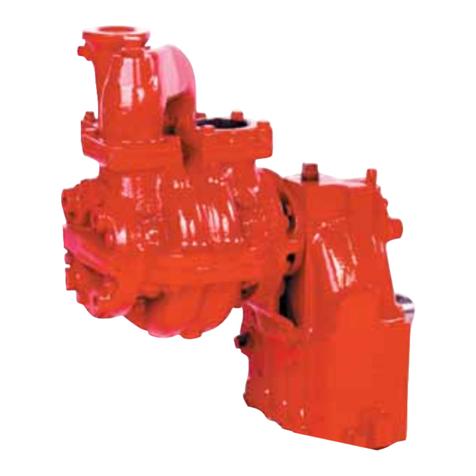
Figure 4. Parts Of The Hale Booster Pump................................................................................... 11
Figure 5. Mechanical Seal ............................................................................................................. 12
Figure 6. Direct Engine Mount....................................................................................................... 14
Figure 7.Hale Anode...................................................................................................................... 14
Figure 8. Driver Compartment Indicator Lights ............................................................................ 18
Figure 9. Pump Operator Panel..................................................................................................... 19
Figure 10. Results Of Cavitation.................................................................................................. 26
Figure 11. Low Pressure Regions................................................................................................ 27
Figure 12. Typical Gearbox Oil Fill/Level Component Locations ............................................... 36
Figure 13. Engine Or Opposite Engine Rotation ......................................................................... 47
Figure 14. Circlips (How To Recognize And Remove Them) ...................................................... 51
Figure 15. Measuring For Worn Clearance Rings And Impeller Hubs....................................... 53
Figure 16. Seal Removal Tool And Seal Driver Kit...................................................................... 55
Figure 17. Caliper (Depth Rod Extended) ................................................................................... 55
Figure 18. Pump And Gearbox Assembly R&R ........................................................................... 57
Figure 19. One-Piece Volute (AP, CBP, MBP) .............................................................................. 59
Figure 20. Three-Piece Volute (RSD) ........................................................................................... 59
Figure 21. AP Pump Exploded View............................................................................................. 61
Figure 22. CBP Pump Exploded View .......................................................................................... 62
Figure 23. MBP Pump Exploded View ......................................................................................... 63
Figure 24. RSD Pump Exploded View.......................................................................................... 64
Figure 25. Gearbox Exploded View (All Except 3.74:1 GR) ........................................................ 65
Figure 26. Gearbox Exploded View (3.74:1 GR) ......................................................................... 66
Figure 27. AP/MBP Volute R&R................................................................................................... 72
Figure 28. MBP Inducer R&R....................................................................................................... 77
Figure 29. RSD Inducer R&R ....................................................................................................... 77
Figure 30. MBP Impeller R&R...................................................................................................... 82
Figure 31. AP Impeller R&R ......................................................................................................... 84
Figure 32. CBP Impeller R&R....................................................................................................... 87
Figure 33. NORD-lock Washers Installation Details ................................................................... 89
Figure 34. Typical Mechanical Seal Detail.................................................................................. 91
Figure 35. RSD Mechanical Seal Notch ...................................................................................... 94
Figure 36. Align Slot On Seal With Pin In Pump Head................................................................ 95
Figure 37. Pump Head (Pump Side).......................................................................................... 100
Figure 38. Pump Head (Drive Side)........................................................................................... 101
Figure 39. Slots Cut In Clearance Ring–Volute......................................................................... 111
Figure 40. Clearance Ring Driven Out–Volute.......................................................................... 111
