manuals.online logo
Brands
  1. Home
  2. •
  3. Brands
  4. •
  5. Halma
  6. •
  7. Lock
  8. •
  9. Halma BEA 10MAGLIFELOCK9 User manual

Halma BEA 10MAGLIFELOCK9 User manual

2 Specications
MAGLIFE LOCK
USER’S GUIDE
ELECTROMAGNETIC LOCK
1 Description
The Electromagnetic Lock (Maglife) series is a surface mounted magnetic lock assembly. It is a narrow prole model available in single
and dual lock varieties and various sizes (force) designed for standard installation on most types of doors.
DESCRIPTION 10MAGLIFELOCK9
Holding Force (lbs) 100
Imput Voltage (VDC) 12 to 24
Current Draw: @ 12 VDC (amps)
@ 24 VDC (amps)
0.06
0.12
Dimensions: inches
(mm)
2.76 x 1.40 x 0.79
(70 x 35 x 20)
Weight: lbs
(kg)
0.55
0.24
Material: Lock Housing
Armature / Strike Plate
Aluminum
Zinc Plated Steel
75.5293.03 20090317 Page 1 of 2
3 Precautions
Shut off all power going to header before attempting any wiring procedures.
Maintain a clean & safe environment when working in public areas.
Constantly be aware of pedestrian trafc around the door area.
Always stop pedestrian trafc through the doorway when performing tests that may result in unexpected reactions by the door.
Always check placement of all wiring before powering up to insure moving door parts will not catch any wires and cause damage to equipment.
Ensure compliance with all applicable safety standards and building codes upon completion of installation.
4 Installation Tips
1. DO NOT touch the lock face with your hands.
2. Should the surface plating be damaged, use a soft, clean dry cloth or abrasive cloth to clean the lock face. DO NOT use sand paper. A rust inhibitor can the be
applied to the armature/strike plate and maglock assembly face.
10MAGLIFELOCK9
CAUTION
THE 10MAGLIEFLOCK9 IS DESIGNED TO BE
USED WITH A DC POWER SOURCE ONLY.
DO NOT ATTEMPT TO USE THIS PRODUCT
WITH A 24V STEP DOWN TRANSFORMER AND
A BRIDGE RECTIFIER OR SERIOUS DAMAGE
WILL OCCUR TO THE MAGLOCK. A 24V
STEP DOWN TRANSFORMER AND BRIDGE
RECTIFIER CIRCUIT WILL YIELD VOLTAGE
ABOVE 29V, WHICH EXCEEDS THE LIMITS OF
THE SPIKE SUPPRESSION CIRCUIT IN THE
MAGLOCK, CAUSING PRODUCT FAILURE.
IT IS HIGHLY RECOMMENDED THAT ONLY A
FILTERED DC POWER SOURCE BE USED TO
POWER THE 10MAGLIFELOCK9.
Page 2 of 2 75.5293.03 20090317
Do not leave problems unresolved. If a satisfactory solution cannot be achieved after troubleshooting a problem, please
contact BEA Inc. If you must wait for the following workday to contact BEA, leave the door inoperable until satisfactory
repairs can be made. Never sacrice the safe operation of the automatic door or gate for an incomplete solution.
The following numbers can be called 24/7. For more information, visit www.beasensors.com.
7 Company Contact
US and Canada:
Canada:
Northeast:
1-866-249-7937
1-866-836-1863
1-866-836-1863
Southeast:
Midwest:
West:
1-800-407-4545
1-888-308-8843
1-888-419-2564
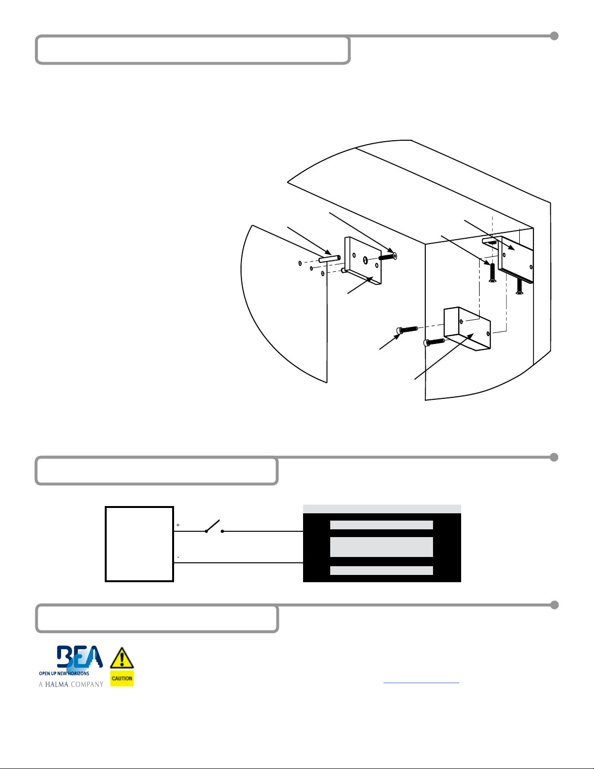
1. Inspect the frame header to determine if an angle bracket or ller plate is required.
2. Fold the enclosed mounting template on the dotted line and then mark and drill
holes as indicated. Drill two 1/8” (3.1 mm) holes at the locations marked ‘B’. For
single doors, locate the template against the door and header on the lock jamb
side of the frame.
3. Disassemble the mounting plate from the maglock assembly using the enclosed
hex key. Insert 2 screws into the slotted holes and secure the mounting
plate to the doorframe using two of the #8 mounting screws. Do not
tighten these screws fully until the maglock is properly aligned.
4. Gently tap (2) 3/16” (5mm) spring pins into the rear side of
the armature(s). Drill matching holes on the door to
receive these pins.
5. Align armature/strike plate to magnet, and then
drill a 5/8” (16mm) hole in door for sexnut and
aluminum reinforcement tube for hollow doors.
Using the M8 x 1.25 x 40mm hex head screw
and enclosed hex key, mount armature to door
using two metal and one rubber washers.
6. Continue to fasten mounting plate to heading
using remaining screws. Then, reassemble
maglock assembly to mounting plate.
7. Route the enclosed wiring harness through
the rectangular hole in the mounting plate.
Make the electrical connection as shown
below.
8. Make sure that armature/strike plate can be
shaken slightly. This will permit full armature
contact and maximize holding force.
5 Installation - Mechanical
6 Installation - Electrical
ARMATURE /
STRIKE PLATE
MOUNTING PLATE
MOUNTING
SCREWS
MAGLOCK
ASSEMBLY
MOUNTING PLATE
ASSEMBLY SCREWS
TUBES
ARMATURE / STRIKE
PLATE SCREW
RED
BLACK
DC
POWER
SUPPLY
- ONLY -
SWITCH

Other Halma Lock manuals

Halma Fortress amGardpro User manual

Halma

Halma Fortress amGardpro User manual

Halma FORTRESS Alfred User manual

Halma

Halma FORTRESS Alfred User manual

Popular Lock manuals by other brands

Best 48H installation instructions

Best

Best 48H installation instructions

Passtech PT300 user guide

Passtech

Passtech PT300 user guide

INSYS TwinLock B670 CashProtect DS manual

INSYS

INSYS TwinLock B670 CashProtect DS manual

Lockwood PADDE TRIMEC PRE-LOAD ES9000 Series installation instructions

Lockwood

Lockwood PADDE TRIMEC PRE-LOAD ES9000 Series installation instructions

Burg Wächter secuENTRY easy ENTRY 7602 FP Initial setup

Burg Wächter

Burg Wächter secuENTRY easy ENTRY 7602 FP Initial setup

Rivers Locking Systems D quick guide

Rivers Locking Systems

Rivers Locking Systems D quick guide

Chamberlain 9747E Series quick start guide

Chamberlain

Chamberlain 9747E Series quick start guide

Wittkopp Primor P30 Series user manual

Wittkopp

Wittkopp Primor P30 Series user manual

Sargent IN100 installation instructions

Sargent

Sargent IN100 installation instructions

Hama 00039791 Operating	 instruction

Hama

Hama 00039791 Operating instruction

Breezway Altair Series manual

Breezway

Breezway Altair Series manual

Sargent ASSA ABLOY Profile Series installation instructions

Sargent

Sargent ASSA ABLOY Profile Series installation instructions

XD Design P705.771 instructions

XD Design

XD Design P705.771 instructions

Schlage D-Series installation instructions

Schlage

Schlage D-Series installation instructions

Yale 5300LN Grade 2 installation instructions

Yale

Yale 5300LN Grade 2 installation instructions

schmersal AZ 201-B40 operating instructions

schmersal

schmersal AZ 201-B40 operating instructions

TUYA S1-TYB user manual

TUYA

TUYA S1-TYB user manual

National Cabinet Lock C8055 Dimensional drawing

National Cabinet Lock

National Cabinet Lock C8055 Dimensional drawing

manuals.online logo
manuals.online logoBrands
  • About & Mission
  • Contact us
  • Privacy Policy
  • Terms and Conditions

Copyright 2025 Manuals.Online. All Rights Reserved.