Halma Fortress amGardpro User manual

Description
For secure head retention in all applications the top M8 head xings must be used.
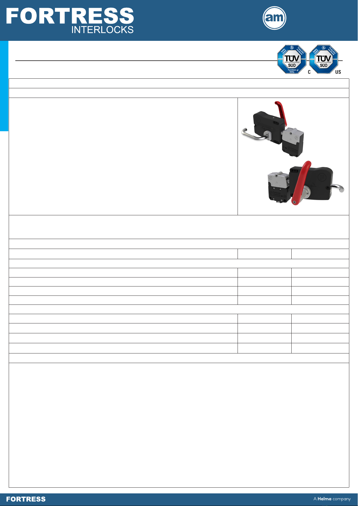
Fortress provides a single action escape release function from inside a guarded
area through the use of a head and handle application. This unit may be installed
in left or right orientation to hinged doors. The tongue incorporates a self-aligning
feature to cater for misalignment on guards. Simply turning the red handle will open
a locked guard from the inside and open the safety contacts. Releasing versions of
other modules are the type that MUST be used in conjunction with this module.
• Intuitive single action escape release handle.
• Escape release activation releases tongue and opens safety contacts.
• Handle includes Lock-Out for 4 padlocks of 8mm diameter.
• 10kN retention force.
• Stainless steel tongue is ideal for fast and frequent access.
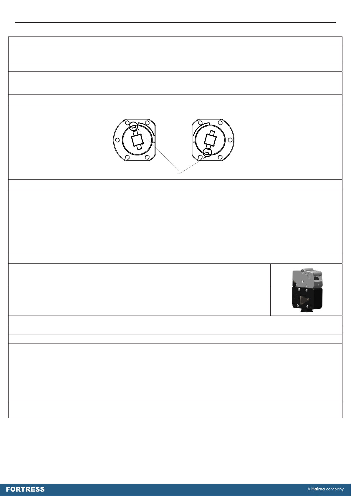
• 2 mounting position at 180° increments allowing on site handing change
possible.
• Misalignment tolerance of +/- 10mm with +/- 4° angular misalignment.
• Security tool reset after escape release actuation or auto reset function available.
• Head can be tted with lock-out device for additional lockout capability.
NOTICE!
If, as a result of risk assessment, it cannot be discounted that persons can be enclosed within a danger zone, the guard locks
with additional removable keys (safety keys) must be used or comparable measures must be taken - GS ET 19.
Options & Ordering Information
Description Part No. Handling
proHead
Security Tool Reset Escape Release Head I6 Left / Right
Security Tool Reset Escape Release Head c/w Drop Down Lock-Out I7 Left / Right
Automatic Reset Escape Release Head A6 Left / Right
Automatic Reset Escape Release Head c/w Drop Down Lock-Out A7 Left / Right
proHandle
Escape Release Handle EI2 Left
Escape Release Handle EI4 Right
Escape Release Handle - Allowing Closing of Door From Inside EJ2 Left
Escape Release Handle - Allowing Closing of Door From Inside EJ4 Right
Important:
This product is designed for use according to the installation and operating instructions enclosed. It must be installed by
a competent and qualied personnel who have read and understood the whole of this document prior to commencing
installation. If the equipment is used in a manner not specied by the manufacturer the protection provided by the equipment
may be impaired. Any modication to or deviation from these instructions invalidates all warranties.
Fortress Interlocks Ltd accepts no liability whatsoever for any situation arising from misuse or mis-application of this product.
Note: The availability of spare Actuators and Keys makes it possible to easily bypass the safety devices and, for this reason,
the security of any spare Actuators and Keys must be eectively monitored.
DO NOT LEAVE OVERRIDE/RESET KEY IN PLACE!
Always keep in a secure place, under management control, as it allows access to areas that may have a residual
hazard, and may result in incorrect operation of some devices.
Safety switches (such as a STOP or LOK) must be tted in conjunction with this unit to monitor when the Internal
Escape Release has been activated. When lock adaptors are also used it is not possible to change outside from a
STOP to a LOK (and vice versa) without other changes to the locks - seek advice from Fortress.
BEWARE OF INTENTIONAL MISUSE CAUSED BY OPERATORS WANTING TO BYPASS SAFETY SYSTEMS. THE
INSTALLER SHOULD ASSESS THE RISKS AND MITIGATE AGAINST THEM.
IF YOU HAVE ANY QUESTIONS OR QUERIES OF ANY NATURE WHATSOEVER PLEASE CONTACT THE SUPPLIER
WHO WILL BE PLEASED TO ADVISE AND ASSIST.
Operating Instructions: Single Action Escape Release
Head & Handle
1
Gard
p
r
o
p
r
o
Actuators

2
Operating Instructions: Single Action Escape Release Head & Handle
amGardpro Escape Release Head & Handle Technical Specication
Materials Housing Zinc Alloy to BSEN12844 & Stainless Steel to BS3146
Internals Stainless Steel to BS3146
Paint Finish Housing Gloss powder coat on Passivated Zinc Alloy - Black
Holding Force, F 10kN
Operating Force 5Nm
Mechanical Life ≤ 1,000,000 Switching Cycles
Shock Vibration Resistance Tested in accordance with GS-ET-19
Performance Level (EN ISO 13849-1:2015) PLe
Category (EN ISO 13849-1:2015) Cat.4
B10d 5,000,000 Operations
Environment Indoor
Ambient Temperature -5°C to 80°C (23°F to 176°F)*
Maximum Humidity 80%@<=31°C; 50%@40°C
*The units will only continue to work below freezing point (0°C) where it can be guaranteed that ice will not form on or in the unit; as it will cause the
mechanical parts to bind and jam.
amGardpro Escape Release Head Safety Functions Part No.
Safety Function 1 Retain actuator
I6 / A6 I7 / A7
Safety Function 2 Transfer motion of actuator removal into breaking of safety contacts
Safety Function 3 Unlocks during escape release & transmits motion to safety contacts
Safety Function 4 Prevents insertion of actuator when “locked out”
amGardpro Escape Release Handle Safety Functions Part No.
Safety Function 1 Provides link from interlock to door
EI / EJ
Safety Function 2 Internal handle allows escape release
Safety Function 3 On activation unit overrides locking mechanism allowing escape
Safety Function 4 Mechanism activates safety contacts
Functionality
Escape Release Opening
A single-action escape release operation can be performed by turning and operating the interior red escape release handle.
The internal mechanisms of the head and handle combination overcomes any mechanical locking means. Safety circuits are
opened.
Closing and Locking
The complete guard locking device is closed by extending and inserting the tongue of the handle into the head. The device
can then be locked by the operation of any additional mounted locking devices (e.g. Trapped key adaptors or proLOK
solenoid controlled interlock).
Unlocking and Opening
The complete guard locking device should be unlocked by the correct operation of the locking means (e.g. Trapped key
adaptors or solenoid controlled interlock). See the relevant Operating Instructions of any assembled modules for more details.
Once unlocked, the device can be opened by turning and operating the exterior silver access handle to remove the tongue
from the head.

Figure 3: Dimensional Drawing - amGardpro Escape Release Handle
Figure 1: Dimensional Drawing - amGardpro Escape Release Head
Operating Instructions: Single Action Escape Release Head & Handle
3
FORTRESS
A company
Halma
www.fortressinterlocks.com
THE COPYRIGHT OF THIS DRAWING BELONGS TO FORTRESS INTERLOCKS Ltd.
THE CONTENT OF THIS DRAWING IS CONFIDENTIAL AND MUST NOT BE
DISCLOSED TO ANY 3rd PARTY WITHOUT SPECIFIC, WRITTEN APPROVAL.
ALL DIMENSIONS
ARE IN mm UNLESS
OTHERWISE STATED A3 SCALE: 1.00 SHEET: 1 OF 6
ORIGINAL SIZE DATE: 25-02-2020 ISSUE: 0
AMGARD PRO I6 & A6 ESCAPE RELEASE HEAD DIMENSIONS DWG NO: SD-00018
I6 - ALL-IN-ONE ESCAPE RELEASE HEAD
A6 - AUTOMATIC RESET ALL-IN-ONE ESCAPE RELEASE HEAD
Figure 2: Dimensional Drawing - Escape Release Head with Padlockable Drop Down Lock-Out
FORTRESS
A company
Halma
www.fortressinterlocks.com
THE COPYRIGHT OF THIS DRAWING BELONGS TO FORTRESS INTERLOCKS Ltd.
THE CONTENT OF THIS DRAWING IS CONFIDENTIAL AND MUST NOT BE
DISCLOSED TO ANY 3rd PARTY WITHOUT SPECIFIC, WRITTEN APPROVAL.
ALL DIMENSIONS
ARE IN mm UNLESS
OTHERWISE STATED A3 SCALE: 0.75 SHEET: 2 OF 6
ORIGINAL SIZE DATE: 25-02-2020 ISSUE: 0
AMGARD PRO I7 & A7 ESCAPE RELEASE HEAD DIMENSIONS DWG NO: SD-00018
DROPDOWN LOCKOUT OPEN DROPDOWN LOCKOUT CLOSED
I7 - ALL-IN-ONE ESCAPE RELEASE HEAD WITH PADLOCKABLE DROPDOWN LOCKOUT
A7 - AUTOMATIC RESET ALL-IN-ONE ESCAPE RELEASE HEAD WITH PADLOCKABLE DROPDOWN LOCKOUT
FORTRESS
A company
Halma
www.fortressinterlocks.com
THE COPYRIGHT OF THIS DRAWING BELONGS TO FORTRESS INTERLOCKS Ltd.
THE CONTENT OF THIS DRAWING IS CONFIDENTIAL AND MUST NOT BE
DISCLOSED TO ANY 3rd PARTY WITHOUT SPECIFIC, WRITTEN APPROVAL.
ALL DIMENSIONS
ARE IN mm UNLESS
OTHERWISE STATED A3 SCALE: 0.40 SHEET: 3 OF 6
ORIGINAL SIZE DATE: 25-02-2020 ISSUE: 0
AMGARD PRO EI & EJ ESCAPE RELEASE HANDLE DIMENSIONS DWG NO: SD-00018
EI - ESCAPE RELEASE HANDLE
EJ - ESCAPE RELEASE HANDLE ALLOWING CLOSING OF DOOR FROM INSIDE

Figure 4: Mounting Drawings - amGardpro Escape Release Head and Handle
Figure 5: Mounting Drawings - amGardpro Escape Release Handle Angular Osets
FORTRESS
A company
Halma
www.fortressinterlocks.com
THE COPYRIGHT OF THIS DRAWING BELONGS TO FORTRESS INTERLOCKS Ltd.
THE CONTENT OF THIS DRAWING IS CONFIDENTIAL AND MUST NOT BE
DISCLOSED TO ANY 3rd PARTY WITHOUT SPECIFIC, WRITTEN APPROVAL.
ALL DIMENSIONS
ARE IN mm UNLESS
OTHERWISE STATED A3 SCALE: 0.40 SHEET: 5 OF 6
ORIGINAL SIZE DATE: 25-02-2020 ISSUE: 0
AMGARD PRO ESCAPE RELEASE HEAD AND HANDLE DWG NO: SD-00018
RELATIVE MOUNTING DIMENSIONS BETWEEN I6/I7/A6/A7 ESCAPE RELEASE HEAD
AND EI/EJ ESCAPE RELEASE HANDLE
Operating Instructions: Single Action Escape Release Head & Handle
4
FORTRESS
A company
Halma
www.fortressinterlocks.com
THE COPYRIGHT OF THIS DRAWING BELONGS TO FORTRESS INTERLOCKS Ltd.
THE CONTENT OF THIS DRAWING IS CONFIDENTIAL AND MUST NOT BE
DISCLOSED TO ANY 3rd PARTY WITHOUT SPECIFIC, WRITTEN APPROVAL.
ALL DIMENSIONS
ARE IN mm UNLESS
OTHERWISE STATED A3 SCALE: 0.40 SHEET: 4 OF 6
ORIGINAL SIZE DATE: 25-02-2020 ISSUE: 0
AMGARD PRO ESCAPE RELEASE HEAD AND HANDLE DWG NO: SD-00018
ESCAPE RELEASE HANDLEEI/EJ
ESCAPE RELEASE HEAD WITHI6/I7/A6/A7

FORTRESS
A company
Halma
www.fortressinterlocks.com
THE COPYRIGHT OF THIS DRAWING BELONGS TO FORTRESS INTERLOCKS Ltd.
THE CONTENT OF THIS DRAWING IS CONFIDENTIAL AND MUST NOT BE
DISCLOSED TO ANY 3rd PARTY WITHOUT SPECIFIC, WRITTEN APPROVAL.
ALL DIMENSIONS
ARE IN mm UNLESS
OTHERWISE STATED A3 SCALE: 1.00 SHEET: 6 OF 6
ORIGINAL SIZE DATE: 25-02-2020 ISSUE: 0
AMGARD PRO ESCAPE RELEASE HEAD AND HANDLE
DWG NO:
SD-00018
MOUNTING TEMPLATE FOR I6/I7/A6/A7 ESCAPE RELEASE HEAD
AND EI/EJ ESCAPE RELEASE HANDLE
5
1:1 Scale of Mounting Hole Positions

Operating Instructions: Single Action Escape Release Head & Handle
6
Tools and Fixings Required
Ø8.2mm Drill
Ø6.2mm Drill
3 x M8 screws (Rear xing)
3 x M8 Washers
3 x M6 Screws
3 x M6 Nuts (Optional)
3 x M6 Washers
Mounting (Escape Release Head)
1. Locate the amGardpro unit containing the escape release head so it is in a suitable position for the accompanying
amGardpro stack and within reach for easy user operation.
2. Remove the tongue assembly from the unit by removing the locking means (e.g. Solenoid, Key, etc.) and pulling the
tongue out of the head by means of the silver handle.
3. Mount the enclosure assembly together with head assembly to a at metal, static part of the machine. Use M8 screws from
the rear. The mounting surface should be at.
4. The head may be rotated in increments of 180° to suit the installation.
i. Remove M5 pin hex screws from host (proLOK / proLOK+) lid.
ii. Remove 2 x M4 screws retaining head and remove the M4 screws and clamp.
iii. Turn to preferred orientation.
iv. Replace clamp, 2 x M4 head xing screws, lid and lid screws.
5. Make sure that the gap around the perimeter of the guard, when closed (Safety Circuits Closed), does not exceed the limits
specied in the relevant standards.
6. All xing screws must be permanently prevented from removal,either by vibration or by personnel using standard tools.
7. Ensure each of the three M8 head xings are used to guarantee correct operation and maximum head
retention force.
8. The installation and operation of the complete guard interlocking device must take into account the requirements of EN
ISO 14119; in particular Section 7 – Design for minimising defeat possibilities.
9. The complete guard interlocking device must not be used as a mechanical stop. Where applicable, precautions must be
made to ensure the door or gate of any guarded area has sucient support and stops to prevent the impact on the guard
interlocking device.
10. The complete guard interlocking device must be mounted in the correctly assembled condition so that the escape
release action is only possible from within the guarded area (danger zone).
Figure 6:
Mounting (Escape Release Handle)
1. Mount the unit only in its correctly assembled condition: i.e. Ensure unit is assembled for the correct handing required for
the particular installation.
2. Locate the handle so that it is within easy reach. Locate the interlock so that operation of the auxiliary unlocking
mechanism, and inspection and replacement of the interlock are possible.
www.fortressinterlocks.com
Fortress
Interlocks
NEW STLYE I6 HEAD CAN BE ROTATED WHILST STILL ATTACHED TO LOK
2
4
Escape Release
Reset Key for I6 & I7
Versions Only
M4 x 30 Cap
Head Screws
Solenoid
Plunger
Upper
Plunger Hole
Earth Point Lower
Plunger Hole
Clamp

3. Position the handle so the adjustable tongue is in central position vertically position to compensate for movement of
guarding in either direction overtime.
Note: The distance between the interlock and handle mounting points should within the specied range to allow the tongue to
fully insert into the interlock mechanism while ensuring the door can be opened and closed without the handle body making
contact with the unit head.
The unit has been designed to be mounted in 3 dierent ways; onto extruded aluminium section, at plate and onto plates or
guards greater than 25mm thick.
Extruded Aluminium Section
• The handle will be delivered in this conguration.
• Cut a Ø50mm hole for the handle boss of the red escape release handle to go through the guard in the appropriate
location.
• Fix the handle to the Aluminium section using 2 x M6 T-Nuts and 2 x M6 Bolts.
• Use a third M6 bolt to attach the rear mounting to the guard.
• A spacer may be required for the rear xing.
Figure 7 & 8:
Plates and Guards up to 25mm thick
• The handle will be delivered in this conguration.
• Cut a Ø50mm hole for the handle boss of the red escape release handle to go through the plate / guard in the appropriate
location.
• Cut 3 x M6 threads into plate / guard using the panel cutout dimensions given below in Figure 9.
• Insert red escape release handle through Ø50mm hole and secure handle to plate / guard using 3 x M6 Bolts.
Figure 9:
Plates or Guards between 25mm and 40mm thick
To mount to guards greater than 25mm thick but less than 40mm thick, the red escape release handle assembly may need to
be removed and retted through the guard. If this is required, care must be taken to ensure the correct cam orientation and
operation during reassembly – Contact your Fortress Representative for more details. Once re-assembled, secure the handle
to the guard using the instructions detailed above for plates and guards up to 25mm thick.
www.fortressinterlocks.com
Fortress
Interlocks
ALUMINIUM SECTION
M6 T-NUT
M6 T-NUT
3 X M6 MOUNTING
BOLTS
RED EMERGENCY HANDLE
SILVER ACCESS HANDLE
Operating Instructions: Single Action Escape Release Head & Handle
7
RED ESCAPE RELEASE
HANDLE
ALUMINIUM
SECTION
3 X M6 MOUNTING
BOLTS SILVER ACCESS HANDLE
M6 T-NUT
www.fortressinterlocks.com
Fortress
Interlocks
ALUMINIUM SECTION
M6 T-NUT
M6 T-NUT
3 X M6 MOUNTING
BOLTS
RED EMERGENCY HANDLE
SILVER ACCESS HANDLE
M6 T-NUT
RED ESCAPE
RELEASE HANDLE
FLAT PLATE UP
TO 25MM THICK
3 X M6 MOUNTING
BOLTS
EXTERNAL PANEL CUTOUT DIMENSIONS
M6 THD
(3 PLACES)
Ø50 THRU ALL
MINIMUM

Plate or Guards greater than 40mm thick (e.g. noise attenuating door)
This will require an EI / EJ Handle with an extended red escape release handle or an extension kit to be added to a standard
EI handle. Please contact your Fortress Representative with details of your requirement.
Handing Change of ‘EI’ Handle
The handle will be delivered in either a left-hand (EI2 / EJ2) or right-hand (EI4 / EJ4) handing conguration. To change the
handing of a handle, a handing change kit is required. Please contact your Fortress Representative with details of your
requirement.
Figure 10:
Resetting an I6 or I7 type Head
After an escape release operation, the head will latch and keep the guard interlocking device in an unlocked and open state.
After ensuring the guarded area is unoccupied and it is safe to do so, the head can be reset using the following steps;
1. Close the guarding door and, using the exterior silver access handle, extend and re-insert the tongue into the head.
2. Insert the supplied reset key into the keyhole aperture of the I6 or I7 type head and turn it one complete revolution - Note:
The reset key will only turn one direction and only in complete revolutions. If the key free position is passed, then another
turn will need to be completed before the reset key can be removed.
3. Remove the reset key after reset operation and keep in a secure place under management control.
4. Test that the reset has been successfully completed, by placing the complete device into its ‘Locked’ state and ensuring
the exterior (silver) handle is locked and secure.
Resetting an A6 or A7 type Head
The A6 and A7 type heads require no additional resetting procedure after an escape release
operation.
Closing the guarding door and re-inserting the tongue into the head using the exterior silver
access handle will return the device into its ‘Locked’ state.
Auxiliary Unlocking Mechanism
In the event of power failure, the guard locking may be overridden in the normal manner.
Mechanical Commissioning
The complete guard installation should be tested prior to use.
1. Insert the tongue into the head. It must lock in position.
2. Remove the locking means, and check that the tongue releases when turning the silver handle breaking the safety circuits.
Check the tongue locks in place again when reinserting into the head.
3. Check that with the locking function in place, that the red handle will turn and open the door breaking safety circuits
(which stay broken on closure until reset). Then reset the unit, by evacuating the guarded area, using the silver handle
close the door, inserting the tongue fully. Then is I6 / I7 head insert the reset key and rotate 360 degrees and remove the
reset key. Check that the silver handle is now locked in place and the safety circuits closed.
Warning: This device does not contain the Machine Reset or Restart facility after an escape or auxiliary release of
the guard locking. Addition measures are required to achieve the reset of the machine system.
Operating Instructions: Single Action Escape Release Head & Handle
8
www.fortressinterlocks.com
Fortress
Interlocks
(50 REFERENCE)
SQR. SHAFT LENGTH
3.3
4
3.1
THRU ALL
8
SQR.
ENSURE NOTCH IN CORRECT POSITION
SQR. SHAFT LENGTH = DESIRED EXTENSION LENGTH
CAM POSITION FOR REFITTING EMERGENCY
RED HANDLE IN RIGHT HAND ORIENTATION (EI4)
CAM POSITION FOR REFITTING EMERGENCY
RED HANDLE IN LEFT HAND ORIENTATION (EI2)
(EJ4) (EJ2)
Right Hand Left Hand

Operating Instructions: Single Action Escape Release Head & Handle
9
Service and Inspection
Regular inspection of the following is necessary to ensure trouble-free, lasting operation:
• Correct operating function
• Secure mounting of components
• Debris and wear
• WD40 lubricant or equivalent, should be applied to each mechanical element every 10,000 operations, or sooner, to ensure
smooth product operation and function. There are no user serviceable parts in this product. If damage or wear is found with
an assembly, please contact your local Fortress Channel Partner. The complete interlock must be replaced after 1 million
switching operations.
Disposal
This interlock does not contain any certied hazardous materials so should be disposed of as industrial waste.
Liability Coverage is Voided Under the Following Conditions:
• If these instructions are not followed.
• Non-compliance with safety regulations.
• Installation and electrical connection not performed by authorised personnel.
• Non-implementation of functional checks.
Protection Against Environmental Inuences
A lasting and correct safety function requires that the device be protected against the ingress of foreign bodies such as swarf,
sand, blasting shot, etc. The device is to be mounted away from the machine, or by the use of anti-vibration mountings, in
order to avoid the eects of vibration, shock and bump.
Use in Dusty Environments: Careful product selection is required, which is best performed under the guidance of a Fortress
Representative, in order to assess the dust type and product style required.
Use in Corrosive Environments: Careful product selection is required, which is best performed under the guidance of a
Fortress Representative.
The manufacturer reserves the right to modify the design at any time and without notice.
This guide should be retained for future reference.
Fortress Interlocks Ltd, 2 Inverclyde Drive, Wolverhampton, WV4 6FB, United Kingdom, Tel: +441902349000, Web: www.fortressinterlocks.com September 2020 - v1.0
Table of contents
Other Halma Lock manuals