97097C (Rev. J - 1/08)
HRF - E*B HRF - S*B HRF - EBP*B HRF - SBP*B HRF - SEBP*B
PAGE 4
PARTNO.ITEMNO. PARTSLIST
Drain
Drain-AztecGold
RetainingNut
Strainer-Beehive
Strainer-BeehiveAztecGold
Ferrule-Tailpipe
Ferrule-TailpipeAztecGold
PushButton
PushButton-AztecGold
PushButtonSleeve
PushButtonSleeve-AztecGold
RegulatorHolder
BubblerAssy
BubblerAssy-AztecGold
Regulator
Setscrew#6-32x.31"
Screw- #10- 24X .50PHTC
Strainer
FountainArm-Short
FountainArm-ShortAztecGold
FountainArm-Long
FountainArm-LongAztecGold
BottomCoverPlate-Short
BottomCoverPlate-Long
BackPanelHRF-SBP
BackPanelHRF-SBP Aztec Gold
BackPanelHRF-EBP
BackPanelHRF-EBP Aztec Gold
BackPanelHRF-SEBP
BackPanelHRF-SEBP Aztec Gold
HexNut
Bracket-RegulatorMounting
Bracket-Mounting
Tube-Poly (CuttoLength)
Assy-BubblerNipple
EdgeTrim
LK464
LK464AG
15005C
40038C
45364C
40619C
45360C
45662C
45408C
45663C
45411C
50986C
51544C
45396C
61313C
70022C
112627543890
55996C
55000604
27571C
55000612
27573C
55000661
55000665
23187C
27583C
23189C
27576C
27043C
27561C
40045C
28823C
27083C
56092C
56159C
56280C
1
2
3
4
5
6
7
8
9
10
11
12
13
14
15
16
17
18
19
20
21
DESCRIPTION 16
2
9
7
56
17
10 FIG. 6
TROUBLESHOOTING &MAINTENANCE
Orifice Assy: Mineral deposits on orifice can cause water flow to spurt or not regulate. Mineral deposits may be removed from
the orifice with a small round file not over 1/8" diameter or small diameter wire. CAUTION: DO NOT file or cut orifice material.
Stream Regulator: If orifice is clean, regulate flow as in “START UP” instructions above. If replacement is necessary, see
parts list for correct regulator part number.
Actuation of Quick Connect Water Fittings: Cooler is provided with lead-free connectors which utilize an o-ring water seal.
To remove tubing from the fitting, relieve water pressure, push in on the gray collar while pulling on the tubing.(see Fig. 2) To
insert tubing, push tube straight into fitting until it reaches a positive stop, approximately 3/4".
CAUTION: Cleaning of Aztec Gold Models requires special care. Outer surfaces must be cleaned with mild detergent or
a mixture of vinegar and water only, rinsed and wiped dry. Abrasive and acidic cleaners may eventually damage the Aztec Gold
finish.
INSTALLATIONINSTRUCTIONS
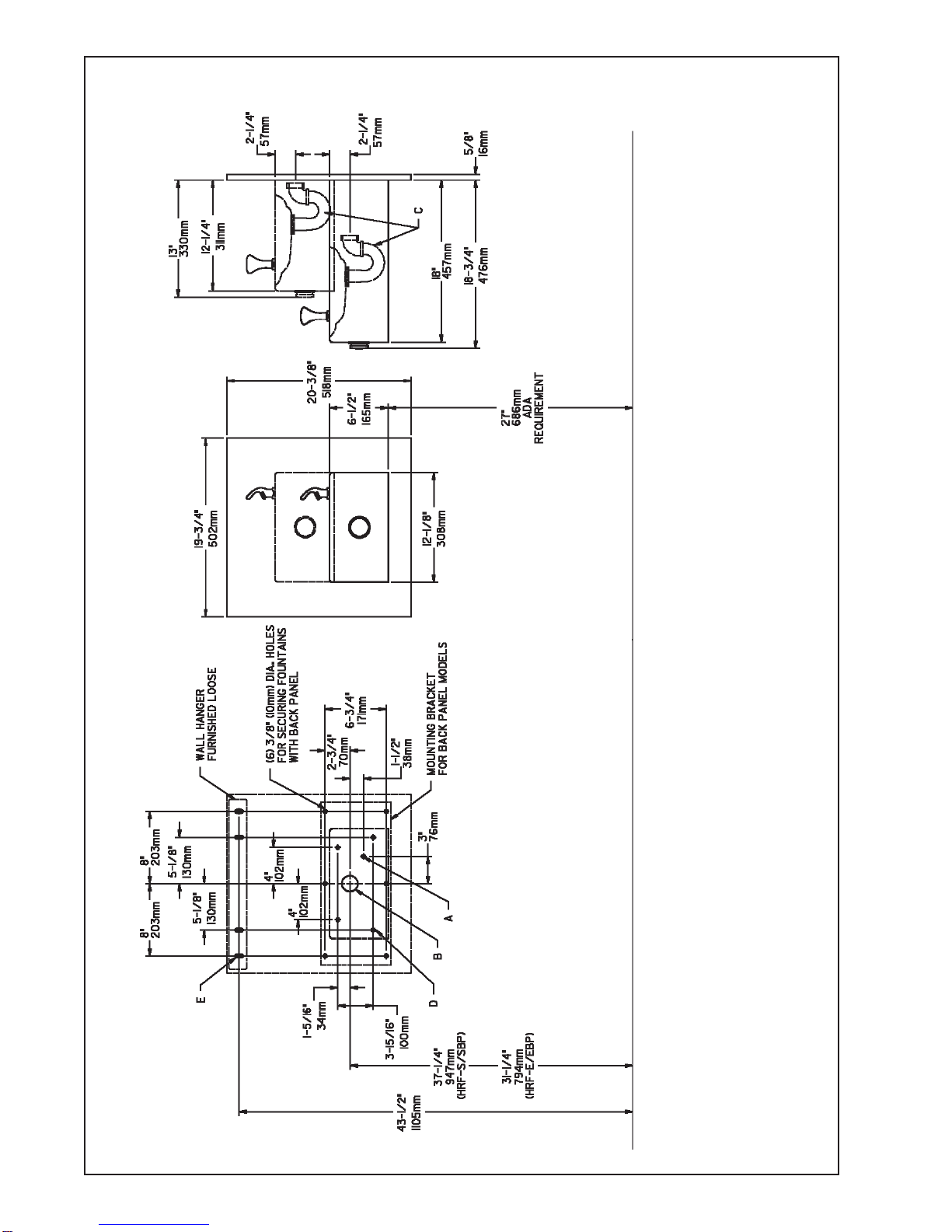
1. Wall should already be framed for the fountain using the positioning dimensions shown in Fig. 3. Shown dimension
pertain to installation location (framing must support up to 150 lbs. weight). These dimensions are required for compliance
with ANSI Standard A117.0.
2. Install rough-in plumbing as shown in Fig. 3. Waste line should extend a minimum of 2" (51mm) thru the back panel. Run
supply water inlet line thru back panel. Install a service stop (not provided). Turn on supply water and flush thoroughly.
3. Remove bottom access panel from fountain basin and save the screws. Install the fountain to the back panel and wall
using (4) 5/16" x 2" lag bolts and washers (not provided) thru holes in back panel. Tighten securely.
4. Cut waste tube to required length using plumbing hardware and trap (not provided) as a guide. Install hardware and
trap. Tighten securely.
5. Make water supply connections from service stop to the fountain strainer (See Fig. 1). Turn on water supply and
check for leaks. Newly installed water supply line should be insulated after leak check is completed. DO NOT SOLDER TUBES
INSERTED INTO THE STRAINERAS DAMAGE TO THE O-RINGS MAY RESULT.
6. These products are designed to operate on 20-105 PSIG supply line pressure. If inlet pressure is above 105 PSIG, a
pressure regulator must be installed in the supply line. Any damage caused by reason of connecting these products to supply
line pressure lower than 20 PSIG or higher than 105 PSIG is not covered by warranty.
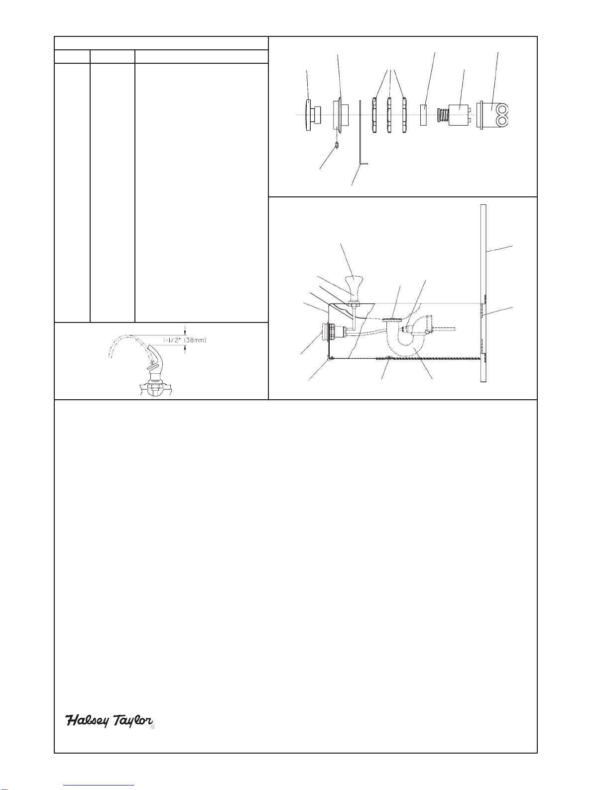
7. Check stream height from bubbler. Stream height is factory set at 45-50 PSI. If supply pressure varies greatly from this,
adjust screw on regulator (Item 9). Clockwise adjustment will raise stream height and counter-clockwise adjustment will
lower stream height. For best adjustment stream height should be approximately 1-1/2" (38mm) above the bubbler guard.
(See Fig. 5).
8. Replace bottom access panel to fountain basin using screws provided. Tighten securely.
FIG. 5
SEE FIG. 5
SEE
FIG. 6
8
15
13
12
1
11,14
3,4
18
FIG. 7
FOR PARTS, CONTACT YOUR LOCAL DISTRIBUTOR OR CALL 1.800.323.0620
2222CAMDEN COURT
OAKBROOK,IL60523
630.574.3500 PRINTEDINU.S.A.
20
19
21