manuals.online logo
Brands
  1. Home
  2. •
  3. Brands
  4. •
  5. Halsey Taylor
  6. •
  7. Water Dispenser
  8. •
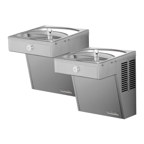
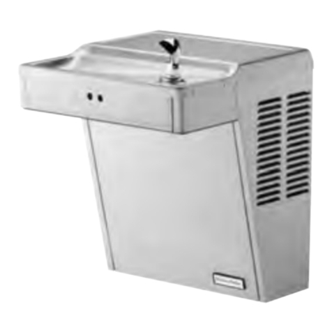
  9. Halsey Taylor HVRBL Series User manual

Halsey Taylor HVRBL Series User manual

Page 1 98953C (Rev. B - 11/16)
HVR8BL(R)*1D HVR8BLWF*1D
Owners Manual
MANUAL DEL PROPIETARIO HALSEY TAYLOR
MANUEL DE L'UTILISATION HALSEY TAYLOR
HVRBL™ Series Vandal-Resistant Water Coolers
Serie HVRBL™ enfriadores de agua a prueba de agresiones
Série HVRBL™ anti-vandalisme refroidisseurs d’eau
All manuals and user guides at all-guides.com
Page 2
98953C (Rev. B - 11/16)
HVR8BL(R)*1D HVR8BLWF*1D
10
20
7
39
6
1
16
3
See Fig. 5
See Fig. 5
25
25
27
38
21
11
19
4
32
37
27
27
5
21
9
33
27 37 8
32
33
21
27
6
16 16
2
1
12
41
See Fig. 5
40
15
21
See Fig. 5
Uses HFC-134A refrigerant
Note: Danger! Electric shock hazard. Disconnect power before servicing unit.
FIG. 1
27
All manuals and user guides at all-guides.com
Page 3 98953C (Rev. B - 11/16)
HVR8BL(R)*1D HVR8BLWF*1D
LEGEND/LEYENDA/LÉGENDE
A = RECOMMENDED WATER SUPPLY LOCATION 3/8 O.D. UNPLATED COPPER TUBE CONNECT STUB WITH SHUT OFF (BY OTHERS) 3 IN. (76mm) MAXIMUM OUT FROM WALL
B = RECOMMENDED LOCATION FOR WASTE OUTLET 1-1/2” O.D. DRAIN STUB 2 IN. OUT FROM WALL
C = 1-1/2” TRAP NOT FURNISHED
D = ELECTRICAL SUPPLY (3) WIRE RECESSED BOX
E = INSURE PROPER VENTILATION BY MAINTAINING 6” (152 mm) (MIN.) CLEARANCE FROM CABINET LOUVERS TO WALL.
F = 7/16 BOLT HOLES FOR FASTENING UNIT TO WALL
FIG. 2
ORIFICE
HEIGHT
ALTURA DEL
ORIFICIO
HAUTEUR DE
L'ORIFICE
ORIFICE
HEIGHT
ALTURA DEL
ORIFICIO
HAUTEUR DE
L'ORIFICE
FINISHED FLOOR
PISO ACABADO
PLANCHER FINI
RIM
HEIGHT
ALTURA DE LA
CORONA
HAUTEUR DU
BORD
C
D
A
B
F25 1/8"
638mm
20 1/8"
511mm
18 3/4"
476mm
13 7/8"
352mm
C
L
C
L
4 1/2"
114mm
3 1/2"
89mm
6 1/4"
158mm
1 1/2"
38mm
10"
254mm
5"
127mm
2 7/16"
63mm
20 3/8"
518mm
37 1/2"
952mm
E
E
F
6 1/2"
166mm
5/16" (8mm) DIA. (10 HOLES)
8mm (10 AGUJEROUS)
8mm (10 TROUS)
18 1/16"
459mm
5 3/4"
146mm
1 3/8"
35mm
5 3/4"
146mm
1 3/8"
35mm
1 3/8"
35mm 1 3/8"
35mm
12 5/16"
312mm
4 1/8"
105mm
8"
203mm
18 5/8"
474mm
27"
686mm
ADA
REQUIREMENT
31 7/8"
810mm
32 15/16"
837mm
39 1/2"
1003mm
2 5/8"
67mm
HANGER BRACKET
FIJADOR DE SUSPENSION
SUPPORT DE SUSPENSION
5 3/4"
146mm 5 3/4"
146mm
6 3/4"
173mm
REDUCE HEIGHT BY 3” FOR INSTALLATION OF CHILDREN’S ADA COOLER
MODEL HVR8BL
All manuals and user guides at all-guides.com
Page 4
98953C (Rev. B - 11/16)
HVR8BL(R)*1D HVR8BLWF*1D
18 5/8"
474mm
HANGER BRACKET
FIJADOR DE SUSPENSION
SUPPORT DE SUSPENSION
2 5/8"
67mm
8"
203mm
4 1/8"
105mm
12 5/16"
312mm
27"
686mm
ADA
REQUIREMENT
31 7/8"
810mm
32 15/16"
837mm
39 1/2"
1003mm
18 1/16"
459mm
5 3/4"
146mm 5 3/4"
146mm
1 3/8"
35mm 1 3/8"
35mm
5 3/4"
146mm 5 3/4"
146mm
1 3/8"
35mm 1 3/8"
35mm
13 7/8"
352mm
18 3/4"
476mm
37 1/2"
952mm
6 1/2"
166mm
20 3/8"
518mm
26 11/16"
677mm
31 11/16"
804mm
2 7/16"
63mm
6 1/4"
158mm
3 1/2"
89mm
4 1/2"
114mm
5"
127mm 10"
254mm
1 1/2"
38mm
FINISHED FLOOR
PISO ACABADO
PLANCHER FINI
C
A
D
E
B
F
F
ORIFICE
HEIGHT
ALTURA DEL
ORIFICIO
HAUTEUR DE
L'ORIFICE
ORIFICE
HEIGHT
ALTURA DEL
ORIFICIO
HAUTEUR DE
L'ORIFICE
RIM
HEIGHT
ALTURA DE LA
CORONA
HAUTEUR DU
BORD
E
5/16" (8mm) DIA. (10 HOLES)
8mm (10 AGUJEROS)
8mm (10 TROUS)
6 3/4"
173mm
LEGEND/LEYENDA/LÉGENDE
A = RECOMMENDED WATER SUPPLY LOCATION 3/8 O.D. UNPLATED COPPER TUBE CONNECT STUB WITH SHUT OFF (BY OTHERS) 3 IN. (76mm) MAXIMUM OUT FROM WALL
B = RECOMMENDED LOCATION FOR WASTE OUTLET 1-1/2” O.D. DRAIN STUB 2 IN. OUT FROM WALL
C = 1-1/2” TRAP NOT FURNISHED
D = ELECTRICAL SUPPLY (3) WIRE RECESSED BOX
E = INSURE PROPER VENTILATION BY MAINTAINING 6” (152 mm) (MIN.) CLEARANCE FROM CABINET LOUVERS TO WALL.
F = 7/16 BOLT HOLES FOR FASTENING UNIT TO WALL
FIG. 3
REDUCE HEIGHT BY 3” FOR INSTALLATION OF CHILDREN’S ADA COOLER
MODEL HVR8BLR
All manuals and user guides at all-guides.com
Page 5 98953C (Rev. B - 11/16)
HVR8BL(R)*1D HVR8BLWF*1D
IMPORTANT
ALL SERVICE TO BE PERFORMED BY AN AUTHORIZED SERVICE PERSON
HANGER BRACKETS & TRAP
INSTALLATION
1) Remove hanger bracket fastened to back of cooler by removing one (1) screw.
2) Mount the hanger bracket and trap as shown in Figure 2.
NOTE: Hanger Bracket MUST be supported securely. Add xture support carrier if wall will not provide adequate support.
IMPORTANT:
• 6 1/4 in. (159mm) dimension from wall to centerline of trap must be maintained for proper t.
• Anchor hanger securely to wall using all ve (5) 1/4 in. dia. mounting holes.
3) Install straight valve for 3/8” O.D. tube.
INSTALLATION OF COOLER
4) Hang the cooler on the hanger bracket. Be certain the hanger bracket is engaged properly in the slots on the cooler back as shown in Figure 2.
5) Loosen the two (2) screws holding the lower front panel at the bottom of cooler base and two (2) screws at the top (Use torx bits sold separately). Remove the front panel and
set aside.
6) Connect water inlet line--See Note 4 of General Instructions.
7) Remove the slip nut and gasket from the trap and install them on the cooler waste line making sure that the end of the waste line ts into the trap. Assemble the slip nut and
gasket to the trap and tighten securely. Recommend fastening cooler to wall using 7/16 bolt holes. (see g.2, “F”)
START UP
Also See General Instructions
8) Stream height is factory set at 45-50 PSI. If supply pressure varies greatly from this, adjust screw using the access hole in the pushbutton (insert screwdriver). CW adjustment
will raise stream and CCW adjustment will lower stream. For best adjustment, stream should hit basin approximately 6-1/2” (165mm) from bubbler.
Fig. 4
Filter Location - When Provided
1
3
22
Fig. 5
Filter - When Provided
DESCRIPCIÓN
ITEM
NO.
1
2
3
55897C
98926C
1000003563
Filtro CPL 1500 galones
Kit - accesorios de cabeza de ltro
Kit - ltro cabeza, soporte, accesorios/
agua-en tubo
DESCRIPTION
PART
NO.
Filtre CPL-1500 gallons
Kit - accessoires de tête de ltre
Kit - ltre tête/support/raccords/eau-en
Tube
DESCRIPTION
WATERSENTRY®FILTER PARTS LIST
(See Fig. 5)
LISTA DE PIEZAS DEL FILTRO
(Vea la Fig. 5)
LISTE DES PIÈCES DU FILTRE
(Voir Fig. 5)
Filter Assy-1500 Gallon
Kit - Filter Head Fittings
Kit - Filter Head/Bracket/
Fittings/Water-In Tube
All manuals and user guides at all-guides.com
Page 6
98953C (Rev. B - 11/16)
HVR8BL(R)*1D HVR8BLWF*1D
Fig. 6
(Refrigerated side shown)
30
14
23
1
27 (8)
25
40 (LH unit)
41 (RH unit)
1
1
22
22
22
33
18
17
17
17
35
36
17
17
13
28
17
28
29 (4)
34
26
27 (6)
31 24
28
32
(Items 31 & 24 also
used on the LH unit)
22
1
1
Basin
VANDAL RESISTANT
BUBBLER DETAIL
All manuals and user guides at all-guides.com
Page 7 98953C (Rev. B - 11/16)
HVR8BL(R)*1D HVR8BLWF*1D
PRINTED IN U.S.A.
2222 CAMDEN COURT
OAK BROOK, IL 60523
630.574.3500
FOR PARTS CONTACT YOUR LOCAL DISTRIBUTOR OR VISIT OUR WEBSITE WWW.HALSEYTAYLOR.COM
97446C
98777C
98775C
36322C
0000000238
75524C
98776C
35839C
98773C
35900C
36012C
55996C
27124C
55931C
160270508640
45876C
56092C
1000001906
98530C
66703C
98724C
70002C
98684C
600985451640
28617C
28963C
22897C
75570C
75661C
70864C
110868642550
28596C
See Color Table
See Color Table
See Color Table
See Color Table
See Color Table
See Color Table
1000001602
1000001994
45929C
45929C
75520C
75523C
28551C
Bubbler Assy - VR
Kit - Compressor Mtg/Clips/Studs/Grommets
Kit - Fan Motor/Blade/Shroud/Nut/Screws
Compressor Serv. Pak
Kit - Relay/Overload/Cover
Clip (Front & Rear Panels)
Kit - Condenser/Drier
Kit - Cold Control/Screws
Kit - Heat Exchanger/Drier
Power Cord (RH Unit)
Power Cord (LH Unit)
Strainer (See “General Instructions”)
Cover - Cold Control
Cover - Dispenser Bottom
Strainer - Bright
Drain Tube Assy.
Tubing - Poly (Cut To length)
Kit - Push Button/Sleeve/Spacer/Nuts/Screw
Kit - Regulator/Holder/Nut
Drier
Evaporator Replacement Assembly
Screw - #10 x 1/2” Lg. HHSM
Kit - Drain Elbow/Gasket/Nut/Washer
Plug - Drain 1-1/2CP
Screen - VR
Basin - Stainless Steel
Panel - Bottom Dispenser
Screw - #10 x .50 Pinned Torx
Screw - #8 x .50 Pinned Torx
Screw - #8 x .62 Torx/Slot
Screw - #10 - 24 x .75 Socket Head
Panel - Screen
Panel - RH Rear
Panel - LH Rear
Panel - RH Dispenser Side
Panel - LH Dispenser Side
Panel - Dispenser Front
Panel - Front Lower
Kit - Elbow 5/16” x 1/4” (3 Pack)
Kit - Tee 1/4” (3 Pack)
Wasteline (LH unit)
Wasteline (Refrig. Unit)
Torx Tool - T25
Torx Tool - T20
Hanger Bracket
PART NO. DESCRIPTION
1
2
3
*4
5
6
7
8
9
10
11
12
13
14
15
16
17
18
19
20
21
22
23
24
25
26
27
28
29
30
31
32
33
34
35
36
37
38
39
40
41
NS
NS
NS
ITEM
NO.
Stainless Steel
PANEL COLOR
COLOR TABLE
Item No. 37
Part No.
Item No. 32
Part No.
Item No. 33
Part No.
Item No. 34
Part No.
Item No. 35
Part No.
Item No. 36
Part No.
28525C 28519C 28516C
28536C 28522C 22955C
Refrig. Unit
Stainless Steel
PANEL COLOR Item No. 37
Part No.
Item No. 32
Part No.
Item No. 33
Part No.
Item No. 34
Part No.
Item No. 35
Part No.
Item No. 36
Part No.
28539C 28519C 28516C
28528C 28522C 22955C
Left Unit COLOR TABLE
Bubbler Assy - VR
Kit - Kit - ojales de clips de los pernos prisioneros
de montaje del compresor
Kit - ventilador Motor/Cuchilla/cubierta/tuerca/tornillos
Compresor Paquete de servicio
Kit - compresor eléctrico/relé/sobrecarga/cubierta
Clip (paneles frontales y posteriores)
Kit - Condensador/Secador
Kit - Control del Enfriamiento/Tornillos
Kit - Intercambiador Térmico/Secador
Cable eléctrico (Unidad de RH)
Cable eléctrico (Unidad de LH)
Filtro (ver “Instrucciones generales”
Portada - Control del frío
Portada - parte inferior del expendedor
Colador - brillante
Conjunto del tubo de drenaje
Tubería de polipropileno (Para cortar al largo)
Kit - pulsador/manga/separador/tuercas/tornillos
Kit - tuerca de soporte de regulador
Secador
Montaje del Kit-Evaporador
Screw - #10 x 1/2” Lg. HHSM
Kit - desagüe Codo/Empaque/Tuerca/Arandela
Enchufe - drenaje 1-1/2CP
Pantalla - resistente al vandalismo
Estanque - Acero inoxidable
Panel - dispensador inferior
Screw - #10 x .50 Pinned Torx
Screw - #8 x .50 Pinned Torx
Screw - #8 x .62 Torx/Slot
Screw - #10 - 24 x .75 Socket Head
Panel - pantalla
Panel - RH trasero
Panel - LH trasero
Panel - lado RH dispensador
Panel - lado LH dispensador
Panel - Dispenser Front
Panel - frontal inferior
Kit - Elbow 5/16” x 1/4” (3 Pack)
Kit - t 1/4”(paquete de 3)
Comprido (unidad de LH)
Comprido (unidad refrigerada)
Torx Tool - T25
Torx Tool - T20
Hanger Bracket
Bubbler Assy - VR
Kit - compresseur montage clips/goujons/oeillets
Kit - ventilateur moteur/lame/carénage/écrou/vis
Kit d’Entretien du Compresseur
Kit-compresseur électrique/relais/surcharge/couvertureClip
Clip (panneaux avant & arrière)
Kit - Condenseur/Séchoir
Kit - Contrôle de Refroidissement/Vis
Kit - Echangeur Thermique/Déshydrateur
Cordon d’Alimentation (Unité de RH)
Cordon d’Alimentation (Unité de LH
Crépine (voir Généralités)
Couverture - contrôle du froid
Couverture - distributeur
Passoire - Bright
Assemblage de Tube de vidange
Poly tube (Ajusté à la longueur souhaitée)
Kit - bouton poussoir/manchon/Spacer/écrous/vis
Kit - régulateur/titulaire/noix
Déshydrateur
Assemblée de L’évaporateur en Kit
Screw - #10 x 1/2” Lg. HHSM
Kit - vidange coude/joint/Écrou/Rondelle
Bouchon - vidange 1-1/2CP
Écran - anti-vandale
Basin - Inox
Panneau - doseur Bottom
Screw - #10 x .50 Pinned Torx
Screw - #8 x .50 Pinned Torx
Screw - #8 x .62 Torx/Slot
Screw - #10 - 24 x .75 Socket Head
Panneau - écran
Panneau - RH arrière
Panneau - LH arrière
Panneau - côté RH distributeur
Panneau - côté LH distributeur
Panel - Dispenser Front
Panneau - bas avant
Kit - coude 5/16 “x 1/4” (Pack de 3)
Kit - Tee 1/4”(Pack de 3)
Wasteline (unité de LH)
Wasteline (Frigidaire)
Torx Tool - T25
Torx Tool - T20
Hanger Bracket
PARTS LIST/ LISTA DE PIEZAS/ LISTE DES PIÈCES
DESCRIPCIÓN DESCRIPTION
*COMPREND RELAIS ET SURCHARGE. SI SOUS GARANTIE, REM-
PLACEZ AVEC LE MÊME SURPRESSEUR QUE CELUI UTILISÉ ORIGI-
NALEMENT.
NOTE: Toute correspondance au sujet des refroidisseurs d’eau courante ou
toute commande de pièce de rechange DOIT inclure le numéro de modèle et
le numéro de série du refroidisseur ainsi que le nom et le numéro de pièce
à remplacer.
*INCLUDES RELAY & OVERLOAD. IF UNDER WARRANTY,
REPLACE WITH SAME COMPRESSOR USED IN ORIGINAL
ASSEMBLY.
NOTE: All correspondence pertaining to any of the above water cool-
ers or orders for repair parts MUST include Model No. and Serial No.
of cooler, name and part number of replacement part.
*INCLUYE RELÉ Y SOBRECARGA. SI ESTÁ BAJO GARANTÍA,
REEMPLACE CON EL MISMO COMPRESOR USADO EN EL
ENSAMBLADO INICIAL.
NOTA: Toda la correspondencia relacionada con el enfriador de agua anterior
o con una orden de reparación piezas DEBERÁ incluir el número de modelo
y número de serie del enfriador, el nombre y número de pieza de la pieza
de repuesto.
All manuals and user guides at all-guides.com

Other Halsey Taylor Water Dispenser manuals

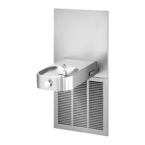
Halsey Taylor OVL User manual

Halsey Taylor

Halsey Taylor OVL User manual

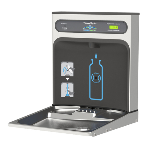
Halsey Taylor HydroBoost HTHBHVR8 Installation manual

Halsey Taylor

Halsey Taylor HydroBoost HTHBHVR8 Installation manual

Halsey Taylor WM8 Series User manual

Halsey Taylor

Halsey Taylor WM8 Series User manual

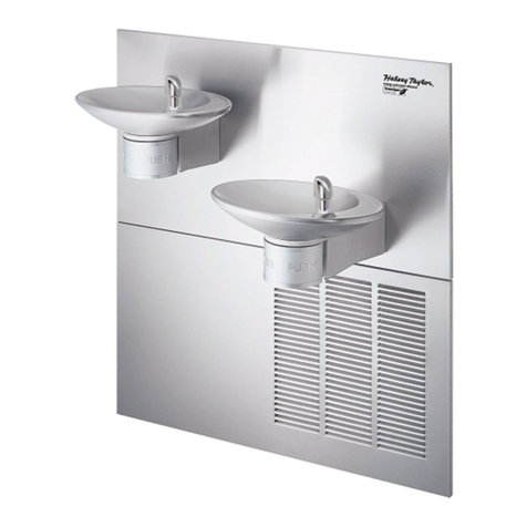
Halsey Taylor HVR Series User manual

Halsey Taylor

Halsey Taylor HVR Series User manual

Halsey Taylor HVR Series User manual

Halsey Taylor

Halsey Taylor HVR Series User manual

Halsey Taylor HydroBoost HTHBHVR8 User manual

Halsey Taylor

Halsey Taylor HydroBoost HTHBHVR8 User manual

Halsey Taylor HAC8EECBL 1E Series User manual

Halsey Taylor

Halsey Taylor HAC8EECBL 1E Series User manual

Halsey Taylor HVRBLFR Series User manual

Halsey Taylor

Halsey Taylor HVRBLFR Series User manual

Halsey Taylor HydroBoost HTHBHACG8BL 1B Series User manual

Halsey Taylor

Halsey Taylor HydroBoost HTHBHACG8BL 1B Series User manual

Halsey Taylor SW8 User manual

Halsey Taylor

Halsey Taylor SW8 User manual

Halsey Taylor HCRF-ER User manual

Halsey Taylor

Halsey Taylor HCRF-ER User manual

Halsey Taylor HVR8HD*1C Series User manual

Halsey Taylor

Halsey Taylor HVR8HD*1C Series User manual

Halsey Taylor HOF14AQ 1F Series User manual

Halsey Taylor

Halsey Taylor HOF14AQ 1F Series User manual

Halsey Taylor HACFSCD C Series User manual

Halsey Taylor

Halsey Taylor HACFSCD C Series User manual

Halsey Taylor HAC4F-Q 1C Series User manual

Halsey Taylor

Halsey Taylor HAC4F-Q 1C Series User manual

Halsey Taylor S300-2D-Q User manual

Halsey Taylor

Halsey Taylor S300-2D-Q User manual

Halsey Taylor GBMAKV*B User manual

Halsey Taylor

Halsey Taylor GBMAKV*B User manual

Halsey Taylor HVRGRN8BL User manual

Halsey Taylor

Halsey Taylor HVRGRN8BL User manual

Halsey Taylor HVRGRN Series User manual

Halsey Taylor

Halsey Taylor HVRGRN Series User manual

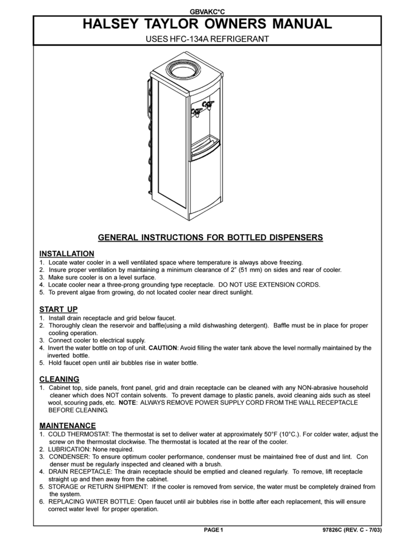
Halsey Taylor GBVAKC*C User manual

Halsey Taylor

Halsey Taylor GBVAKC*C User manual

Halsey Taylor HTVEE Series User manual

Halsey Taylor

Halsey Taylor HTVEE Series User manual

Halsey Taylor HVRBL Series User manual

Halsey Taylor

Halsey Taylor HVRBL Series User manual

Halsey Taylor HAC8EECQ 1E Series User manual

Halsey Taylor

Halsey Taylor HAC8EECQ 1E Series User manual

Halsey Taylor HAC Series User manual

Halsey Taylor

Halsey Taylor HAC Series User manual

Popular Water Dispenser manuals by other brands

EcoWater 7283560 owner's manual

EcoWater

EcoWater 7283560 owner's manual

Elkay EZ Series Installation, care & use manual

Elkay

Elkay EZ Series Installation, care & use manual

CG MERIDIA instruction manual

CG

CG MERIDIA instruction manual

Whirlpool System I instructions

Whirlpool

Whirlpool System I instructions

Honeywell KS10S Installation instruction

Honeywell

Honeywell KS10S Installation instruction

Lancaster diamond 7-LXC-50B Installation, operating and service manual

Lancaster

Lancaster diamond 7-LXC-50B Installation, operating and service manual

Elkay EFY8*1B Installation, care & use manual

Elkay

Elkay EFY8*1B Installation, care & use manual

Vivreau V3-201 Service manual

Vivreau

Vivreau V3-201 Service manual

CSI Twin Series manual

CSI

CSI Twin Series manual

Primo Water T355 Quick Start Guide and Operating Instructions

Primo Water

Primo Water T355 Quick Start Guide and Operating Instructions

Zip Micro BC Installation instructions & user manual

Zip

Zip Micro BC Installation instructions & user manual

Watermark STM1 Installation and operating manual

Watermark

Watermark STM1 Installation and operating manual

Morton M45C Installation and operation manual

Morton

Morton M45C Installation and operation manual

InSinkErator CWT Installation, care & use

InSinkErator

InSinkErator CWT Installation, care & use

Primo Water 900139 user manual

Primo Water

Primo Water 900139 user manual

E&B Giftware Sportline HydraCoach user guide

E&B Giftware

E&B Giftware Sportline HydraCoach user guide

WaterLogic WL900 Troubleshooting

WaterLogic

WaterLogic WL900 Troubleshooting

Thermaltake Pacific RL240 user manual

Thermaltake

Thermaltake Pacific RL240 user manual

manuals.online logo
manuals.online logoBrands
  • About & Mission
  • Contact us
  • Privacy Policy
  • Terms and Conditions

Copyright 2025 Manuals.Online. All Rights Reserved.