Hamamatsu Photonics C9100-02 User manual

Electron Multiplier CCD Camera
C9100-02
Instruction Manual
Thank you for your purchase.
CAUTION
• Follow the safety precautions in Chapter 1 in order to avoid
personal injury and damage to property when using this camera.
The manual describes the correct handling method of C9100
camera and provides cautions in order to avoid accidents. Read
this manual carefully beforehand use the camera correctly.
After reading the manual, store it in a location where you can
refer to it at any time.
Ver. 1.7
April 2007
HAMAMATSU PHOTONICS K.K.
7825172-07

~ Blank page ~

C9100-02 Ver.1.7
1. SAFETY PRECAUTIONS
1-1 CLASSIFICATION OF WARNINGS
We have classified the warning symbols that appear in this operating manual and on the
camera as follows for better comprehension of their meaning. Make sure that you fully
understand them and obey the instructions they contain.
WARNING
Improper handling of the camera without observing these warnings
could lead to serious injury to the user and even death.
CAUTION
Improper handling of the camera without observing these cautions
could lead to personal injury to the user or damage to property.
Note
This symbol indicates a note to help you get the best performance from the
camera. Read the contents of the note carefully to ensure correct and safe use.
Failure to observe one of these notes might impair the performance of the
camera.
This symbol indicates a cautionary item that should be obeyed when handling the
camera. Read the contents carefully to ensure correct and safe use.
This symbol indicates an action that is forbidden.
Read the contents carefully and be sure to obey them.
This symbol indicates a compulsory action or instruction.
Read the contents carefully and be sure to obey them.
1

C9100-02 Ver.1.7
WARNING
Power supply
Use the camera with the voltage indicated on the rating. Using a
different voltage can damage the camera and lead to fire or electric
shock.
Cables
Be careful not to place heavy objects on cables or bend it excessively.
Doing so can damage the cable and lead to fire or electric shock.
Do not attempt to dismantle or modify the camera
Doing so can also lead to damage and even injury, as some internal
components become hot. Only touch parts as indicated in this manual.
Do not allow foreign objects such as combustible substances,
metal objects or water to get inside the camera.
They can damage the camera and lead to fire or electric shock.
If an abnormality occurs,
such as the image suddenly disappearing or a strange noise, smell or
see smoke coming from the camera, stop the power supply
immediately and contact Hamamatsu subsidiary or local distributor.
Never attempt to repair the camera yourself.
2

C9100-02 Ver.1.7
CAUTION
Connecting and disconnecting cables
Always turn off the power before connecting and disconnecting cables.
Affixing the camera
When fitting the camera to a tripod or other fixture, use the screw
(1/4-20UNC) in the center of a camera mount or the threaded sleeve
(M3) about the mount's perimeter. Be careful not to allow the fitting
screw to enter more than 5 mm from the surface of the mount.
Screwing this in excessively may impair normal operation.
Lenses
Be careful not to screw the lens more than 7 mm onto the C-mount of
the camera. Doing so can scratch the protective glass. (Some wide
angle lenses in particular can have a thread of 7 mm or more.)
Shipping precautions
When transporting the camera by truck, ship, airplane, etc., wrap it
securely in packaging material or something similar.
Do not subject the camera to strong shocks
Dropping the camera or other shocks can damage the camera.
Disposal
When disposing of the system, take appropriate measures in
compliance with applicable regulations regarding waste disposal and
correctly dispose of it yourself, or entrust disposal to a licensed
industrial waste disposal company.In any case, be sure to comply
with the regulations in your country, state, region or province to ensure
the system is disposed of legally and correctly.
3

C9100-02 Ver.1.7
2. CHECK THE CONTENTS OF PACKAGE
When you open the package, check that the following items are included before use. If the
contents are incorrect, insufficient, or damaged in any way, contact Hamamatsu
subsidiary or local distributor without attempting to operate the camera.
C9100-02 camera 1
Lens mount cap (attached to the camera) 1
Camera mount 1
C9100-02 instruction manual (this booklet) 1
[Option]
AC adaptor (The accessories: Power supply Cord) A3472-07
Camera cable (5 m) A9189-05
CameraLink interface cable (5 m) A9262-05
Note • The cable listed in option is highly recommended for use with
C9100 the camera. The camera system may not confirm to CE
marking regulation if other type of cable is used with.
3. INSTALLATION
Avoid using or storing this camera in the following places
• Where the ambient temperature might fall below 0 °C or rise above 40 °C
• Where the temperature varies extremely
• In direct sunlight or near a heater
• Where the humidity is 70 % or more or where there is dripping water
• Close to a strong source of magnetism or radio waves
• Where there is vibration
• Where it might come into contact with corrosive gases (such as chlorine or
fluorine)
• Where there is a lot of dust
Do not block ventilation openings
To prevent excessive internal temperature do not wrap cloth around
the equipment while it is in operation. Make sure the blowholes on
the side panels are not blocked. The blowholes must be at least 10
cm from the wall.
4

C9100-02 Ver.1.7
C
Co
on
nt
te
en
nt
ts
s
1. SAFETY PRECAUTIONS............................................................................ 1
1-1 CLASSIFICATION OF WARNINGS....................................................................1
2. CHECK THE CONTENTS OF PACKAGE................................................... 4
3. INSTALLATION........................................................................................... 4
4. OVERVIEW.................................................................................................. 7
5. FEATURES.................................................................................................. 7
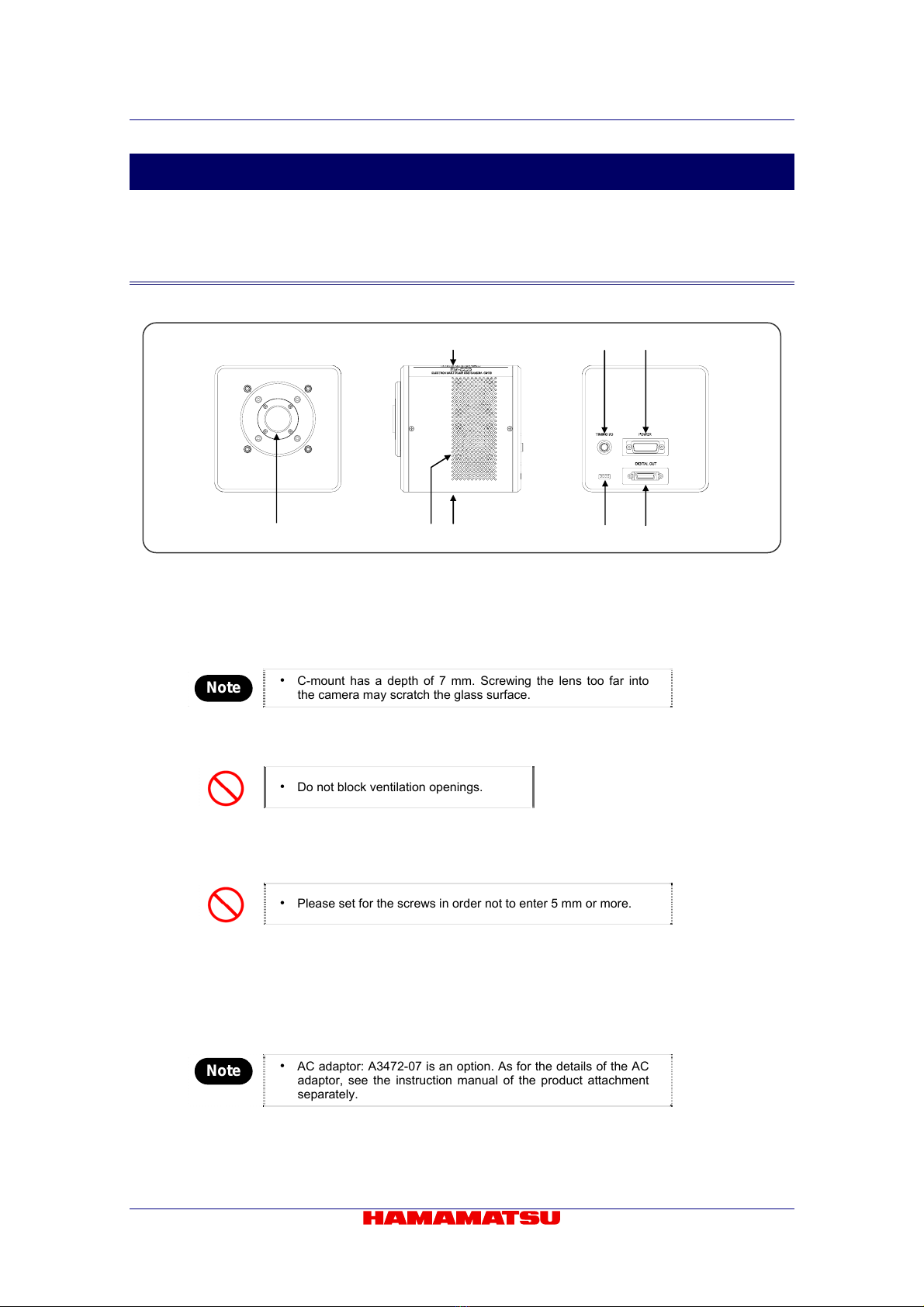
6. NAME AND FUNCTION OF THE PARTS................................................... 8
6-1 CAMERA.............................................................................................................8
7. CONNECTING CABLES ........................................................................... 10
8. OPERATION.............................................................................................. 11
8-1 PREPARATION FOR IMAGING .......................................................................11
8-2 IMAGING...........................................................................................................11
8-3 END OF IMAGING.............................................................................................11
9. IMAGE ACQUISITION............................................................................... 12
9-1 OVERVIEW OF THE CAMERA MODES...........................................................12
9-2 DETAIL OF THE CAMERA MODES.................................................................12
9-2-1 BINNING READOUT AND BINNING SETTINGS VALUES .................................................. 12
10. PRECAUTIONS WHEN USING THE CCD................................................ 13
11. MAINTENANCE ........................................................................................ 14
11-1 CARE.................................................................................................................14
12. TROUBLESHOOTING CHECKLIST......................................................... 15
12-1 IMAGES NOT TRANSFERRED........................................................................15
12-2 ALTHOUGH IMAGES ARE TRANSFERRED...................................................15
12-3 OTHER PROBLEMS.........................................................................................15
13. SPECIFICATIONS..................................................................................... 16
13-1 CAMERA SPECIFICATIONS............................................................................16
13-2 SPECTRAL RESPONSE CHARACTERISTICS ...............................................18
13-3 EM GAIN ...........................................................................................................18
13-4 CAMERALINK INTERFACE SPECIFICATIONS ..............................................19
13-5 TIMING I/O SPECIFICATIONS .........................................................................21
13-5-1 TIMING I/O CONNECTOR PIN ASSIGNMENTS [TIMING I/O] ............................................ 21
13-5-2 TRIGGER IN TIMINGS......................................................................................................... 22
13-5-3 INTEG OUT TIMINGS .......................................................................................................... 24
13-6 POWER SPECIFICATIONS ..............................................................................25
14. DIMENSIONAL OUTLINE......................................................................... 26
5

C9100-02 Ver.1.7
14-1 CAMERA...........................................................................................................26
15. WARRANTY.............................................................................................. 27
16. CONTACT INFORMATION....................................................................... 28
6

C9100-02 Ver.1.7
4. OVERVIEW
Electron Multiplier CCD Camera C9100 series is a new type of high sensitivity CCD camera
that has special structure to get the electric gain on the CCD chip.
C9100 series has resolved the issues like the burning, afterglow, lifetime and low resolution,
comparing to the ICCD camera and EB-CCD camera, and also offered the high sensitivity
images on the similar level to the cameras with real time.
5. FEATURES
(1) High Gain
C9100-02 can amplify the electric charge with approximately 2000 times on the CCD
chip and they can detect the objects that the general normal CCD cameras have not
and offer the images with real time.
(2) Digital output
Image signals are converted from analog to digital in the AC adaptor and output
externally as 14 bit digital data. (Transmission line length: Max.10 m, based on
CameraLink.)
(3) Low image distortion
With the CCD, the pixels are arranged geometrically, virtually eliminating image
distortion. And the image processing can be easily done for the measurement thanks
to square pixels.
(4) No burn-in
The burning, which happens on an ICCD camera with an Image Intensifier, is not
found on the Electron Multiplier CCD camera.
(5) Lens mount
C-mount used for the lens mount.
7

C9100-02 Ver.1.7
6. NAME AND FUNCTION OF THE PARTS
6-1 CAMERA
③④⑤
①②③⑥⑦
Fig.6-1
①Lens mount
C-mount lens or optical system with C-mount can be attached.
Note
• C-mount has a depth of 7 mm. Screwing the lens too far into
the camera may scratch the glass surface.
②Blowhole
The fan circulates the air in order not to increase inside temperature.
• Do not block ventilation openings.
③Screw holes to fix the camera (each four holes on the upside and downside)
When the camera is used with a tripod, the tripod attachment should be attached with
the screw holes.
• Please set for the screws in order not to enter 5 mm or more.
④Timing I/O connector [TIMING I/O]
This connector is used for input and output of timing signals when synchronizing with
external equipment.
⑤Camera connector [POWER]
This is for connecting a camera to an AC adaptor with a camera cable.
Note • AC adaptor: A3472-07 is an option. As for the details of the AC
adaptor, see the instruction manual of the product attachment
separately.
8

C9100-02 Ver.1.7
⑥Mode switching switch
This is a switch for the camera maintenance.
• All positions are set to “OFF”. Do not change this.
⑦CameraLink interface connector [DIGITAL OUT]
Connector used for connecting the camera to the CameraLink interface board.
9

C9100-02 Ver.1.7
7. CONNECTING CABLES
Refer to the figure below when connecting the various cables.
AC adaptor ③Power supply cord
A3472-07 (Option)
Camera
①Camera cable (Option)
PC
②CameraLink interface cable
(Option)
CameraLink interface board
Fig.7-1
• When cables are connected, confirming the power switch is in the OFF position.
①Camera cable (Option: A9189-05)
Camera used for connecting the camera to the AC adaptor.
②CameraLink interface cable (Option: A9262-05)
Cable used for connecting the CameraLink interface connector to the CameraLink
interface board mounted on the host computer.
③Power supply cord (Option: The accessories of A3472-07)
Note • Hamamatsu recommends optional interface for C9100.
- AC adaptor A3472-07
- Camera cable A9189-05
- CameraLink interface cable A9262-05
Depending on type of interface cables, the C9100 may not keep CE marking
compliance in terms of EMC directive.
10

C9100-02 Ver.1.7
8. OPERATION
8-1 PREPARATION FOR IMAGING
Use the following procedure when starting operating of the camera.
(1) Connect the equipment as shown in Figure 7-1 before operating of the
camera.
(2) Switch the AC adaptor's power switch to ON.
(3) After turning the power switch on, wait approximately 30 minutes for the
temperature to stabilize; this completes preparation for imaging.
• Start the measurement after the inside cooling temperature becomes stable
because the Electron Multiplier gain depends on the temperature.
8-2 IMAGING
Switch the power switch to ON.
Digital data output pixel count 1000×1000
Control mode Internal control mode
Scan mode Normal readout
Exposure time setting 32 ms
EM gain Minimum (sensitivity = 0)
Digital data output bit count 14
Commands from the host computer are transmitted via the CameraLink interface, permitting
changes to the modes and parameters.
8-3 END OF IMAGING
(1) End imaging or transmission of image data with the control software when
imaging is finished.
(2) Turn off the power to the peripheral equipment.
Note • Concerning the Beep;
The abnormal high temperature inside the camera makes the beep. Then
turn off the power supply immediately. And turn on the power supply after
removing the factors, which increase the temperature.
11

C9100-02 Ver.1.7
9. IMAGE ACQUISITION
This section describes the modes required when using the camera to obtain images.
9-1 OVERVIEW OF THE CAMERA MODES
This camera features many different operational modes. Furthermore, all modes involve the
CameraLink interface's built-in microprocessor, providing control and setting for all modes.
Of the numerous different modes, the modes used for obtaining images are broadly
classified into the categories below.
(1) Internal control mode
Exposure and readout is performed repeatedly, controlled by the internal
microprocessor. Some operations for which the commands can be used are shown
below.
Scan modes Normal readout/Binning readout/Sub-array readout
Exposure time setting Norma/Frame blanking
(2) External control mode
An external control (trigger) pulse input the internal microprocessor and the
repeating exposure and readout. Exposure start timing and length of exposure can
be controlled with the external trigger pulse. Some operations for which the
commands can be used are shown below. It includes two modes, Edge trigger
mode*1and Level trigger mode*2.
Scan modes Normal readout/Binning readout/Sub-array readout
External control pulse polarity Negative/Positive
* 1 The camera is stand-by and waits for external trigger input when the camera is set in this mode. When the external
trigger signal is input, Electrical charges generated in CCD before the external trigger signal input is dumped out by
High-speed readout. After that, the camera starts the accumulation of the electrical charge until the end of the
exposure time, readout charged electrons and output digital data. The exposure time can be set by the command
operations.
* 2 The camera is stand-by and waits for external trigger input when the camera is set in this mode. When the external
trigger signal is input, Electrical charges generated in CCD before the external trigger signal input is dumped out by
High-speed readout. After that, the camera starts the accumulation of the electrical charge until the end of the
exposure time, readout charged electrons and output digital data. The exposure time can be set by the pulse width
of the external trigger.
9-2 DETAIL OF THE CAMERA MODES
9-2-1 BINNING READOUT AND BINNING SETTINGS VALUES
In addition to the normal readout (1×1 binning readout), in which the digital output pixel
count is read out as is, the following readouts are available.
Binning Commands
2×2 binning readout: 2 horizontal pixels combined with 2 vertical pixels. SMD S SPX 2
4×4 binning readout: 4 horizontal pixels combined with 4 vertical pixels. SMD S SPX 4
8×8 binning readout: 8 horizontal pixels combined with 8 vertical pixels. SMD S SPX 8
16×16 binning readout: 16 horizontal pixels combined with 16 vertical pixels. SMD S SPX 16
12

C9100-02 Ver.1.7
10. PRECAUTIONS WHEN USING THE CCD
C9100 uses a CCD. Read the following points regarding handling of the CCD carefully.
(1) White spots
During long exposure times, imperfection in the CCD’s silicon wafer cause white
spots to be generated on the image. As of the present time, there is no workaround
for this phenomenon. Certain CCD temperature characteristics can cause these
white spots to multiple in relation to exposure time, but using dark subtraction* can
compensate for this phenomenon. Atomic ray may generate white spot.
* After acquiring an image using an arbitrary exposure time, the CCD is placed in a dark state for an equal amount of
time, and reacquires the image without any light exposure. Subsequently, the second image is subtracted from the
first, canceling dark-area information from the original image.
(2) Smear
When imaging very bright objects, bright vertical stripes (vertical smear) may be
visible in the images being taken. This is due to the incident light while transferring
the electrons from sensor part to memory part. The amount of smear is dependent
on (the ratio between) readout time and exposure time. Smear tends to appear more
strongly at shorter exposure time to readout time.
Impact from smear is just a little for the camera in normal mode and frame blanking
mode, but sometimes it is observed when exposure time is shortened to readout
time in external control mode.
(3) Folding distortion
A rough-edged flicker may be visible when imaging striped patterns, lines, and
similar subject matter.
(4) Interference fringes pattern
Coherent light such as LASER light may generate interference fringes pattern on
image.
(5) Electron Multiplier gain (EM gain)
Start the measurement after the inside cooling temperature becomes stable because
the Electron Multiplier gain depends on the temperature. The inside cooling
temperature usually becomes stable after approximately 30 minuets.
When the EM gain is set higher, a part of output signal might show zero. When it is
not good for the measurement, please use with the higher offset level.
(6) EM gain degradation
In order to maintain proper camera performance do not expose the CCD chip to
excessive incident light or excessive EM gain. Turn off power when the C-mount is
exchanged or incident light levels are too high.
This CCD chip has the following characteristics:
1) Higher EM gain creates greater EM gain shift down while maintaining the same
incident light level.
2) Higher incident light levels create greater EM gain shift down while maintaining
the same EM gain setting.
13

C9100-02 Ver.1.7
11. MAINTENANCE
11-1 CARE
Clean the exterior with a soft, dry cloth.
• Do not use a wet cloth, dirty cloth.
14

C9100-02 Ver.1.7
12. TROUBLESHOOTING CHECKLIST
If an abnormality occurs, look up the possible causes in the following tables and, if
necessary, report the details to Hamamatsu subsidiary or local distributor.
12-1 IMAGES NOT TRANSFERRED
Cause Measures Chapter
Cables not fully connected. Reconnect 7
Proper command not transferred to the camera. Reconfirm command
Short in cables. Replace cable
12-2 ALTHOUGH IMAGES ARE TRANSFERRED
(1) Scratches or discoloration visible on the screen
Cause Measures Chapter
Dirty lens. Wipe lens
Front glass of camera dirty. Wipe with gauze dampened with alcohol.
(2) Image is blurred
Cause Measures Chapter
Incorrect back focus. Contact Hamamatsu subsidiary or
distributor. 16
Dirty CCD chip.
(3) Only dark, shaded images output
Cause Measures Chapter
Remove the cap
Lens mount cap left on.
Too little light. Adjust amount of light
Too much light.
EM gain set too low. Adjust gain
EM gain set too high.
(4) All images overflowing
Cause Measures Chapter
Reduce amount of light.
Too much light.
Lower gain
EM gain set too high.
(5) Noise in image
Cause Measures Chapter
Noise introduced from exterior. Find and remedy problem
Poor connection of internal components. Contact Hamamatsu subsidiary or
distributor 16
Bad circuitry.
12-3 OTHER PROBLEMS
(1) Buzzer
Cause Measures Chapter
The blowhole is covered. Do not block ventilation openings
CAUTION • The abnormal high temperature inside the camera makes the beep. Then
turn off the power supply immediately.
15

C9100-02 Ver.1.7
13. SPECIFICATIONS
13-1 CAMERA SPECIFICATIONS
(1) Electrical Specifications
Camera head type Hermetic vacuum-sealed air-cooled head
Imaging device Frame transfer CCD
Effective number of pixels 1000 (H) × 1000 (V)
Cell size 8.0 µm (H) × 8.0 µm (V)
Effective area 8.0 mm (H) × 8.0 mm (V)
Pixel clock rate 35 MHz/pixel
at minimum EM gain 10 electrons *1
Readout noise
(r.m.s.) typ. at maximum EM gain < 1 electron
Full well capacity typ. 70 000 electrons
Minimum EM gain typ. × 6
× 2000 *2
Maximum EM gain typ.
4.4 electrons/ADcounts *3
Circuit gain conversion factor typ.
Forced-air peltier cooling with hermetic sealing*4
Cooling method
Absolute and stabilized to – 50 °C
@ ambient room temperature 0 °C to + 40 °C
Cooling temperature
A/D converter 14 bit
Output Signal / External control CameraLink
Exposure time 100 µs to 10 s
Electronic shutter Yes
Binning Yes
Sub-array Yes
External trigger Yes
Offset enhancement Yes
Contrast enhancement No
Lens mount C-mount
Power requirement DC + 12 V
Power consumption Approx. 60 V・A
* 1 This value is measured in internal control mode, normal readout scan mode, 32 ms exposure time, minimum EM
gain and with no incident light. At first, the standard deviation is calculated from the image, which is made as the
difference of two images taken in these conditions. Then this readout noise is given the result of the calculation
dividing this standard deviation by squire root of 2, multiply it by the circuit gain conversion factor and divided it by
the value of minimum EM gain.
* 2 Even with electron multiplier gain maximum, dark signal is kept low level for low light imaging.
* 3 The circuit gain conversion factor is the calculated value of transformation coefficient, which is used to convert the
measured image count values into the number of electrons on the multiplication register. The EM gain is necessary
to it into the number of electrons in the image area. And the dark subtraction execution is necessary to use the gain
conversion factor for calculation.
* 4 The hermetic sealed head maintains a high degree of vacuum 10-7 to 10-8 Torr, without re-evacuation.
(2) Frame rates
Effective vertical width (Sub-array)
Frame rate of each binning
and sub-array condition 1000 512 256 128 64 32 16
1×1 binning readout 30.1 55.8 101.0 169.8 257.7 347.2 420.2
2×2 binning readout 57.0 101.0 169.8 257.7 347.2 420.2 469.5
4×4 binning readout 103.0 169.8 257.3 347.2 420.2 469.5 500.0
8×8 binning readout 172.7 257.7 347.2 420.2 469.5 500.0 515.5
Frame rate
(frame/s)
16×16 binning readout 262.0 346.0 418.4 467.3 497.5 512.8 520.8
16

C9100-02 Ver.1.7
(3) Operating environment
Ambient operating temperature 0 ºC to + 40 ºC
Ambient storage temperature -10 ºC to + 50 ºC
Ambient operating humidity 70 % or less (no condensation)
Operating space Indoor, altitude up to 2000 m
(4) Dimensional outline and weight
Camera Approx. 2500 g
Note • Please see Chapter 14 Dimensional outline.
(5) Applicable standards
EMC EN61326: 1997 + A1:1998 + A2:2001+ A3:2003 Class A
17

C9100-02 Ver.1.7
13-2 SPECTRAL RESPONSE CHARACTERISTICS
Following is the typical spectral characteristics of the CCD.
0
10
20
30
40
50
60
70
80
400 500 600 700 800 900 1000 1100
QuantumEfficiency(%)
C9100-02TypicalSpectralResponsecharacteristic
WaveLength(nm)
13-3 EM GAIN
Following is the setting value of SENSITIVITY and the typical EM gain.
C9100-02typicalEMGain
1
10
100
1000
10000
0 50 100 150 200 250
Sensitivity
EMGain(times)
18
Table of contents
Other Hamamatsu Photonics Security Camera manuals