REV321-12
WARNING: Failure to read and follow these installation instructions and safety precautions could result in personal injury, equipment damage,
shortened service life or unsatisfactory equipment performance. All information in this document is vital to the proper installation and operation of
the equipment. It is important that all personnel who will be coming in contact with this product thoroughly read and understand this manual.
Turbine
Vibrators
VIBCO
INSTRUCTION MANUAL
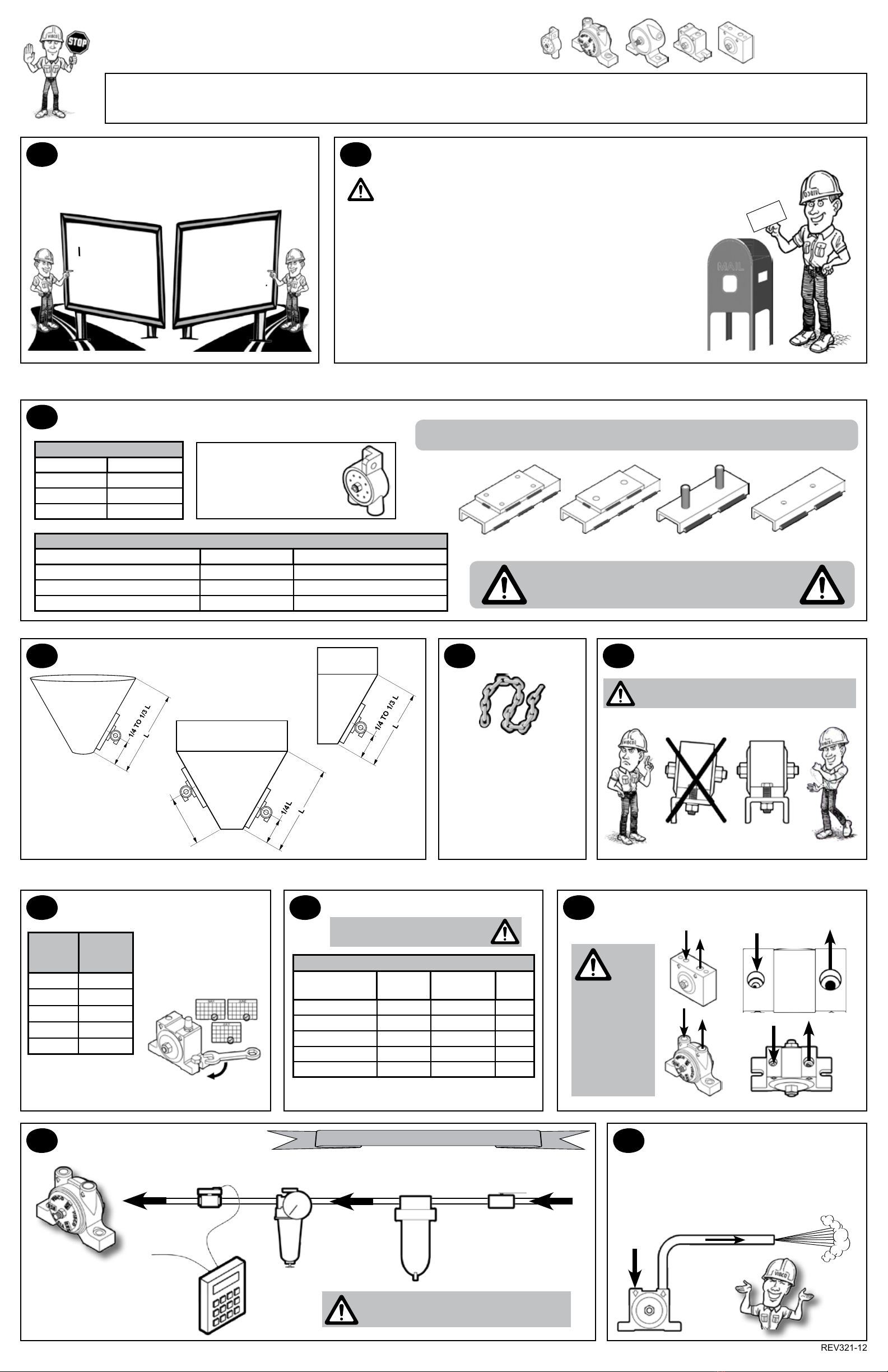
7bolting procedure
MOUNTING PLATES, CHANNEL IRON & ACCESSORIES AVAILABLE FROM VIBCO OR LOCAL DEALER
2mounting instructions checklist
1start
NEW
INSTALLATION
START
HERE!
REPLACEMENT OR
CROSS OVER UNITS
CHECK MOUNTING
AREA BEFORE
REPLACING UNIT.
thank You For choosing
a Vibco Vibrator!
3mounting plates & channel irons
4Vibrator placement 5restraint 6mounting oF Vibrator
8air hose 9input/output
oDetermine length of channel iron.
oSelect thickness of mounting plate & method of mounting.
oSTITCH weld mounting plate to channel iron.
oDetermine vibrator placement on bin.
oSTITCH weld channel iron to bin.
oPlace vibrator on mounting plate.
Check the mounting plate for warping. Secure rmly.
oInstall safety chain or wire.
oConnect pneumatics.
oFILL OUT WARRANTY CARD!!!!
The warranty is void if vibrator is not properly installed. During installation
follow and check off the following steps and your vibrator should provide
you with years of trouble-free service.
WARRANTY
DON’T
FORGET
TO MAIL
IN YOUR
WARRANTY
CARD!
NEVER PLACE VIBRATOR DIRECTLY
ON SKIN OF BIN OR HOPPER!
Drill/tap holes or use studded plate
You must stitch Weld MOUNTING PLATE & CHANNEL IRON!
NEVER CONTINUOUSLY WELD. STOP WELDS 1” FROM ENDS TO PREVENT CRACKING.
CORRECT MOUNTING PLATES
Lbs. of force Plate thickness
Up to 100 lbs. 1/4” plate
100 to 500 lbs. 3/8” to 1/2” plate
over 500 lbs. 1/2” plate
SUGGESTED CHANNEL LENGTH
Lbs. of force/bin wall thickness Channel iron width Channel iron length
up to 100 lbs / bin wall < 3/16” (thin) 3” channel iron 18” to 36” on both sides of vibrator
up to 500 lbs. / bin wall = 3/16” to 1/4” 4” channel iron 3” to 4” on both sides of the vibrator
over 500 lbs / bin wall = 3/8” to 1/2” 4” channel iron 6” to 8” on both sides of the vibrator
Flange style mounting
requires only one bolt to
mount. Mounting locations
will vary depending on
application.
Conical
Bin 1/2
Rectangular
Bin
2 Vibrators On
A Single Bin
THESE ARE JUST
EXAMPLES.
GO ONLINE
www.vibco.com
TO SEE MORE
ALWAYS
INSTALL
SAFETY CHAIN
Mount one end to the vibrator
and the other to the hopper
or bin above the vibrator
NEVER ATTACH CHAIN TO
THE MOUNTING PLATE
DAMAGE TO THE BIN AND THE VIBRATOR
CAN OCCUR IF NOT MOUNTED SECURELY.
Angle Iron Channel Iron
Make sure the vibrator is
secured tightly. Retighten
after the rst 10 -15
minutes of operation &
check them periodically to
maintain proper tightness.
Be sure surfaces are
smooth, at & free of
any debris.
GRADE
5 BOLT
SIZE
MAX
TORQUE
ft-lbs
1/4” 13
5/16” 25
3/8” 48
1/2” 115
5/8” 145
Remember to check
those bolts!
TO DETERMINE CORRECT AIR HOSE SIZE**
TURBINE MODEL
NUMBER
MIN AIR
HOSE DIA
MIN FR*
THREAD DIA CFM
100 - 130 1/8” 1/4” 4 - 6
160 - 250 1/4” 1/4” 7 - 10
320 - 380 3/8” 3/8” 10 - 18
440 - 510 1/2” 1/2” 18 - 21
570 3/4” 3/4” 21 - 30
* F=lter R=regulator
** these specs for installation of single unit;
for multiple units, adjust to maintain CFM
TAPERED THREADS!! DO NOT
OVER TIGHTEN FITTINGS.
On
BVS,
BBS,
MLT & MHI
models, the
smaller INNER
port is the air
inlet and the
larger INNER
port is the
exhaust.
IN OUT
10 pneumatic hook-up 11 air discharge
Timer
Ball
Valve
Air
Filter
Air
Regulator
Solenoid
Valve
To Control
Switch
To
Vibrator
ALL ACCESSORY ITEMS AVAILABLE FROM VIBCO
DO NOT LUBRICATE AIR...NO
LUBRICATION NECESSARY
Clean or Sanitary Environments:
Models BVS, MLT & MHI are equipped with a
threaded exhaust port to allow for exhaust air to
be piped off remotely.


