Hamilton Home Products WGH Manual

THIS MANUAL IS THE PROPERTY OF THE OWNER.
PLEASE BE SURE TO LEAVE IT WITH THE OWNER WHEN YOU LEAVE THE JOB.
Inspection on Arrival
1. Inspect unit upon arrival. .
2.
Check rating plate on unit to verify that power supply meets
available electric power at the point of installation.
3. Inspect unit upon arrival for conformance with description of
product ordered (including specifications where applicable).
For technical assistance and Warranty Administration,
contact Hamilton Home Products at 1.800.879.0123. Do not
return equipment to the home center.
Table of Contents
Inspection on Arrival . . . . . . . . . . . . . . . . . . . . . . . . . . . . . . . . .1
Special Precautions . . . . . . . . . . . . . . . . . . . . . . . . . . . . . . . . . .2
SI (Metric) Conversion Factors . . . . . . . . . . . . . . . . . . . . . . . . .3
Unit Location . . . . . . . . . . . . . . . . . . . . . . . . . . . . . . . . . . . . . . .3
Combustible Material and Service Clearances . . . . . . . . .3
Unit Mounting . . . . . . . . . . . . . . . . . . . . . . . . . . . . . . . . . . .4
Unit Installation . . . . . . . . . . . . . . . . . . . . . . . . . . . . . . . . . . . . .6
Venting . . . . . . . . . . . . . . . . . . . . . . . . . . . . . . . . . . . . . . . .5
Gas Connections . . . . . . . . . . . . . . . . . . . . . . . . . . . . . . .10
Electrical Connections . . . . . . . . . . . . . . . . . . . . . . . . . . .11
Checking Input Rate . . . . . . . . . . . . . . . . . . . . . . . . . . . . .12
Unit Components . . . . . . . . . . . . . . . . . . . . . . . . . . . . . . . . . . .14
Dimensions . . . . . . . . . . . . . . . . . . . . . . . . . . . . . . . . . . . . . . .16
Service/Trouble Shooting . . . . . . . . . . . . . . . . . . . . . . . . . . . .17
Wiring . . . . . . . . . . . . . . . . . . . . . . . . . . . . . . . . . . . . . . . . . . .21
Warranty . . . . . . . . . . . . . . . . . . . . . . . . . . . . . . . . . . . . . . . . .35
INSTALLATION AND SERVICE MANUAL
gas-fired unit heaters
model WGH
VHHP6-576.5
Part 5H76253 Rev. E
March, 2004
All models approved for use in California by the CEC, in New
York by the MEA division, and in Massachusetts. Unit heater
is certified for residential and commercial applications.
WARNING
Improper installation, adjustment, alteration,
service or maintenance can cause property
damage, injury or death, and could cause
exposure to substances which have been
determined by various state agencies to cause
cancer, birth defects or other reproductive
harm. Read the installation, operating and
maintenance instructions thoroughly before
installing or servicing this equipment.
FOR YOUR SAFETY
The use and storage of gasoline or other
flammable vapors and liquids in open
containers in the vicinity of this appliance
is hazardous.
CAUTION
To prevent premature heat exchanger failure
do not locate ANY gas-fired units in areas
where chlorinated, halogenated or acid
vapors are present in the atmosphere.
FOR YOUR SAFETY
WHAT TO DO IF YOU SMELL GAS:
1. Open windows.
2. Do not try to light any appliance.
3. Do not touch any electrical switch; do not
use any phone in your building.
4. Immediately call your gas supplier from
a neighbor’s phone. Follow the gas
supplier’s instructions. If you can not reach
your gas supplier, call your fire department.
IMPORTANT
The use of this manual is specifically
intended for a qualified installation and
service agency. All installation and service
of these units must be performed by a
qualified installation and service agency.
Hamilton Home Products, Inc.

SPECIAL PRECAUTIONS/TABLE OF CONTENTS
2
SPECIAL PRECAUTIONS
THE INSTALLATION AND MAINTENANCE INSTRUCTIONS IN THIS
MANUAL MUST BE FOLLOWED TO PROVIDE SAFE, EFFICIENT
AND TROUBLE-FREE OPERATION. IN ADDITION, PARTICULAR
CARE MUST BE EXERCISED REGARDING THE SPECIAL
PRECAUTIONS LISTED BELOW. FAILURE TO PROPERLY
ADDRESS THESE CRITICAL AREAS COULD RESULT IN PROPERTY
DAMAGE OR LOSS, PERSONAL INJURY, OR DEATH. THESE
INSTRUCTIONS SUBJECT TO ANY MORE RESTRICTIVE LOCAL OR
NATIONAL CODES.
HAZARD INTENSITY LEVELS
1. DANGER: Indicates an imminently hazardous situation
which, if not avoided, WILL result in death or serious injury.
2. WARNING: Indicates a potentially hazardous situation
which, if not avoided, COULD result in death or serious injury.
3. CAUTION: Indicates a potentially hazardous situation which,
if not avoided, MAY result in minor or moderate injury.
4. IMPORTANT: Indicates a situation which, if not avoided,
MAY result in a potential safety concern.
DANGER
Appliances must not be installed where they may be exposed
to a potentially explosive or flammable atmosphere.
WARNING
1. Gas fired heating equipment must be vented - do not
operate unvented.
2. A built-in power exhauster is provided - additional external
power exhausters are not required or permitted.
3. All field gas piping must be pressure/leak tested prior to
operation. Never use an open flame. Use a soap solution
or equivalent for testing.
4. Gas pressure to appliance controls must never exceed 14"
W.C. (1/2 psi).
5. Disconnect power supply before making wiring connections
to prevent electrical shock and equipment damage.
6. All appliances must be wired strictly in accordance with
wiring diagram furnished with the appliance. Any wiring
different from the wiring diagram could result in a hazard to
persons and property.
7. Any original factory wiring that requires replacement must
be replaced with wiring material having a temperature
rating of at least 105°C.
8. When servicing or repairing this equipment, use only
factory-approved service replacement parts. A complete
replacements parts list may be obtained by contacting
the factory. Refer to the rating plate on the appliance for
complete appliance model number, serial number, and
company address. Any substitution of parts or controls not
approved by the factory will be at the owners risk.
9. If you are replacing an existing heater, it may be necessary
to resize the venting systems. Improperly sized venting
systems can result in vent gas leakage or the formation of
condensate. Refer to the National Fuel Gas Code ANSI
Z223.1 or CAN/CGA B149.1 or .2 latest edition. Failure to
follow these instructions can result in injury or death.
10. To reduce the opportunity for condensation, the minimum
sea level input to the appliance, as indicated on the serial
plate, must not be less than 5% below the rated input, or
5% below the minimum rated input of duel rated units.
11. Ensure that the supply voltage to the appliance, as
indicated on the serial plate, is not 5% greater than the
rated voltage.
CAUTION
1. Installation must conform with local building codes or in the
absence of local codes, with Part 7, Venting of Equipment,
of the National Fuel Gas Code, ANSI Z223.1 (NFPA 54) -
latest edition. In Canada installation must be in accordance
with CAN/CGA-B149.1 for natural gas units, and
CAN/CGA-B149.2 for propane units.
2. Consult piping, electrical, and venting instructions in this
manual before final installation.
3. Turn off all gas before installing appliance.
4. Do not locate units in tightly sealed rooms or small
compartments (commonly referred to as confined spaces)
without provisions for adequate combustion air and venting.
Combustion air must have access to the confined space
through a minimum of two permanent openings in the
enclosure, at least one near the bottom. They should
provide a free area of one square inch per 10,000 BTU/Hr
input rating of the unit with a minimum of 100 square inches
for each opening, whichever is greater.
5. When leak testing the gas supply piping system, the
appliance and its combination gas control must be isolated
during any pressure testing in excess of 14" W.C. (1/2 psi).
6. Check the gas inlet pressure at the unit upstream of the
combination gas control. The inlet pressure should be 6-7"
W.C. on natural gas or 12-14" W.C. on propane. If inlet
pressure is too high, install an additional pressure regulator
upstream of the combination gas control.
7. Purging of air from gas supply line should be performed as
described in ANSI Z223.1 - latest edition “National Fuel
Gas Code”, or in Canada in CAN/CGA-B149 codes.
8. The minimum distance from combustible material is based
on the combustible material surface not exceeding 160°F.
Clearance from the top of the unit may be required to be
greater then the minimum specified if heat damage, other
than fire, may occur to materials above the unit heater at
the temperature described.
9. Do not attempt to reuse any mechanical or electronic
ignition controllers which has been wet. Replace defective
controller.
10. Do not install unit outdoors.
11. Servicing or repairing of this equipment must be performed
by a qualified service agency.
12. Do not install units below 7' measured from the bottom of
the unit to the floor in commercial applications and 5'
measured from the bottom of the unit to the floor in
residential applications.
13. Be sure no obstructions block air intake and discharge of
unit heaters.
14. Allow 18" of clearance at rear (or 6" beyond end of motor at
rear of unit, whichever is greater) and access side to
provide ample air for combustion and proper operation of fan.
15. Installation of units in high humidity or salt water
atmospheres will cause accelerated corrosion resulting in a
reduction of the normal life of the units.
16. The unit should be isolated from the gas supply piping
system by closing its field installed manual shut-off valve.
This manual shut-off valve should be located within 6' of
the heater.
17. In aircraft hangars, keep the bottom of the unit at least 10'
from the highest surface of the wings of engine enclosure
of the highest aircraft housed in the hangars and in
accordance with the requirements of the enforcing authority
and/or NFPA 409-latest edition.

33
SI (METRIC) CONVERSION FACTORS
Table 3.1
GENERAL
In the U.S., the installation of these units must comply with the
“National Fuel Gas Code,” ANSI Z223.1, latest edition (also
known as NFPA 54) and other applicable local building codes.
In Canada, the installation of these units must comply with local
plumbing or waste water codes and other applicable codes and
with the current code CAN/CGA-B149.1 “Installation Code for
Natural Gas Burning Appliances and Equipment” or CAN/CGA-
B149.2, “Installation Code for Propane Burning Appliances and
Equipment.”
1. All installation and service of these units must be
performed by a qualified installation and service agency
only as defined in ANSI Z223.1, latest edition or in Canada
by a licensed gas fitter.
2. This unit is certified with the controls furnished. For
replacements parts, please order according to the
replacement parts list on serial plate. Always know your
model and serial numbers. The right is reserved to
substitute other authorized controls as replacements.
3. Unit is balanced for correct performance. Do not alter fan
or operate motors at reduced speed.
4. Information on controls is supplied separately.
5. The same burner is used for natural and propane gas.
UNIT LOCATION
Location Recommendations
1. When locating the furnace, consider general space and
heating requirements, availability of gas and electrical
supply, and proximity to vent locations.
2. When locating units, it is important to consider that the
exhaust vent piping must be connected to the outside
atmosphere.
SPECIAL PRECAUTIONS / SI (METRIC) CONVERSION FACTORS / UNIT LOCATION
CAUTION
1. Do not locate units in tightly sealed rooms or small
compartments (commonly referred to as confined spaces)
without provisions for adequate combustion air and
venting. Combustion air must have access to the confined
space through a minimum of two permanent openings in
the enclosure, at least one near the bottom. They should
provide a free area of one square inch per 10,000 BTU/Hr
input rating of the unit with a minimum of 100 square
inches for each opening, whichever is greater.
2. Low profile heaters are designed for use in heating
applications with ambient temperatures between -40°F
and 90° F.
3. Do not install unit outdoors.
4. In commercial garages or other sections of aircraft hangars
such as offices and shops which communicate with areas
used for servicing or storage, keep the bottom of the unit
at least 7' above the floor. In public garages, the unit must
be installed in accordance with the Standard for Parking
Structures NFPA 88A and the Standard for Repair Garages
NFPA 88B. In Canada, installation of unit heater in airplane
hangars must be in accordance with the requirements of the
enforcing authority, and in public garages in accordance with
the current CAN/CGA-B149. codes.
5. In aircraft hangars, keep the bottom of the unit at least 10'
from the highest surface of the wings or engine enclosure
of the highest aircraft housed in the hangars and in
accordance with the requirements of the enforcing authority
and/or NFPA 409-latest edition.
6. Installation of units in high humidity or salt water atmospheres
will cause accelerated corrosion resulting in a reduction of
the normal life of the units.
DANGER
Appliances must not be installed where they may be exposed
to a potentially explosive or flammable atmosphere.
To Convert Multiply By To Obtain
"W.C. 0.24 kPa
psig 6.893 kPa
°F (°F-32) x 0.555 °C
inches 25.4 mm
feet 0.305 meters
CFM 0.028 m3/min
To Convert Multiply By To Obtain
CFH 1.699 m3/min
Btu/ft30.0374 mJ/m3
pound 0.453 kg
Btu/hr 0.000293 kW/hr
gallons 3.785 liters
psig 27.7 "W.C.
CAUTION
1. All literature shipped with this unit should be kept for future
use for servicing or service diagnostics. Do not discard
any literature shipped with this unit.
2. Consult piping, electrical, and venting instructions in this
manual before final installation.
3. Do not attach ductwork, air filters, or polytubes to any
propeller unit heater.
CAUTION
18. In commercial garages or other sections of aircraft hangars
such as offices and shops which communicate with areas
used for servicing or storage, keep the bottom of the unit
at least 7' above the floor. In public garages, the unit must
be installed in accordance with the Standard for Parking
Structures NFPA 88A and the Standard for Repair Garages
NFPA 88B. In Canada, installation of unit heater in airplane
hangars must be in accordance with the requirements of
the enforcing authority, and in public garages in
accordance with the current CAN/CGA-B149 codes.
19. Low profile heaters are designed for use in heating
applications with ambient temperatures between -40°F
and 90°F.
20. All literature shipped with this unit should be kept for
future use for servicing or service diagnostics. Do not
discard any literature shipped with this unit.
21. Ensure that the supply voltage to the appliance, as
indicated on the serial plate, is not 5% less than the rated
voltage.
IMPORTANT
1. To prevent premature heat exchanger failure, do not locate
ANY gas-fired appliances in areas where corrosive vapors
(i.e. chlorinated, halogenated or acid) are present in the
atmosphere.
2. To prevent premature heat exchanger failure, the input to
the appliance as indicated on the serial plate, must not
exceed the rated input by more then 5%.
IMPORTANT
To prevent premature heat exchanger failure, do not locate
ANY gas-fired appliances in areas where corrosive vapors
(i.e. chlorinated, halogenated or acid) are present in the
atmosphere.

3. Be sure the structural support at the unit location site is
adequate to support the weight of the unit. For proper
operation the unit must be installed in a level horizontal
position.
4. Do not install units in locations where the flue products can
be drawn into the adjacent building openings such as
windows, fresh air intakes, etc.
5. Be sure that the minimum clearances to combustible
materials and recommended service clearances are
maintained. Units are designed for installation with the
minimum clearances below:
Top and bottom 1" Non-Access Side 1"
Vent Connector 4" Rear 18"
Access Side 18"
6. Do not install units in locations where gas ignition system is
exposed to water spray, rain, or dripping water.
7. Mounting Height (measured from bottom of unit) at which unit
heaters are installed is critical. Refer to mounting height
information and heat throw data on page 16 of this manual.
The maximum mounting height for any unit is that height
above which the unit will not deliver heated air to the floor.
Combustion Air Requirements
The National Fuel Gas Code defines an “unconfined space” as
a space whose volume is greater than 50 cubic feet per 1,000
Btu/Hr input of the installed appliance(s). A confined space is 50
cubic feet or less per 1,000 Btu/Hr input of the installed
appliance(s).
It is not recommended to install these unit heaters into residential
confined spaces. This recommendation is due to the concern
that at some point in time, the combustion air openings provided
by the installer may become blocked or eliminated by the owner,
either intentionally or unintentionally. Despite this commendation,
if these units are installed into a residential confined space, see
National Fuel Gas Code ANSI Z223.1 or CAN/CGA B149.1 or .2
Installation Code, latest edition, for detailed combustion air
provisions. These requirements must be adheard to.
Units installed into confined spaces in industrial/commercial
installations, must be provided with two permanent openings,
one near the top of the confined space and one near the bottom
of the confined space. Each opening should have a free area of
not less than one square inch per 1,000 BTU per hour of the total
input rating of all units in the confined space, freely
communicating with interior areas having, in turn, adequate
infiltration from the outside.
For further details on supplying combustion or to a confined
(tightly sealed) space or unconfined space, see the National Fuel
Gas Code ANSI Z223.1 or CAN/CGA B149.1 or .2 Installation
Code, latest edition.
Turning The Unit 180°
All units are produced at the factory with left-side controls, when
looking at the unit. If the installation requires that the controls be
on the right side, the unit heater can be “turned over”. In addition,
the following instructions must be followed:
• By turning the unit 180° from the way it was received from
the factory, the sides become opposite but the front and
back remain in the same relative position. The bottom panel
now becomes the top panel and vice-versa.
• Remove the access panel, turn it 180°, and re-attach it to
the unit. This is important so that all the information labels
can be read.
• Remove the spring loaded deflector blades, turn them over,
replace, and adjust so they are open and in a position to
direct the heated air down to the floor.
1. Be sure the means of suspension is adequate to support
the weight of the unit (see page 16 for unit weights).
2. For proper operation, the unit must be installed in a level
horizontal position.
3. Clearances to combustibles as previously specified must be
strictly maintained.
4. Mounting bracket installation:
Before lifting the heater for suspension, the mounting
brackets must be installed. Decide if the unit will be
installed as standard; that is with left-side controls when
looking at the front of the unit or with right-side controls.
For standard (left side)remove brackets from shipping
position and remove the (3) screws along the top edge of
both the front and back of unit. Align screw holes on
mounting bracket with holes along front and back top
edges. Secure (1) mounting bracket to front of unit with
retained screws. Secure the other mounting bracket to back
of unit in a similar way.
For right-hand, the mounting brackets are attached in a
similar manner after the unit is turned over.
5a. Suspension by screws/lag bolts:
Secure the mounting brackets to the ceiling joists or truss,
using 1/4" screws with 1/2" washers. These 1" - angle,
mounting brackets are slotted to accommodate joists on 16"
or 24" centerlines.
5b. Suspension by threaded rod:
This heater can also be hung utilizing the same mounting
brackets and threaded rod. Attach the threaded rod to the
unit mounting brackets, securing with a top and bottom nut.
Next, drill holes into a steel channel or angle iron at the
same centerline dimensions as those chosen for the heater
that is being installed. The steel channels or angle iron
pieces need to span and be fastened to appropriate
structural members. Cut the threaded rods to the preferred
length, push them through the holes in the steel channel or
angle iron and secure with washers and lock nuts, lock
washers and nuts, or a double nut arrangement like used on
the unit heater mounting brackets.
5c. Shelf mounted units:
The unit heater can also be installed on a shelf, if so
desired. The mounting brackets will need to be attached to
the heater the same manner as explained earlier, however,
to mount on a shelf the brackets must go on the bottom of
the heater. The brackets must be affixed to the shelf using
similar screws (1/4" screw with 1/2" washer) as overhead
joist or truss mounting. Be sure all clearance to combustible
requirements are met.
4
CAUTION
1. Do not install units below 7' measured from the bottom
of the unit to the floor in commercial applications and 5'
measured from the bottom of the unit to the floor in
residential applications.
2. Be sure no obstructions block air intake and discharge
of unit heaters.
3. The minimum distance from combustible material is
based on the combustible material surface not
exceeding 160°F. Clearance from the top of the unit
may be requited to be greater than the minimum
specified if heat damage, other than fire, may occur to
materials above the unit heater at the temperature
described.
4. Allow 18" clearance at rear (or 6" beyond end of motor
at rear of unit, whichever is greater) and access side to
provide ample air for combustion and proper operation
of fan.
UNIT LOCATION / UNIT MOUNTING UNIT SUSPENSION

Before you start use the following steps to verify
that the venting system is adequately sized:
1. Seal any unused openings in the venting system.
2. Inspect the venting system for proper size and horizontal
pitch, as required in the National Fuel Gas Code ANSI
Z223.1 or CAN/CGA B149.1 or .2 Installation Code-latest
edition and these instructions. Determine that there is no
blockage or restriction, leakage, corrosion and other
deficiencies, which could cause an unsafe condition.
3. In so far as practical, close all building doors and windows
and all doors between the space in which the appliance(s)
connected to the venting system are located and other
spaces of the building. Turn on clothes dryers and any
exhaust fans such as range hoods and bathroom exhausts,
so they shall operate at maximum speed. Do not operate a
summer exhaust fan. Close fireplace dampers.
4. Follow the lighting instructions. Place the appliance being
inspected in operation. Adjust thermostat so that the
appliance will operate continuously.
5. After it has been determined that each appliance connected
to the venting system properly vents when tested as
outlined above, return doors, windows, exhaust fans,
fireplace dampers and any other gas-burning appliance to
their previous conditions of use.
6. If improper venting is observed during any of the above
tests, the venting system must be corrected.
Note: A vent is the vertical passageway used to convey flue
gases from the unit or the vent connector to the outside
atmosphere. A vent connector is the pipe which connects the
unit to a vent or chimney. Vent connectors serving Category I
appliances shall not be connected into any portion of mechanical
draft systems operating under positive pressure.
Venting Instructions
1. All vertically vented heaters are category I venting.
All horizontally vented heaters are category I or III
depending on venting. For a unit to be classified vertical,
the horizontal run may not exceed 75% of the vertical rise.
2. Using Table 5.1, determine the venting requirements for the
category determined above. A category III heater must
conform to the venting requirements called out in Table 5.1,
which are detailed in the following sections, as well as
additional requirements also detailed in following sections.
3. Vertically vented heaters may be vented with either single
wall or double wall vent pipe. Follow the double wall
manufacturers clearances to combustibles.
4. All heaters come with a factory installed 3" vent adapter for
attaching the vent pipe to the heater. Attach the vent pipe to
the adapter with 3 non-corrosive screws. (Drill pilot holes
through the vent pipe and adapter prior to screwing in place)
5. Do not use any vent pipe smaller than 3". Refer to the
National Fuel Gas Code for the minimum material thickness.
6. A minimum of 12" straight pipe is recommended from the
power exhauster outlet before turns in the vent system.
Suspend horizontal runs at a minimum of 3' intervals.
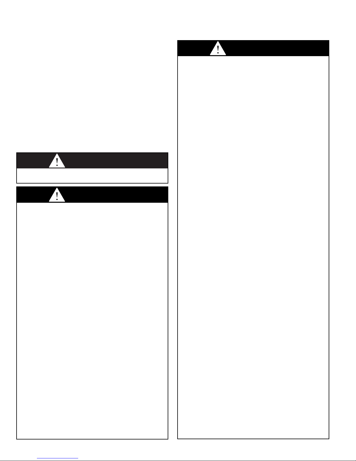
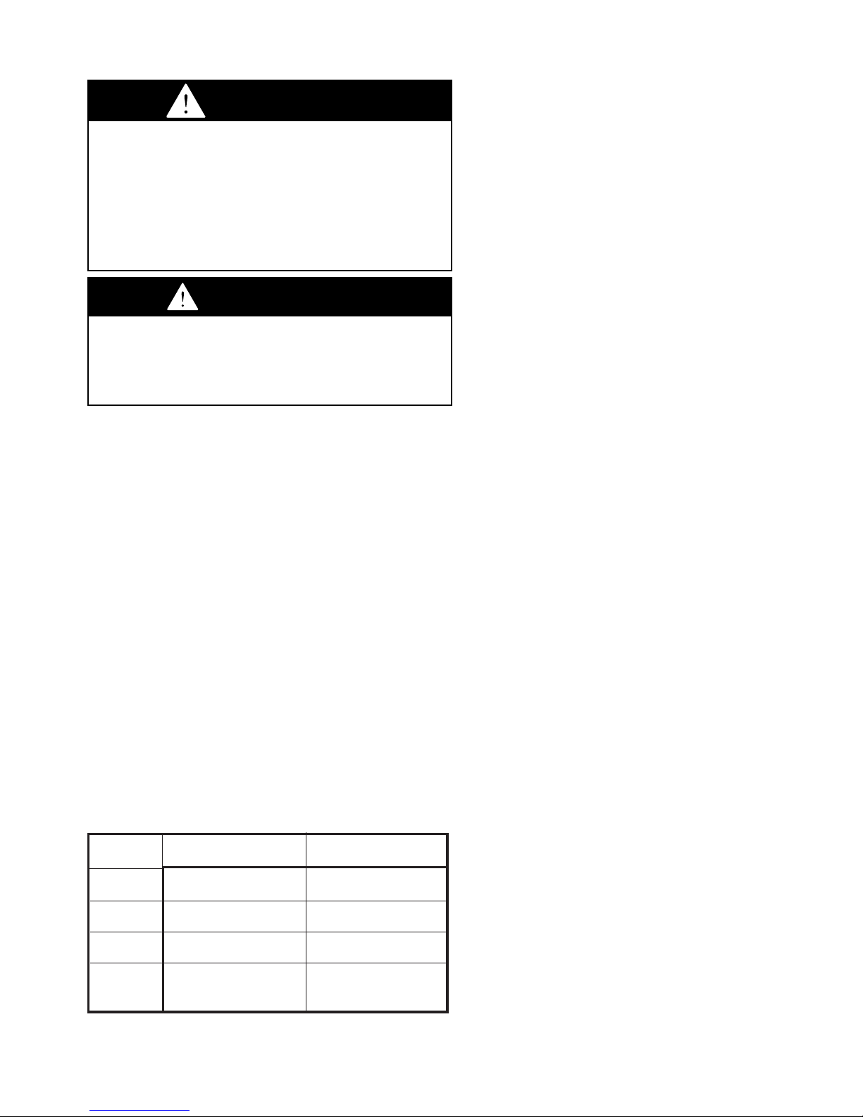
7. Avoid venting through unheated spaces when possible.
When single wall pipe does pass through an unheated
space, insulate runs greater than 5' to minimize
condensation. Inspect for leakage prior to insulating and
use insulation that is noncombustible with a rating of not
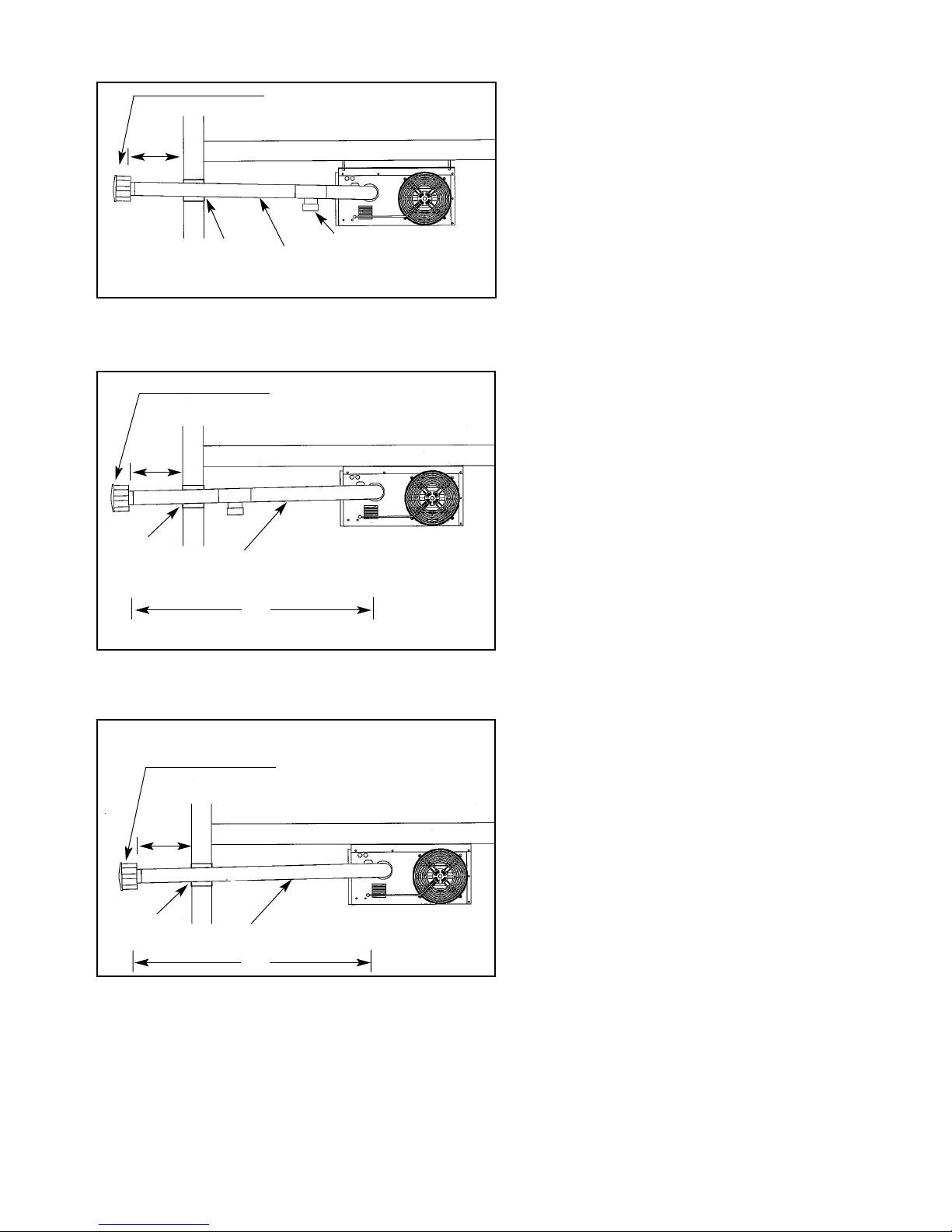
less 350°F. Install a tee fitting at the low point of the vent
system and provide a drip leg with a cleanout cap as
shown in Figures 6.2 and 6.3. The drip leg should be
cleaned annually.
8. Keep single wall vent pipe at least 6" from combustible
material. The minimum distance from combustible material
is based on the combustible material surface not exceeding
160°F. Clearances from the vent pipe (or top of the unit)
may be required to be greater than the minimum clearance
if heat damage (such as material distortion or discoloration)
may occur.
9. When a single wall vent passes through a combustible wall
or floor, a listed thimble must be used. When a type B
double wall vent passes through a combustible wall or floor,
follow the vent pipe manufacturers clearances to
combustibles. Refer to Figure 6.1.
10. This heater is equipped with a power exhaust system.
DO NOT use any additional power exhaust systems or vent
dampers. FAILURE TO FOLLOW THESE INSTRUCTIONS
could result in serious injury or death.
11. All vertically vented heaters are category I and must be
connected to a factory built chimney or vent complying with
a recognized standard, or a masonry (or concrete) lined
chimney with a material acceptable to the authority having
jurisdiction. Venting into an unlined masonry chimney is
not permitted. Refer to the National Fuel Gas Code for
common venting.
12. Secure all vent joints with at least 3 corrosion-resistant
screws. Use an approved vent terminal to reduce down
drafts and moisture in the vent.
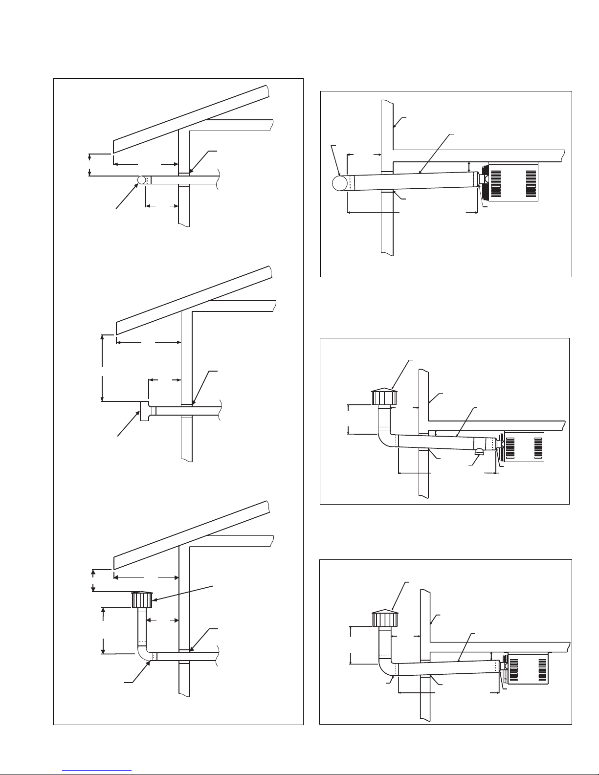
13. The vent must terminate no less than 5' above the vent
connector. The top of the vertical stack should extend
above any portion of a building within a horizontal distance
of 2' (see Figure 6.2).
14. The outlet of the vent should extend as shown in Figure
6.3 and Table 6.1 if the following conditions are met:
Vent diameter is less than 12 inches, vent is of double wall
construction and is a listed product, and the vent does not
terminate within 10' of a vertical wall or similar obstruction.
For vents that have a diameter of 12 inches or larger,
constructed of single wall, or terminate within 2' of a vertical
wall or similar obstruction, the vent pipe shall extend at
least 2' higher than any portion of a building within a
horizontal distance of 2' (refer to Figure 6.2).
55
Table 5.1
ANSI Unit Heater Venting Requirements
Venting
Category Description Requirements
I Negative vent pressure Follow standard
Non-condensing venting requirements.
II Negative vent pressure Condensate must
Condensing be drained.
III Positive vent pressure Vent must be gas tight.
Non-condensing
IV Positive vent pressure Vent must be liquid and
Condensing gastight. Condensate
must be drained.
INSTALLATION
WARNING
1. Gas fired heating equipment must be vented - do not
operate unvented.
2. A built-in power exhauster is provided - additional external
power exhausters are not required or permitted.
3. If you are replacing an existing heater, it may be necessary
to resize the venting systems. Improperly sized venting
systems can result in vent gas leakage or the formation of
condensate. Refer to the National Fuel Gas Code ANSI
Z223.1 or CAN/CGA B149.1 or .2 latest edition. Failure to
follow these instructions can result in serious injury or death.
CAUTION
Installation must conform with local building codes or in the
absence of local codes, with Part 7, Venting of Equipment, of
the National Fuel Gas Code, ANSI Z223.1 (NFPA 54) - latest
edition. In Canada installation must be in accordance with
CAN/CGA-B149.1 for natural gas units, and CAN/CGA-B149.2
for propane units.
Venting

15. A unit located within an unoccupied attic or concealed
space shall not be vented with single wall vent pipe.
16. Single wall vent pipe must not pass through any attic,
inside wall, concealed space, or floor.
General Instructions For Double Wall (Type B) Terminal Pipe
Installation:
1. How to attach a single wall vent terminal to double wall (type
B) vent pipe:
A. Look for the “flow” arrow on the vent pipe. Attach the
vent terminal to the exhaust end of the double wall
vent pipe.
B. Slide the vent terminal inside the pipe.
C. Drill a hole through the pipe and the vent terminal.
Using 3/4" long sheet metal screws, attach the
cap to the pipe.
2. How to connect a single wall vent system to a double wall
(type B) vent pipe:
A. Slide the single wall pipe inside the inner wall of the
double wall pipe.
B. Drill a hole through both walls of the double wall pipe
and through the single wall pipe. Using 3/4" sheet
metal screws, attach the two pieces of pipe. Do not
over tighten.
C. Repeat Step B drilling and inserting (2) additional
screws, attach the two pieces of pipe. Do not over
tighten.
D. To seal the annular opening, run a large bead of
350°F silastic. The “GAP” between the single and
double wall pipe must be sealed but it is not
necessary to fill the full volume of the annular area.
6
Figure 6.2
Vertical Venting Through Flat Roof
Figure 6.3
Vertical Venting Through Sloped Roof
2' Min
5' Min
Drip Leg
Drip Leg
2' Min
4" Min
12" Min
Downward
Slope 1/4" towards drip leg.
4" Min
Listed
Terminal
Listed Terminal
12" Min
Downward
Slope 1/4" towards drip leg.
Figure 6.1
Venting Through Combustible Wall or Roof
Listed
Terminal
Flashing
Listed
Thimble
Listed
Terminal
Flashing
Clearance Specified
by Type B Vent Mfg.
Specified
Terminal
(See No.4,
page 6)
Clearance Specified
by Type B Vent Mfg.
Listed
Thimble
Single Wall Vent Pipe Double Wall Vent Pipe ➀
Specified
Terminal
(See No.4,
page 6)
Single Wall Vent Pipe Terminating
with Double wall vent pipe. ➁
Single Wall Vent Pipe
INSTALLATION
Rise Roof Pitch Min Height
X (in) H (ft) ➀
0-6 Flat to 6/12 1.00
6-7 6/12 to 7/12 1.25
7-8 7/12 to 8/12 1.50
8-9 8/12 to 9/12 2.00
9-10 9/12 to 10/12 2.50
10-11 10/12 to 11/12 3.25
11-12 11/12 to 12/12 4.00
12-14 12/12 to 14/12 5.00
14-16 14/12 to 16/12 6.00
16-18 16/12 to 18/12 7.00
18-20 18/12 to 20/12 7.50
20-21 20/12 to 21/12 8.00
Table 6.1
Minimum Height from Roof to
Lowest Discharge Opening
➁See Instructions for attaching single wall pipe to double wall pipe (page 6)
Double
Wall
Single
Wall
Single
Wall
H
X
12
Roof Pitch is
x/12
➀Size according to expected snow depth.

Additional Requirements For Horizontal Category III
Venting:
1. All heaters that are horizontally vented with 3" vent pipe,
perform as category III appliance. Category III venting has
special venting requirements as follows:
A. All residential, horizontally vented category III heaters
must be vented with an agency certified category III
venting system. Agency certified category III venting
systems are available from your local vent pipe
distributor. Follow the agency certified category III vent
manufacturers instructions for installations.
B. For commercial and industrial horizontally vented
heaters you may use either agency certified category III
venting systems or single wall galvanized or stainless
steel vent pipe. If uncertified single wall vent pipe is
used, all joints must be sealed with metallic tape or
silastic suitable for temperatures up to 400°F. Wrap
tape (2) full turns around the vent pipe.
2. Limit the total equivalent vent pipe length to a minimum of
3' and a maximum of 30', making the vent system as
straight as possible. see Figure 7.3. (The equivalent length
of a 3" elbow is 1').
3. The vent system shall terminate at least 3' above any
forced air inlet (except direct vent units) located within 10',
and at least 4' below, 4' horizontally from, or 1' above any
door, window, or gravity air inlet into any building. The
bottom of the vent terminal shall be located above the snow
line or at least 1’ above grade; whichever is greater. When
located adjacent to public walkways the vent system shall
terminate not less than 7' above grade.
4. All horizontal category III vents must be terminated with a
Gary Steel 1092 or Breidert Type L style vent cap. The vent
cap must be 11" from side of wall. Refer to Figures 7.1-7.3.
5. When condensation may be a problem, the vent system
shall not terminate over public walkways or over an area
where condensate or vapor could create a nuisance or
hazard or could be detrimental to the operation of
regulators, relief openings, or other equipment.
6. The venting system must be exclusive to a single unit, and
no other unit is allowed to be vented into it.
7. When vented horizontally, maintain a 1/4" per foot rise
away from the heater. Place a drain tee and clean out near
the unit. See Figure 7.1. Where local authorities have
jurisdiction, a 1/4" per foot downward slope is acceptable.
Use a drain tee with a clean out near the exit of the vent,
see Figure 7.2, or allow the condensate to drip out the end.
See Figure 7.3.
8. When the vent is routed through a combustible wall, use
either an agency approved thimble, or where authorities
have jurisdiction use type B vent for the last section of vent
pipe to maintain clearance to combustibles while passing
through wall. See Figure 7.1.
Additional Requirements For Horizontal Category I
Venting (Residential Only).
1. All heaters installed with category I horizontal vents
must be equipped with a vent transition (3" to 4" or 5"
depending on vent size selected) attached to the
power exhaust adapter located on the unit. All other
portions of the vent system shall consist of 4 or 5-
inch diameter single wall vent pipe and fittings
depending on vent size selected. All joints of the venting
system must be sealed with metallic tape or silastic
suitable for temperatures up to 400°F. Wrap tape (2) full
turns around the vent pipe joint. One continuous section of
double wall vent pipe may be used with the vent system.
Under no circumstances should two sections of double
wall vent pipe be joined together within one vent system
due to the inability to verify complete seal of inner pipes.
2. The maximum length of the horizontal run of the vent shall
be limited to the length listed in Table 8.1.
77
Figure 7.2
Horizontal Category III Venting with Downward
Pitch (with drip leg)
Figure 7.3
Horizontal Category III Venting with Downward
Pitch (Condensate Drips Out End)
1/4" Slope down towards termination
Listed Thimble
11"
3' Min
Listed Thimble
3' Min
Specified Terminal Cap (See No.4, page 7)
Figure 7.1
Horizontal Category III Venting with Upward Pitch
1/4" Slope up towards termination
Clean out / drip leg
6" Above snow
grade
Listed Thimble
11"
Specified Terminal (See No.4, page7)
1/4" Slope down towards termination
11"
Specified Terminal (See No.4, page 7)

8
3. The vent terminal for a horizontal category I vent may be
either a standard vent TEE, a Gary Steel 1092 or a Breidert
Type L style cap. The maximum number of elbows, slope of
the horizontal section, and minimum vertical rise from
horizontal vent pipe for each configuration is listed in Table
8.1.
A. When using a standard vent TEE, the preferred
orientation of the TEE is for the open ends of the
TEE to be oriented horizontally. In this orientation, the
minimum clearance to combustibles is 6 inches above
the TEE to the eave. If the TEE is oriented vertically,
the minimum clearance to combustibles is 27 inches
above the TEE to the eave. Refer to Figure 9.1. The
vent TEE should incorporate a bird screen made from
corrosion resistant material. The individual strands
of mesh in the bird screen must be located at least
1/4
"
apart.
B. When using a vent cap, the minimum clearance to
combustibles is 6 inches above the cap to the eave.
Refer to Figure 9.1.
4. When vented horizontally, maintain a 1/4
"
per foot rise away
from the heater. Place a drain tee and clean out near the
vent connector. See Figures 8.1 and 9.3. Where local
authorities have jurisdiction, a 1/4
"
per foot downward slope
is acceptable. The Condensate is allowed to drip out of the
end when using a TEE terminal. See Figure 9.2. When
using a vent cap with an extension, a 3/8
"
diameter hole is
drilled in the low point of the vent by the installer exterior to
the space to allow condensation drainage. See Figure 9.4.
Figure 8.1
Horizontal Category I Venting -TEE With Upward Pitch
Table 8.1
Allowable Vent Configurations for Category I Horizontal Venting
Model Vent Maximum No. Minimum Vertical Maximum Vent
Size Terminal Elbows Rise From Horizontal Vent Diameter (in)
Horizontal (in) Length (ft)
(A) (B)
30 Vent TEE 1 0 10 5
Vent Cap 2 ①4 ②10 5
Vent TEE 1 0 5 4
Vent Cap 2 ①12 ②54
Vent Cap 2 ①18 ②10 4
45 Vent TEE 1 0 10 5
Vent Cap 2 ①12 ②10 5
Vent Cap 2 ①18 ②54
60 Vent TEE 1 0 10 5
Vent Cap 2 ①15 ②10 5
75 Vent TEE 1 0 5 5
Vent Cap 2 ①18 ②55
①One of the two allowed elbows is required to create the vent extension shown in figures 9.3 and 9.4.
②The vertical rise gained from an elbow is 4
"
. Therefore, 4
"
may be subtracted from the length of vertical
pipe needed in the vent extension. If the minimum vertical rise required is 4
"
you do not need to add a
section of vertical pipe to the vent extension.
INSTALLATION
Vent transition
Clean out/Drip leg
Listed thimble
Vent tee 1/4" Slope up
towards termination
Exterior wall
12" Min 4" Min
Maximum vent length (B)

99
3/8" Condensate
d
rain hole
Listed thimble
Listed thimble
Listed thimble
Minimum vertical rise
from horizontal vent
(A)
6" Min 24"
Max
12"
Min
24"
Max
27" Min
12"
Min
12"
Min
6" Min 24" Max
Vent extension configuration
Vertical vent tee configuration
Horizontal vent tee configuration
Vent Tee
Vent Tee
Specified Terminal
(See No.3 page 8)
Vent transition
Exterior wall
1/4" Slope down
towards termination
Listed thimble
Vent tee
4" Min
Maximum vent length (B)
12" Min
Vent transition
Clean out/Drip leg
Listed thimble
1/4" Slope up
towards termination
Exterior wall
4" Min
12" Min
Maximum vent length (B)
M
inimum vertical rise
f
rom horizontal vent
(A)
Specified Terminal
(see No.3 page 8)
Vent transition
Listed thimble
1/4" Slope down
towards termination
Exterior wall
3/8" Condensate
drain hole
M
inimum vertical rise
f
rom horizontal vent
(A)
12" Min
Maximum vent length (B)
4" Min
Specified Terminal
(see N. 3 page 8)
Figure 9.1
Horizontal Category I Venting - Clearance to Eave
Figure 9.2
Horizontal Category I Venting -
TEE With Downward Pitch
Figure 9.3
Horizontal Category I Venting -
Vent Extension With Upward Pitch
Figure 9.4
Horizontal Category I Venting -
Vent Extension With Downward Pitch
INSTALLATION

Length
of Pipe
(feet) Natural Propane Natural Propane Natural Propane Natural Propane Natural Propane Natural Propane
10 132 83 278 175 520 328 1050 662 1600 1008 3050 1922
20 92 58 190 120 350 221 730 460 1100 693 2100 1323
30 73 46 152 96 285 180 590 372 890 561 1650 1040
40 63 40 130 82 245 154 500 315 760 479 1450 914
50 56 35 115 82 215 135 440 277 670 422 1270 800
60 50 32 105 66 195 123 400 252 610 384 1150 725
70 46 29 96 60 180 113 370 233 560 353 1050 662
80 43 27 90 57 170 107 350 221 530 334 930 586
100 38 24 79 50 150 95 305 192 460 290 870 548
125 34 21 72 45 130 82 275 173 410 258 780 491
150 31 20 64 40 120 76 250 158 380 239 710 447
Gas Pipe Capacities (Up to 14 W.C. Gas Pressure through Schedule 40 Pipe)
Cubic Feet per Hour with Pressure Drop of 0.3 W.C.
Natural Gas - Specific Gravity - 0.60
Propane Gas - Specific Gravity - 1.50
1. Installation of piping must conform with local building codes,
or in the absence of local codes, with the National Fuel Gas
Code, ANSI Z223.1 (NFPA 54) - latest Edition. In Canada,
installation must be in accordance with CAN/CGA-B149.1
for natural gas units and CAN/CGA-B149.2 for propane units.
2. Piping to units should conform with local and national
requirements for type and volume of gas handled, and
pressure drop allowed in the line.Refer to Table 13.1 to
determine the cubic feet per hour (CFH) for the type of gas
and size of unit to be installed. Using this CFH value and
the length of pipe necessary, determine the pipe diameter
from Table 10.1. Where several units are served by the
same main, the total capacity, CFH and length of main must
be considered. Avoid pipe sizes smaller than 1/2". Table
10.1 allows for a 0.3" W.C. pressure drop in the supply
pressure from the building main to the unit. The inlet
pressure to the unit must be 6-7" W.C. for natural gas and
11-14" W.C. for propane gas. When sizing the inlet gas pipe
diameter, make sure that the unit supply pressure can be
met after the 0.3" W.C. has been subtracted. If the 0.3"
W.C. pressure drop is too high, refer to the Gas Engineer’s
Handbook for other gas pipe capacities.
3. Install a ground joint union with brass seat and a manual
shut-off valve adjacent to the unit for emergency shut-off
and easy servicing of controls, including a 1/8" NPT
plugged tapping accessible for test gauge connection
(See Figure 10.1).
4. Provide a sediment trap before each unit in the line where
low spots cannot be avoided. (See Figure 10.1).
5. When Pressure/Leak testing, pressures above 14" W.C.
(1/2 psi), close the field installed shut-off valve, disconnect
the appliance and its combination gas control from the
gas supply line, and plug the supply line before testing.
When testing pressures 14" W.C. (1/2 psi) or below, close
the manual shut-off valve on the appliance before testing.
10
WARNING
1. All field gas piping must be pressure/leak tested prior to
operation. Never use an open flame. Use a soap solution
or equilavent for testing.
2. Gas pressure to appliance controls must never exceed 14"
W.C. (1/2 psi).
3. To reduce the opportunity for condensation, the minimum
sea level input to the appliance, as indicated on the serial
plate, must not be less than 5% below the rated input, or 5%
below the minimum rated input of duel rated units.
CAUTION
1. Purging of air from gas lines should be performed as
described in ANSI Z223.1 - latest edition “National Fuel
Gas Code”, or in Canada CAN/CGA-B149 codes.
2. When leak testing the gas supply piping system, the
appliance and its combination gas control must be isolated
during any pressure testing in excess of 14" W.C. (1/2 psi).
3. The unit should be isolated from the gas supply piping
system by closing its field installed manual shut-off
valve.This manual shut-off valve should be located within
6' of the heater.
4. Turn off all gas before installing appliance.
Figure 10.1
Recommended Sediment Trap/Manual Shut-off Valve
Installation - Side or Bottom Gas Connection
GAS
SUPPLY LINE
GAS
SUPPLY LINE
GROUND
JOINT
UNION
MANUAL
SHUT-OFF
VALVE
3"
MIN.
SEDIMENT
TRAP
PLUGGED
1/8" NPT TEST
GAGE CONNECTION
TO
CONTROLS
➀Manual shut-off valve is in the “OFF” position when handle is perpendicular to pipe.
INSTALLATION
Gas Connections
Table 10.1
Gas Pipe Capacities
1/2" 3/4" 1" 1-1/4" 1-1/2" 2"
Pipe Diameter
IMPORTANT
To prevent premature heat exchanger failure, the input to the
appliance, as indicated on the serial plate, must not exceed
the rated input by more than 5%.

1111
Wiring
All field installed wiring must be done in accordance with the
National Electrical Code ANSI/NFPA 70 – latest edition or
Canadian Electrical Code CSA C22.1 Part 1 or local codes. Unit
must be electrically grounded according to these codes. If any
of the original wire supplied with the heater must be replaced,
replace it with wiring material having a temperature rating of at
least 105°C.
The power to these unit heaters should be protected with a
circuit breaker.
Location of thermostat should be determined by heating
requirements and be mounted on an inside wall about 5' above
floor level where it will not be affected by heat from the unit or
other sources, or drafts from frequently opened doors. See
instructions packed with thermostat.
Prior to Operation
Although this unit has been assembled and fire-tested at the
factory, the following pre-operational procedures should be
performed to assure proper on-site operation.
1. Turn off power.
2. Check fan clearance. Fan should not contact casing when
spun by hand.
3. Check all electrical connections to be sure they are secure.
4. If you are not familiar with the unit’s controls (i.e.
combination gas control), refer to the control manufacturer’s
literature supplied with the unit.
5. Check that all horizontal deflector blades are open a
minimum of 30° as measured from vertical.
FOR YOUR SAFETY READ BEFORE OPERATING
WARNING: If you do not follow these instructions exactly, a fire
or explosion may result causing property damage, personal
injury or loss of life.
A. This appliance does not have a pilot. It is equipped with an
ignition device which automatically lights the burner. Do not
try to light the burner by hand.
B. BEFORE OPERATING smell all around the appliance area
for gas. Be sure to smell next to the floor because some gas
is heavier than air and will settle on the floor.
WHAT TO DO IF YOU SMELL GAS
• Do not try to light any appliance.
• Do not touch any electric switch; do not use any
phone in your building.
• Immediately call your gas supplier from a
neighbors phone. Follow the gas supplier’s
instructions.
• If you cannot reach your gas supplier, call the
fire department.
C. Use only your hand to move the gas control switch. Never
use tools. If the switch will not move by hand, don’t try to
repair it, call a qualified service technician. Force or
attempted repair may result in a fire or explosion.
D. Do not use this appliance if any part has been under water.
Immediately call a qualified service technician to inspect the
appliance and to replace any part to the control system and
any gas control which has been under water.
OPERATING INSTRUCTIONS
1. STOP! Read the safety information above.
2. Set thermostat to lowest setting.
3. Turn off all electric power to the appliance.
4. This appliance is equipped with an ignition device which
automatically lights the pilot. Do not try to light the pilot by
hand.
5. Remove the access panel.
6. Move the gas control switch to the “OFF” position.
7. Wait five (5) minutes to clear out any gas. Then smell for
gas, including near the floor. If you smell gas, STOP! follow
“B” in the safety information above. If you don’t smell gas, go
to the next step.
8. Move the gas control switch to the “ON” position.
9. Replace control access panel.
10. Turn on all electric power to the appliance.
11. Set the thermostat to the desired setting.
12. If the appliance will not operate, follow the instructions “To
Turn Off Gas to Appliance” and call your service technician
or gas supplier.
TO TURN OFF GAS TO APPLIANCE
1. Set thermostat to lowest setting.
2 Turn manual shut-off valve located outside of the unit to the
closed position.
3. Turn off all electric power to the appliance if service is to be
performed.
4. Remove access panel.
5. Turn the gas valve switch to the “OFF” position.
6. Replace the access panel.
INSTALLATION
OPERATION
WARNING
1. Disconnect power supply before making wiring
connections to prevent electrical shock and equipment
damage.
2. All appliances must be wired strictly in accordance with
wiring diagram furnished with the appliance. Any wiring
different from the wiring diagram could result in a hazard to
persons and property.
3. Any original factory wiring that requires replacement must
be replaced with wiring material having a temperature
rating of at least 105°C.
4. Ensure that the supply voltage to the appliance, as
indicated on the serial plate, is not 5% greater than rated
voltage.
CAUTION
1. Ensure that the supply voltage to the appliance, as
indicated on the serial plate, is not 5% less than the rated
voltage.

12
Input Adjustments
The gas pressure regulator (part of the combination gas control)
is adjusted at the factory for average gas conditions. It is
important that gas be supplied to the heater in accordance with
the input rating stamped on the serial plate. Actual input should
be checked and necessary adjustments made after the heater is
installed. Over-firing, a result of too high an input, reduces the
life of the unit, and increases maintenance. Under no circumstances
should the input exceed that shown on the rating plate.
Input can be determined by the meter-timing method provided
other gas equipment connected to the meter is off during the
test. If this is not possible, use the pressure method.
Important – Inlet pressure and manifold pressure must be
checked with unit in operation when making final adjustments.
(A) Meter Timing Method
1. Shut off all other gas-burning equipment, including other
pilot lights served by the gas meter.
2. Start the heater and determine the number of seconds it
takes to consume 1 cu. ft. of gas. Two basic formulas are
useful:
F1 = 3600 C/T
F2 = F1/C
where
F1 = input to heater, Btuh.
F2 = input to heater, cu. ft. per hr.
C = heating value of gas, Btu per cu. ft.
T = time to consume 1 cu. ft. of gas in sec.
The heating value of gas may be determined from the local
utility or gas dealer.
These are representative values:
GAS Btu per cu. ft.
Natural 1000-1150
Propane 2500
3.
If the seconds for 1 cu. ft. are more (input less) than shown in
Table 13.1 for model being tested, locate the combination gas
control and pressure regulator adjustment screw. Remove the
cap screw from the pressure regulator and take one clockwise
turn at a time on the adjustment screw until the correct time is
obtained. If the seconds are less (input greater) than indicated
in the table, follow the same procedure in a counter-
clockwise direction.
If the correct number of seconds cannot be obtained check
orifice size. Correct orifices can be obtained from the factory.
When requesting orifices, state type of gas, heating value, and
its specific gravity. Also give model number of unit.
For example, if the input to the heater is 100,000 Btuh and the
heating value of the gas is 1000 Btu per cu. ft., then, by the
second formula, the input is 100 cu. ft. per hr. Table 12.1
indicates the time for one revolution of various size meter dials
with various input rates. If a 1 cu. ft. meter dial is used, we
proceed down the cu. ft. column to 100 cu. ft. per hr. and then
horizontally to the left to determine a time of 36 seconds for one
revolution of the dial. Similarly, if the 1/2 cu. ft. dial is used, we
determine a time of 18 seconds for one revolution at the
required input.
After proper firing rate has been achieved,
replace regulator cap screw.
Table 12.1
Meter-timing Gas
(Time required for one revolution is charted for various size
meter dials and various rates of gas input in cu. ft. per hour. To
convert to Btuh, multiply by the heating value of the gas used.)
(B) Pressure Method
The pressure method determines input by measuring the
pressure of the gas in the manifold in inches of water.
1. Determine correct manifold pressure from Table 13.1.
2. Locate combination gas control.
3. Move gas control knob (or lever) to off.
4. Remove the 1/8" pipe plug in outlet pressure tap in
combination gas control and attach water manometer or
“U” tube which is at least 12" high.
5. Follow lighting instructions and turn thermostat up to get
unit to fire.
6. If pressure as indicated by “U” tube is less than 1/2" W.C.
higher or lower than indicated in Table 13.1, adjust
regulator as described under “Meter-Timing Method,” Step
3. If pressure as indicated by “U” tube is more than 1/2"
W.C. higher or lower than indicated in Table 13.1, check
Figure 12.1
Dials of Typical Gas Meter
Time for 1 Input, Cu. Ft. per Hour, when meter dial size is:
Revolution,
Sec. 1/2 cu. ft. 1 cu. ft. 2 cu. ft. 5 cu. ft.
10 180 360 720 1800
12 150 300 600 1500
14 129 257 514 1286
16 112 225 450 1125
18 100 200 400 1000
20 90 180 360 900
22 82 164 327 818
24 75 150 300 750
26 69 138 277 692
28 64 129 257 643
30 60 120 240 600
35 51 103 206 514
40 45 90 180 450
45 40 80 160 400
50 36 72 144 360
55 33 65 131 327
60 30 60 120 300
70 26 51 103 257
80 22 45 90 225
90 20 40 80 200
100 18 36 72 180
120 15 30 60 150
CCAAUUTTIIOONN
Check the gas inlet pressure at the unit upstream of the
combination gas control. The inlet pressure should be 6-7"
W.C. on natural gas or 12-14" W.C. on propane. If inlet
pressure is too high, install an additional pressure regulator
upstream of the combination gas control.
CHECKING INPUT RATE

1313
Table 13.2
Orifice Drill Sizes with Decimal Equivalents
Main Burner Orifices
Dia. Dia.
Drill Decimal Drill Decimal
Size Equivalent Size Equivalent
49 .0730 55 .0520
50 .0700 56 .0465
51 .0670 57 .0430
52 .0635 58 .0420
53 .0595 59 .0410
54 .0550
inlet pressure at unit. The inlet pressure should be 6-7" W.C.
pressure on natural gas and 12-14" W.C. on propane gas.
After adjustment, move gas control knob (or lever) to OFF and
replace 1/8" pipe plug. With plug in place follow the lighting
instructions to put unit back in service.
Table 13.1
Manifold Pressure & Gas Consumption
Natural Propane
Model BTU/Cu. Ft. 1050 2500 No. of
Size Specific Gravity 0.60 1.53 Orifices
Manifold Pressure In. W.C. 3.5 10.0
CFH 28.6 12.0 2
Gal/Hr. Propane .33
Sec/cu. ft. 126 300
Orifice Drill Size 49 56
CFH 42.9 18.0 3
Gal/Hr. Propane .50
Sec/cu. ft. 84 200
Orifice Drill Size 49 56
CFH 57.1 24.0 4
Gal/Hr. Propane .66
Sec/cu. ft. 63 150
Orifice Drill Size 49 56
CFH 71.4 30.0 5
Gal/Hr. Propane .83
Sec/cu. ft. 50 180
Orifice Drill Size 49 56
30
45
60
75
CHECKING INPUT RATE

14
Figure 14.1
Major Gas, Electrical Service,
Safety and Other Components
Field Supplied Gas Pipe
Combination Gas
Control
Common Replacement
Parts
Heat Exchanger
Inshot Burners
Flame Sensor
(Hidden)
Wiring Diagram
Terminal Board
Adjustable
Deflector Blades
Gas Orifices
Manifold
Serial Plate
Power Exhaust
Time Delay Relay ➀
Pressure
Switch
LED
Diagnostic
Codes
Control
Transformer
Electrical Access Holes
Limit Control
(Hidden)
Hot Surface Igniter
(Hidden)
Mounting Brackets
Manual Reset Flame Rollout Switch
UNIT COMPONENTS
➀For series 103, the time delay relay is located on the terminal board.

1515
Fingerproof Fanguard
Vent Pipe Connection Gas Pipe Hole
(Gas Pipe Field Supplied)
Access Panel with
Lighting / Operating
Instructions
Electrical Access
Holes
Fan Motor
Figure 15.1
Unit Heater Rear View
Figure 15.2
Unit Heater in Standard Mounting Configuration
(from factory this orientation - brackets not attached)
Figure 15.3
Unit Heater Turned 180°
(Access Panel and Heated Air Outlet Change Sides)
Mounting Brackets
UNIT COMPONENTS

16
Access Side
G
I
Opening
E
C
J
Adjustable
Deflector
Blades
Mounting Holes Typ
5/16 x 2.5" Long
Back View
B
1
.00
F
H
A
DOpening
Vent Pipe
Connection
Gas
Connectio
n
Electrical
Connection
s
Access
Panel
Power Venter
Mounting
Brackets
Mounting
1” - angle, mounting brackets are slotted to
accommodate joists on 16” or 24” centerlines.
Clearances to Combustibles
Top and Bottom 1"
Vent Connector 4"
Access Side 18"
Non-Access Side 1"
Rear 18"
30 45 60 75
30,000 45,000 60,000 75,000
24,000 36,000 48,000 60,000
505 720 990 1,160
523 749 653 769
44 46 45 48
10 10 12 14
25 27 36 38
1/25 1/15 1/12 1/12
1,550 1,550 1,625 1,625
S.P. S.P. P.S.C. P.S.C.
1.5 2.4 1.2 1.2
2.8 3.7 2.5 2.5
333 3
Model Size
Btu/Hr Input
Btu/Hr Output
Entering Airflow (CFM)
Outlet Velocity
Air Temp. Rise (°F)
Mounting Height (Max ft.)
Heat Throw (ft.)
Unit Total Amps
Vent Diameter (in.)
Performance
Horsepower
RPM
Type
Amps
Motor
Data
30 45 60 75
26.8 26.8 26.8 26.8
12.2 12.2 18.0 18.0
16.5 16.5 16.5 16.5
14.9 14.9 14.9 14.9
10.1 10.1 15.9 15.9
7.5 7.5 10.7 10.7
18.5 18.5 18.5 18.5
7.6 7.6 7.8 7.8
1/2 1/2 1/2 1/2
34.5 34.5 34.5 34.5
22 22 25 25
10 10 14 14
55 60 80 85
Model Size
A
B
C
D
E
F
G
H
Gas Connection
I
J
Fan Diameter
Approx. Shipping Weight (lbs.)
Dimensions (inches)
• Ratings shown are for elevation up to 2000 feet above sea level (in Canada, refer to rating plate). For elevations above 2000 ft.,
ratings should be reduced by approximately 4% for each 1000 ft. above sea level.
• Mounting Height is measured from the bottom of the unit.
• Heat Throws are calculated at 65°F ambient and unit fired at full rated input. Throws for model sizes 30 and 45 are based on 8-foot
mounting heights and at 10-foot heights for model sizes 60 and 75.
• S.P. = shaded pole, P.S.C. = permanent split capacitor
Control Codes
Single Stage, Hot Surface Ignition, 100% Shut-Off, Multiple Retry with Auto Reset from
Lockout. - Utilizes a single-stage combination gas control with built-in ignition control. Gas is lit with a
hot surface igniter on call for heat.
34
74
115V
115V
24V
24V
natural
propane
Control System Description Control
Code No.
Service
Voltage
Thermostat
Voltage
Type of
Gas
25.10
23.10
21.10
19.10
17.10
9.10
7.10
5.10
3.10
1.10
0.00
Top View
DIMENSIONS / GENERAL PERFORMANCE DATA

1717
CONTROL OPERATING SEQUENCE
For Hot Surface Ignition
Upon a call for heat from the thermostat, power is supplied to
the power exhauster motor. The unit will go through a purge
period and then the hot surface igniter will be energized. After
the igniter has warmed up, the main valve in the combination
control valve will open to allow gas to flow to the burners. If the
fan motor has not already started it will start shortly. If a flame is
not sensed for any reason the main valve will close and there
will be a short purge period before ignition is tried again. If the
flame is not sensed after four tries there will be at least a one
hour wait before ignition is tried again.

18
SERVICE / MAINTENANCE / TROUBLESHOOTING
General Maintenance
The unit and venting system must be checked once a year by
a qualified service technician.
Only people trained and familiar with the operation of unit
heaters and their controls should service this equipment.
Before any service, BE SURE TO TURN OFF GAS AT THE
MANUAL SHUT-OFF VALVE AHEAD OF THE
COMBINATION GAS CONTROL AND TURN OFF ALL
ELECTRIC POWER TO THE HEATER.
1. Service air moving components annually.
a. Check fan for fit on motor shaft and for damage to
blades.
2. Keep unit free from dust, dirt, grease, and foreign matter,
paying particular attention to:
a. Combustion air inlets.
b. Burners and burner orifices. Turn off gas ahead of the
combination gas control and shut off electric power to
the heater. Remove the access panel, open the union
on the gas line, and disconnect the igniter and sensor
wires. Remove the screws that attach the burner tray
to the header plate and remove the burner tray and
manifold assembly from the heater. Carefully clean the
burners with a wire brush or other suitable means.
Replace any damaged or deteriorating burners or
orifices. Install the burner assembly back on to the
header making certain that all screws, pipes and
electrical connections are tight.
CAUTION: Be careful when handling the igniter.
1. Inspect the flame sensor and igniter for
deterioration and/or cracks.
2. Verify that the burners are touching each other at
the carryover points. This will ensure flame
carryover from burner to burner.
c. Clean exterior of heat exchanger tubes.
d. Fan blade.
3. Check wiring for possible loose connections.
4. Controls – See control instruction sheets furnished
separately with the unit heater.
5. Power exhaust assembly – The power exhaust motor
bearings have been lubricated for long life and do not
require additional lubrication. In dirty atmosphere, it may be
desirable to clean the motor and blower housing and blow
out the cooling air passages of the motor with compressed air.
Service Instructions – Safety Devices
Limit Control (Overheat Switch)
The limit control, mounted in airstream (on access side), will
shut off the gas supply to the burners in the event of
overheating. It is a single pole, single throw switch. The
contacts open to shut the electric gas valve off in the event the
unit should overheat. This limit control should operate only
when something is seriously wrong with the unit. Anytime this
control operates, correct the difficulty immediately or serious
damage may result. If the limit control cuts off the gas supply
during normal operation:
1. Make certain the deflector blades are open and that there
are not any obstructions in the air inlet or outlet.
2. Check actual input to unit against rated input.
3. Check to be sure motor is operating.
4. Check that fan is not loose on motor shaft.
5. Check fan speed against speed on motor nameplate.
6. Check to make sure the venting system is not damaged or
blocked. Also check to be sure unit is venting normally and
that there is not negative pressure in the building adversely
affecting draft.
7. Clean heat exchanger tubes inside and out if necessary.
8. If items 1-7 do not solve the problem, check limit control
and replace if necessary. To remove control, first remove
access door then remove screws holding control to header.
IMPORTANT NOTE:
The limit control (overheat switch) on this unit heater will
shut off the gas should excessive discharge temperatures
occur. Do not attempt to control the fan with the limit
control. Any change in wiring to attempt to control the fan
with the limit control will result in hazardous conditions
and void the warranty.
Flame Rollout Switch (or Switches)
The switch (switches), mounted on a bracket above the
burners, will shut off the gas supply to the burners in the event
of flame rollout. They are a single pole, single throw, manual
reset switch. Anytime this control operates, correct the
difficulty immediately or serious damage may result.
1. Make sure louvers in casing are not restricted.
2. Make sure power exhaust is operating properly.
3. Make sure vent is not blocked.
4. Clean inside of heat exchanger tubes.
5. Make sure area around orifices is clear.
Pressure Switch
The pressure switch (located behind the access panel) will
shut off the gas supply to the burners in the event of a problem
with the venting system. It is a single pole, single throw switch
that is normally open. The contacts close as the power
exhauster develops the necessary pressure in the vent system
to discharge the flue gases. If it is suspected the pressure
switch is not closing or if the switch may be opening under
normal conditions;
1. Check the vent system and remove any obstructions in the
vent.
2. Check the rubber tube behind the access panel, make sure
it is securely connected to the pressure switch and the
power exhauster housing.
CAUTION
1. Servicing or repairing of this equipment must be performed
by a qualified service agency.
2. Do not attempt to reuse any mechanical or electrical
controllers which have been wet. Replace defective controller.
WARNING
When servicing or repairing of this equipment, use only
factory- approved service replacement parts. A complete
replacement parts list may be obtained by contacting the
factory. Refer to the rating plate on the appliance for complete
appliance model number, serial number, and company
address. Any substitution of parts or controls not approved by
the factory will be at the owner’s risk.
IMPORTANT
To check most of the Possible Remedies in the troubleshooting
guide listed in Table 54.1, refer to the applicable sections of
the manual.

1919
3. Check if there is flow at the vent terminal, if there is flow
replace the pressure switch, if there is no flow check the
power exhauster.
Hot Surface igniter
The hot surface igniter (located behind the access panel and
under the combination gas control) will ignite the gas. It is a
ceramic device that will glow red when it heats up to ignite the
gas. If the hot surface igniter does not glow red after the purge
period, check the resistance of the igniter. If the resistance is
greater than 100 ohms then the igniter must be replaced.
To replace the igniter; unplug the lead from the igniter to the
combination gas control, remove the two screws holding the
igniter (if desired you can remove the manifold assembly to get
easier access to the screws). VERY CAREFULLY install the
new igniter into the panel and plug into the wire harness
LED Diagnostic Capability
The LED on top of the combination gas control indicates the
condition of the control system. The following codes and what
they mean follows:
(this information also appears on the unit)
FOR SERVICE
If a qualified service person cannot solve the problem, consult
your local gas company or local Hamilton Home Products, Inc.
representative.
When servicing, repairing or replacing parts on these units
always give the complete Model Number and Serial Number
from the unit rating plate.
The samples below show where these numbers can be found.
Serial Number Designations (Remove access cover to locate)
01 01 101 01 97 1000
MOTOR
SUPPLIER CODE
01- Century
05- Universal
etc. YEAR OF
MANUFACTURE
97- 1997
98- 1998
etc.
WEEK OF
MANUFACTURE
01- 1st week of year
26- 26th week of year.
SEQUENCE
NUMBER
FAN SUPPLIER
CODE
01- Revcor
08- Brookside
etc.
SERIES IDENTITY NUMBER
Identifies which series of controls
were furnished on the unit.
Model Number Designations (Remove access cover to locate)
WGH - Tubular
Propeller Unit
MBH INPUT
30 - 30,000 Btu/hr input
45 - 45,000 Btu/hr input
60 - 60,000 Btu/hr input
75 - 75,000 Btu/hr input
HEAT EXCHANGER TYPE
A - Aluminized
H - Hot surface ignition
CONTROL CODE
TYPE
34 - 115V/25V single
stage hot surface ignition,
100% shut-off with
lockout - natural gas.
74 - 115V/25V single
stage hot surface ignition,
100% shut-off with
lockout - propane gas.
POWER CODE
01 - 115 volt, 60 hertz,
single phase
WGH 45 A H 0134
LED DIAGNOSTIC CODES
Off No power to system
Bright-Dim Normal operation
2 Flashes Pressure switch closed longer than 30 seconds
3 Flashes Pressure switch open longer than 30 seconds
4 Flashes Limit Control or Flame Rollout Switch Open
5 Flashes Flame signal sensed out of sequence
6 Flashes System lockout
SERVICE / MAINTENANCE / TROUBLESHOOTING
Replacement Parts
When requesting parts please contact your local representative.
Please have full model and serial number available. If you
require assistance in locating your representative, please call
the number located on the back page.

Table 20.1
Troubleshooting
20
SERVICE / MAINTENANCE / TROUBLESHOOTING
TROUBLE POSSIBLE CAUSE POSSIBLE REMEDY
Unit does nothing. 1. Power supply is off 1. Turn on main power.
2. No 24V power to thermostat 2 a. Check control transformer
b. If failed transformer - check thermostat wire gage and length
3. Thermostat malfunction 3 a. Verify wire connections to R&W terminals only
b. Check / replace thermostat
4. If LED flashes bright / dim check 4. Check LED code at gas valve thermostat and connection
5. Defective control 5. Replace control
LED light off or flashing. 1. Light off - no power 1. Check main power
2. Two flashes - pressure switch closed. 2 a. Check for blocked or improper venting.
b. Check vent motor hose / connection replace or reconnect
c. Check pressure switch.
d. Check power exhauster motor.
3. Three flashes - pressure switch open. 3 a. Check to insure control switch in "ON" position
b. Check for incorrect or blocked venting
c. Check pressure switch
4. Four flashes - limit or flame rollout switch 4 a. Check limit and flame controls and connections
b. If flame rollout switch OK, but tripped:
1. Main gas pressure too high
2. Manifold orifice incorrect - too large
3. Incorrect unit clearance to surrounding wall/ceiling
4. Check for negative pressure in building
5. Incorrect or blocked venting
6. Access panel vent louvers wrong direction - reverse panel.
7. Area around main gas orifices blocked with debris
8. Unit louvers closed.
9. Heat exchanger tube(s) blocked with debris
5. Five flashes - Flame signal sensed 5. Flame at main burners
out of sequence.
6. Six flashes - System lockout 6 a. Gas supply off or too low.
b. Damaged or broken Ignitor.
c. No line voltage.
d. Unit not properly grounded.
e. Check flame sense rod.
Unit starts but does 1. Main gas is off. 1. Open manual gas valve .
not ignite. 2. Air in gas line. 2. Purge gas line.
3. Main or manifold gas pressure 3. Set gas pressures per manual instructions
4. Check gas valve switch. 4. Set gas valve switch to "ON" position
Unit goes through cycle 1. Reversed main power polarity 1. Black wire - HOT, White wire - NEUTRAL, Green wire - Ground
but the burners go out in 2. Unit not grounded 2. Ground unit and verify quality of ground connection.
less then 10 seconds 3. Flame not sensed 3. Check flame sense probe and connection
Air circulating fan 1. Loose connections 1. Check all connections
inoperable 2. Defective Fan time delay relay 2. Check fan time delay relay
3. Defective fan motor 3. Check fan motor
This manual suits for next models
1
Table of contents
Popular Heater manuals by other brands

DutchWest
DutchWest 2460CE Installation and operating manual

JAYLINE
JAYLINE SPITFIRE FS CA 2006 Installation & operation instructions

cecotec
cecotec Ready Warm 360 instruction manual

Dimplex
Dimplex RSH Series Installation and operating instructions

Hottop
Hottop 9815 Use and mantainance

IRSAP
IRSAP FLAUTO instructions

Geko
Geko G80406 Translation of the original operating instructions

Remington
Remington REM-18-PCH-B user manual

KING
KING K series Installation, operation & maintenance instructions

VonHaus
VonHaus 2500108 instruction manual

GiveBest
GiveBest PTC-903 user manual

Generac Power Systems
Generac Power Systems MIH1.2 owner's manual