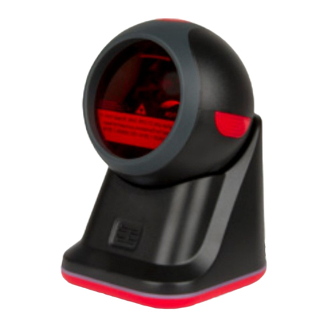
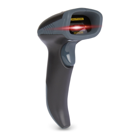
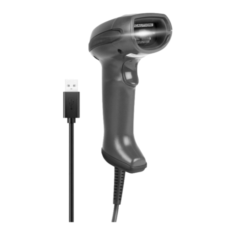
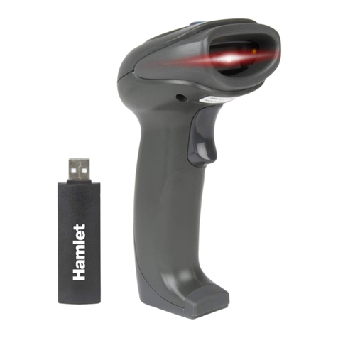
Hamlet HBCS2D100US User manual

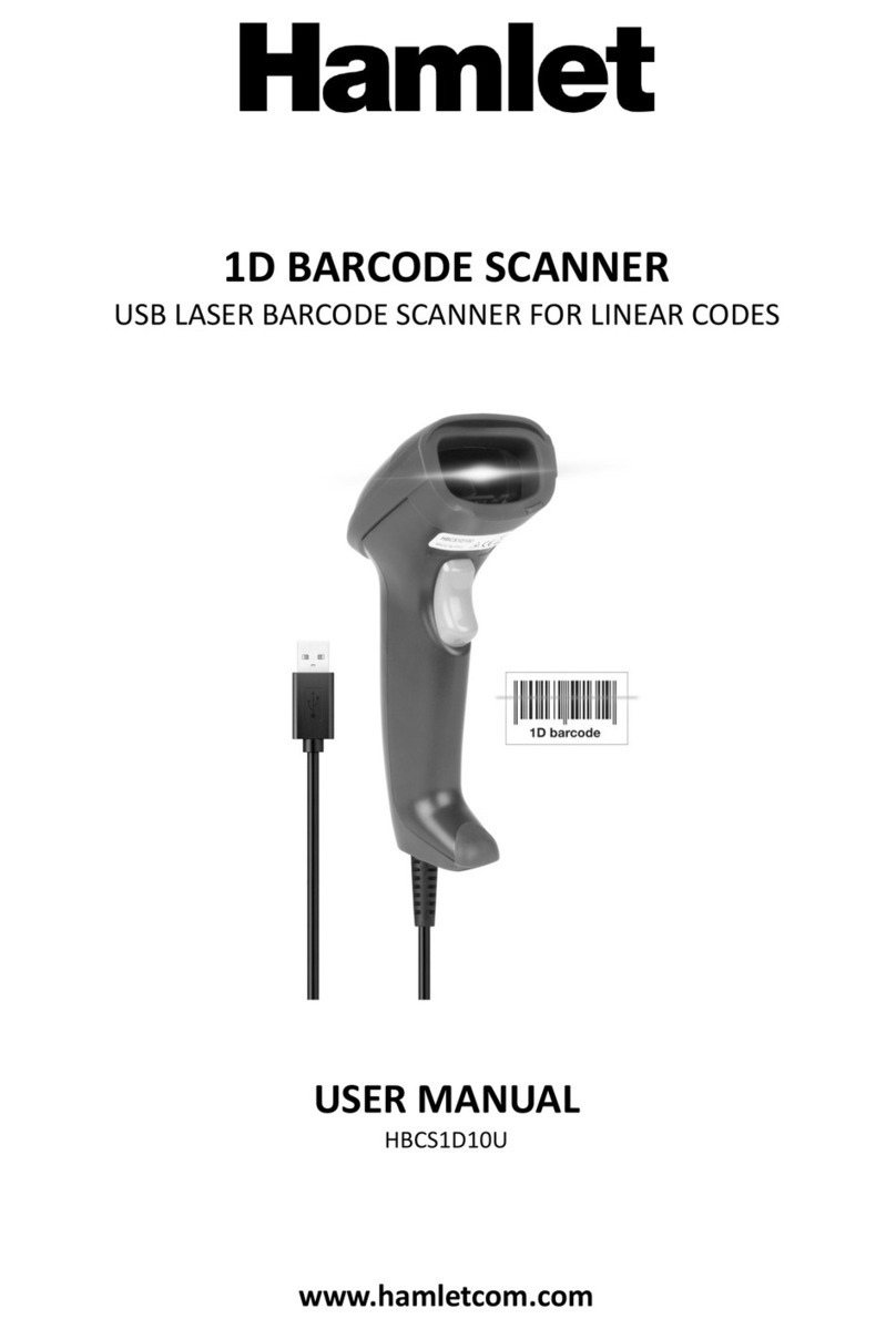
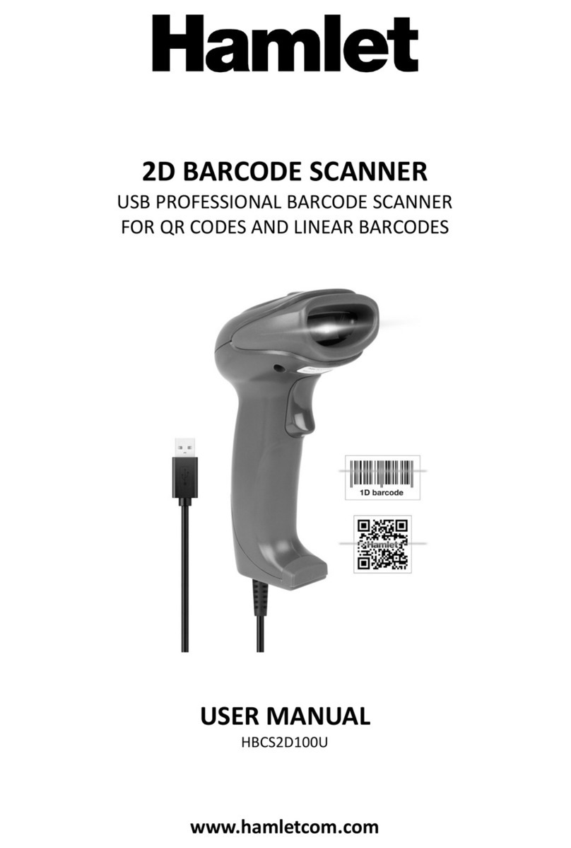
2D BARCODE SCANNER
USB PROFESSIONAL BARCODE SCANNER
FOR QR CODES AND LINEAR BARCODES
USER MANUAL
HBCS2D100U
www.hamletcom.com
Questo manuale d’istruzione è fornito da trovaprezzi.it. Scopri tutte le offerte per Hamlet
HBCS2D100US o cerca il tuo prodotto tra le migliori offerte di Palmari e Barcode Scanner

Dear Customer,
thanks for choosing an Hamlet product. Please carefully follow the instructions for its use and maintenance and,
once this item has run its life span, we kindly ask You to dispose of it in an environmentally friendly way, by putting
it in the separate bins for electrical/electronic waste, or to bring it back to your retailer who will collect it for free.
We inform You this product is manufactured with materials and components in compliance with RoHS Directive
2011/65/EU, WEEE Directive 2002/96/CE, 2003/108/CE Italian Legislative Decree 2005/151 and EMC Directive
2014/30/EU for the following standards:
EN 55032: 2015
EN 55024: 2010 + A1: 2015
The complete CE declaration of conformity of the product can be obtained by contacting Hamlet at
info@hamletcom.com.
Visit www.hamletcom.com for complete information on Hamlet products and to access downloads and technical
support.
Imported by: CARECA ITALIA SPA - Scandiano (RE) . Italy
All trademarks and company names mentioned in this manual are used for description purpose only and remain
property of their respective owners. The material in this document is for information only. Contents, specifications
and appearance of the product are indicative and may change without notice.
LED Devices
Hamlet products using led sources comply with IEC 60825-1, EN 60825-1: 2014. The led classification is marked on
one of the labels on the product. Class 1 Led devices are not considered to be hazardous when used for their
intended purpose.
The following statement is required to comply with US and international regulations:
Caution: Use of controls, adjustments or performance of procedures other than those specified herein may result
in hazardous led light exposure.
Class 2 Led scanners use a low power, visible light diode. As with any very bright light source, such as the sun, the
user should avoid staring directly into the light beam. Momentary exposure to a Class 2 Led is not known to be
harmful.
In accordance with Clause 5, IEC 60825 and EN 60825, the following information is provided to the user:
CLASS 1: CLASS 1 LED PRODUCT
CLASS 2: VISIBLE LED RADIATION - DO NOT STARE INTO BEAM - CLASS 2 LED PRODUCT

Table of Contents
Table of Contents ....................................................................................................................................................... 3
1 Start ................................................................................................................................................................... 5
1.1 Introduction ........................................................................................................................................... 5
1.2 About this Manual ................................................................................................................................. 5
1.3 Barcode reading operation .................................................................................................................... 5
1.4 Barcode Scanner Settings ...................................................................................................................... 5
1.4.1 Set Code Switch ......................................................................................................................... 5
1.4.2 Factory Default ........................................................................................................................... 6
1.4.3 User Default Settings ................................................................................................................. 6
2 Interface............................................................................................................................................................. 7
2.1 RS232 Communication Interface ........................................................................................................... 7
2.1.1 RS232 bit configuration ............................................................................................................. 8
2.1.2 Rs232 and full-code open quick configuration .......................................................................... 8
2.2 USB HID Interface .................................................................................................................................. 9
2.2.1 HID parameter configuration ..................................................................................................... 9
2.2.2 HID leading key output ............................................................................................................ 10
2.2.3 HID KBW and RS232 output ..................................................................................................... 11
2.3 USB-COM ............................................................................................................................................. 11
3 Scan mode (reading mode).............................................................................................................................. 12
3.1 Manual ................................................................................................................................................. 12
3.2 Successive scanning mode ................................................................................................................... 13
3.3 Autosensing Mode ............................................................................................................................... 15
3.4 Command Trigger mode ...................................................................................................................... 17
3.5 POS mode ............................................................................................................................................ 18
4 Reading area .................................................................................................................................................... 19
4.1 Full area ............................................................................................................................................... 19
4.2 Only the center area ............................................................................................................................ 19
5 Lighting and Aiming ......................................................................................................................................... 21
5.1 Lingting ................................................................................................................................................ 21
5.2 Aiming .................................................................................................................................................. 21
6 Prompt output ................................................................................................................................................. 22
6.1 All beeps .............................................................................................................................................. 22
6.2 Read the success tone ......................................................................................................................... 23
6.3 Data encoding format .......................................................................................................................... 23
6.4 National keyboard settings .................................................................................................................. 25
6.5 Virtual Keyboard Enable ...................................................................................................................... 25
6.6 Invoice mode is enabled ...................................................................................................................... 26
6.7 Image flip ............................................................................................................................................. 26
6.8 Black and white flip .............................................................................................................................. 27
6.9 Read the Version Information .............................................................................................................. 27
6.10 Reading unique ID of device ................................................................................................................ 27
7 Data editing ..................................................................................................................................................... 28
7.1 Prefix .................................................................................................................................................... 28
7.2 Suffix .................................................................................................................................................... 29
7.3 CODE ID ................................................................................................................................................ 30
7.4 terminator ............................................................................................................................................ 32
7.5 Data section interception .................................................................................................................... 32
7.6 RF information ..................................................................................................................................... 34
7.7 Output protocol ................................................................................................................................... 35
7.8 UPCA convert to to EAN 13 .................................................................................................................. 35
7.9 Product code verification output enable ............................................................................................. 35
8 Barcode type enable / disable configuration ................................................................................................... 36
8.1 All bar codes are solvable .................................................................................................................... 36
8.2 Readability ........................................................................................................................................... 36
8.3 EAN13 .................................................................................................................................................. 36

8.4 EAN8 .................................................................................................................................................... 37
8.5 UPCA .................................................................................................................................................... 38
8.6 UPCE0 .................................................................................................................................................. 38
8.7 UPCE1 .................................................................................................................................................. 39
8.8 Code128 ............................................................................................................................................... 39
8.9 Code39 ................................................................................................................................................. 40
8.10 Code93 ................................................................................................................................................. 41
8.11 CodeBar ............................................................................................................................................... 42
8.12 QR ........................................................................................................................................................ 43
8.13 Interleaved 2 of 5 ................................................................................................................................. 43
8.14 Industrial 25 ......................................................................................................................................... 44
8.15 Matrix 2 of 5 ........................................................................................................................................ 44
8.16 Code11 ................................................................................................................................................. 45
8.17 MSI ....................................................................................................................................................... 46
8.18 RSS ....................................................................................................................................................... 47
8.19 DM .................................................................................................. Errore. Il segnalibro non è definito.
8.20 PDF417 ................................................................................................................................................. 48
9 Appendix A: Default Settings Table .................................................................................................................. 49
10 Appendix B: Common Serial Instructions ........................................................................................................ 50
11 Appendix C: List of Code IDs ............................................................................................................................ 51
12 Appendix D: ASCII Code Table.......................................................................................................................... 52
13 Appendix E: Data Codes ................................................................................................................................... 56
14 Appendix F: Save or Cancel .............................................................................................................................. 58

1 Start
1.1 Introduction
HBCS2D100U barcode reader, the application of the country's leading intelligent image recognition
algorithm, and on this basis developed a set of advanced bar code reading algorithm, so as to realize the
reading of smaller size, higher version of the bar code function
1.2 About this Manual
This manual mainly provides various function setting commands of HBCS2D100U reader. By familiarizing
yourself with the introduction of various function commands in this manual, you can change the function
parameters of HBCS2D100U, such as communication interface parameters, reading mode, prompt mode and
so on.
HBCS2D100U products have been shipped from the factory has been configured to fit most commonly
used functions of the parameters, in most cases the user can make adjustments without adjustment can be
used in the appendix of this manual, lists the default HBCS2D100U features and parameters for reference.
1.3 Barcode reading operation
Thanks to the leading image recognition algorithm in the country and the barcode decoding algorithm
developed on this basis, it is very easy and accurate to read barcode symbologies. Even if the bar code symbol
at any rotation angle, will not affect the reading. In reading, the HBCS2D100U aimed at reading the bar code
symbol can be.
1.4 Barcode Scanner Settings
1.4.1 Set Code Switch
By turning on the setting code function, the parameter setting of the reader can be performed by scanning
the setting code.
* On
Off
Output setting code content
* Not
Yes

1.4.2 Factory Default
By scanning the "Factory Default " barcode, all the reader parameters can be restored to the factory
configuration.
Factory Default
1.4.3 User Default Settings
In addition to the factory settings, the user can also save their frequently used configuration as the default
settings of the user, and save the current configuration information of the device as the default setting information
of the user by scanning "Save current setting as user default setting". If the reader The user has the default setting
information, the new configuration information after the operation will replace the original user default setting
information.
By scanning "Restore user default settings" can be changed to the reader user default setting information.
Save current settings as user
defaults
Restore user default settings

2 Interface
HBCS2D100U reader provides TTL-232 serial communication interface to communicate with the host.
Through the communication interface, you can receive the read data, send commands to the reader to control,
and change the reader's function parameters.
2.1 RS232 Communication Interface
Serial communication interface is a common way to connect the reader with the host device (such as PC,
POS, etc.). When the reader and the host using a serial cable connection, the system uses serial
communication mode by default. The use of serial communication interface, the reader and the host device
must be in the communication parameters on the configuration to match, in order to ensure smooth
communication and content is correct.
Serial output
The reader's serial communication interface uses the TTL-level signal (TTL-232), which adapts to most
system architectures. If the system requires the use of RS-232 form of the structure, the need to increase the
external conversion circuit.
The default serial communication parameters of the reader are shown in Table 2-1. Among them, the baud
rate of the reader can be modified through the serial port command, but the remaining parameters can not be
modified.
Form 2-1 Default serial communication parameters
Parameter
Default
Serial communication type
Standard TTL-232
Baud rate
9600
Check
Not
Data bit
8
Stop bit
1
Hardware flow control
Not
Baud rate setting
1200bps
4800bps
* 9600bps

14400bps
19200bps
38400bps
57600bps
115200bps
2.1.1 RS232 bit configuration
Customers can modify the serial parity by scanning the following configuration code.
* NONE
ODD
EVEN
2.1.2 RS232 and full-code open quick configuration
In order to help customers quickly configure the serial port and full-code open mode during secondary
development, quick configuration function can be realized by scanning the following configuration codes.
Serial & Full open

2.2 USB HID Interface
When the reader module is connected to the host using a USB cable, the reader module can be configured
as a HID device by scanning the following setup code.
USB HID device
When the device is used as a HID device, it can be 2 different devices. Configure the following settings.
2.2.1 HID parameter configuration
You can also modify the PC's access cycle to the HID device by scanning the following setup code.
* 1ms
3ms
5ms
10ms
You can also modify the interval between valid message and release message of the device by scanning
the following setting codes.
* 0ms
1ms
5ms

10ms
15ms
You can also modify the interval between the device to release the packet and the next valid packet by
scanning the following setting code.
0ms
* 1ms
5ms
10ms
15ms
You can also modify the status of the CapsLock on output by scanning the following setup code.
* Off
On
2.2.2 HID leading key output
Users can scan the following configuration code to output a preamble message before outputting each
piece of data from HID, which is convenient for customer software development and positioning.
The key value is ctrl+shift+r
HID disable
HID enable

2.2.3 HID KBW and RS232 output
The user can scan the following configuration code to enable data output through the serial port while
HIDKBW is output.
Disable
Enable
2.3 USB-COM
When the HBCS2D100U is connected with the host using the USB cable, the module can be configured
as a virtual serial port output mode by scanning the USB virtual serial port setting code.
USB-COM

3 Scan mode (reading mode)
3.1 Manual
Manual reading mode is the default reading mode. In this mode, the HBCS2D100U starts reading the code
after pressing the trigger key, and stops the reading after the reading code successfully outputs the message
or releases the trigger key.
* Manual
In this mode, HBCS2D100U default idle for a certain period of time, automatically enter the deep sleep
mode, can be set by the following setup code.
Sleep time On
* Sleep time OFF
After entering sleep mode, wake up by pressing the key, the device will reboot after exiting sleep mode.
In addition, when deep sleep is not enabled, you can also set the light sleep idle time by scanning the
following setting codes.
0ms
* 500ms
3000ms
5000ms

3.2 Successive scanning mode
After setting, without trigger, HBCS2D100U reader immediately start reading, reading code successfully
output information or single reading time after the end, HBCS2D100U wait for a period of time (can be set) will
automatically start the next reading. If the following conditions do not occur, HBCS2D100U reader will work in
the above cycle: During reading the user can also click the trigger button to manually pause the reading. Click
the trigger button HBCS2D100U will continue to cycle reading.
Successive Scanning mode
Single reading time
In continuous reading mode, this parameter refers to the reading before the success of HBCS2D100U
reader to allow continued recognition of the maximum acquisition time. After a successful reading or a single
reading time-out, the HBCS2D100U reader enters the interval of not acquiring readings. Single reading time
length setting range of 0.1 ~ 25.5 seconds, step 0.1 seconds; when set to 0, said the reading time unlimited.
The default duration is 5.0 seconds.
1000ms
3000ms
* 5000ms
Unlimited time
Reading interval length
This parameter refers to the interval between two adjacent readings, that is, after finishing the last reading
of the reader (no matter the reading is successful or not), the reading will not be carried out within the set
interval, until the interval ends After reading the next code. The reading interval setting range is from 0 to 25.5
seconds in 0.1 second steps. The default interval is 1.0 second.
No gap
500ms
* 1000ms

1500ms
2000ms
The same bar code reading delay
in order to prevent the same code from being read multiple times in succession, the reader can be asked
to read the same code if it can not read the same code continuously for a period of time in this mode.
The same barcode reading delay means that the reader will read the same barcode and compare with the
last reading time. When the interval time is longer than the reading delay time, the same barcode is allowed to
be read out, otherwise the output is not allowed.
The same bar code reading
delay
* The same bar code reading
is not extended
The same barcode reading delay time
After enabling the same barcode reading delay, the same barcode reading delay time can be set through the
following setting codes
Unlimited delay
500ms
1000ms
3000ms
5000ms

3.3 Autosensing Mode
After setting, without trigger, the reader immediately began to monitor the brightness of the surrounding
environment, when the scene changes, the reader waits for the set of image stabilization time after the end of
reading. After reading the successful output of information or single reading time-out after the reader to be
some time interval (can be set) to re-enter the monitoring state. If the following conditions do not occur, the
reader will cycle in the above way: In a single reading time bar code is not scanned, the reader will automatically
pause reading and into the monitoring state. In the inductive reading mode, the reader can also start reading
the code after pressing the trigger key, and continue to monitor the brightness of the surrounding environment
when the reading code successfully outputs the message or release the trigger key.
Autosensing mode
Single reading time
In inductive reading mode, this parameter refers to the maximum length of time that the reader will be
allowed to continue acquisition recognition before the reading is successful. After a successful reading or a
single reading timeout, the reader will enter the interval of not acquiring readings.
Single reading time length setting range of 0.1 ~ 25.5 seconds, step 0.1 seconds. When set to 0, the
reading time is infinite. The default duration is 5.0 seconds.
1000ms
3000ms
*5000ms
Unlimited time
Reading interval length
After reading the successful output of information or single reading time-out, the reader needs to be some
time (can be set) to re-enter the monitoring state. The reading interval setting range is from 0 to 25.5 seconds
in 0.1 second steps. The default interval is 1.0 second.
No interval
500ms
* 1000ms

1500ms
2000ms
Stable time
Stabilization time length refers to the sensor reading mode, detect the scene changes in the reader before
reading the picture need to wait for the image stabilization time. Stabilization duration is set from 0 to 25.5
seconds in 0.1 second steps. The default image duration is 0.4 seconds.
100ms
*400ms
1000ms
2000ms
Sensitivity
Sensitivity refers to the degree of change of the scene detected in the sense reading mode. When the
reader to determine the degree of change in the scene to meet the requirements, will switch from monitoring
status to read status.
* Normal sensitivity
Low Sensitivity
High sensitivity
Very high sensitivity
The same bar code reading delay
It is not avoided that the same code is read consecutively multiple times, and the reader may be required
to read the same code if it can not read the same code continuously for a period of time in this mode. Set code
and continuous mode the same.

3.4 Command Trigger mode
In this mode, the reader starts to read the code when it receives the scan command sent by the host (ie
bit0 of flag 0x0002 is written to "1"), and stops reading after the reading succeeds in outputting the message or
the reading time of single reading.
Command trigger mode
Note: In the command triggering mode, the serial port triggering the scan command is: 7E 00 08 01 00 02
01 AB CD; Upon receiving the trigger command, the reader will output seven bytes of response message and
start the scan synchronously Information content: 02 00 00 01 00 33 31).
Single reading time
In command triggered reading mode, this parameter refers to the maximum length of time that the reader
is allowed to continue acquisition recognition before the reading is successful. Single reading time length setting
range of 0.1 ~ 25.5 seconds, step 0.1 seconds. When set to 0, the reading time is infinite. The default duration
is 5.0 seconds.
1000ms
3000ms
* 5000ms
Infinitely long

3.5 POS mode
The user can quickly configure the module to work in the POS mode by scanning the following setting
code, including the following main features:
1: Read mode is command trigger mode;
2: The communication interface is RS232;
3: Turn off the start tone;
4: Close the end terminator;
POS Mode

4 Reading area
For different applications, users need to identify the area there will be some differences, by scanning the
following setting code can be set.
4.1 Full area
When the reading area is full area, the reader will scan the barcode with the center as the priority, and the
barcode may be anywhere on the screen.
* Full area
4.2 Only the center area
When the reading area is the center area, the center position of the barcode must be within the set center
area, and the bar codes that are not in the area are not recognized and output.
Only the center area
Set the center area size
The center area is an area centered on the whole image center. The size of the area is set in proportion to
the width or height of the entire image, ranging from 1 to 100. If the setting value is 20, that is, Located in a
center area of 20% of the width of a 20% height area.

Modify the center area size
Commonly used center area size can be set by scanning the following setting code:
Center area -20%
Center area -40%
Center area -60%
When the size of the commonly used central area does not meet the needs, the user can also customize
the configuration by scanning the "edit center area size" setting code.
Modify the center area size
Example:modify the 50% center area size
1. Check the character table to get "50" four characters hexadecimal value: "32"
2. Check whether the setting code is on. If it is not on, please scan the setting code "on" (see section 1.5.2)
3. Scan "Modify center area size" setting code
4. Scan the data setting code "3", "2" (see appendix E)
5. Scan "save" setting code (see Appendix F)
This manual suits for next models
1
Table of contents
Other Hamlet Barcode Reader manuals

Hamlet
Hamlet HBCS-2D110W User manual

Hamlet
Hamlet HBCS2D100U User manual

Hamlet
Hamlet HBCS2D100W User manual

Hamlet
Hamlet HBCS1D360 User manual

Hamlet
Hamlet HBCS1D10US User manual

Hamlet
Hamlet HBCS2D100W User manual

Hamlet
Hamlet HBCS2D300U User manual

Hamlet
Hamlet HBCS1D10W User manual

Hamlet
Hamlet HBCS1D10U User manual