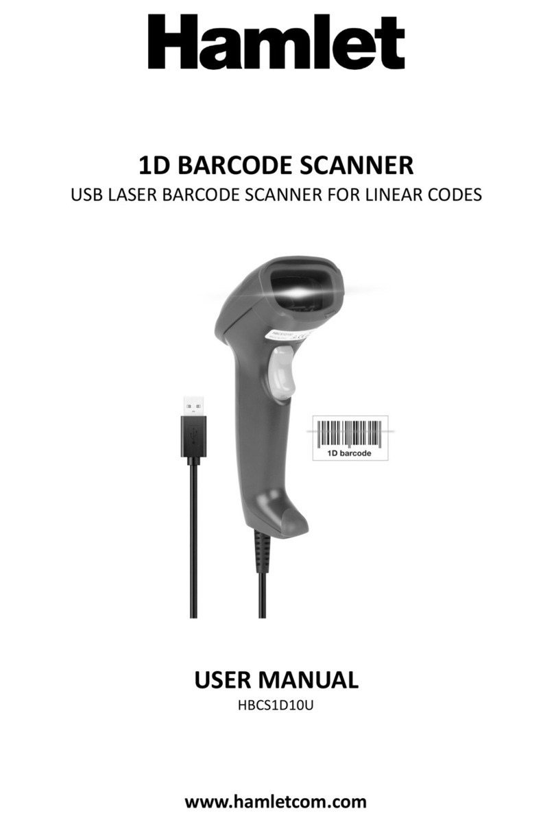
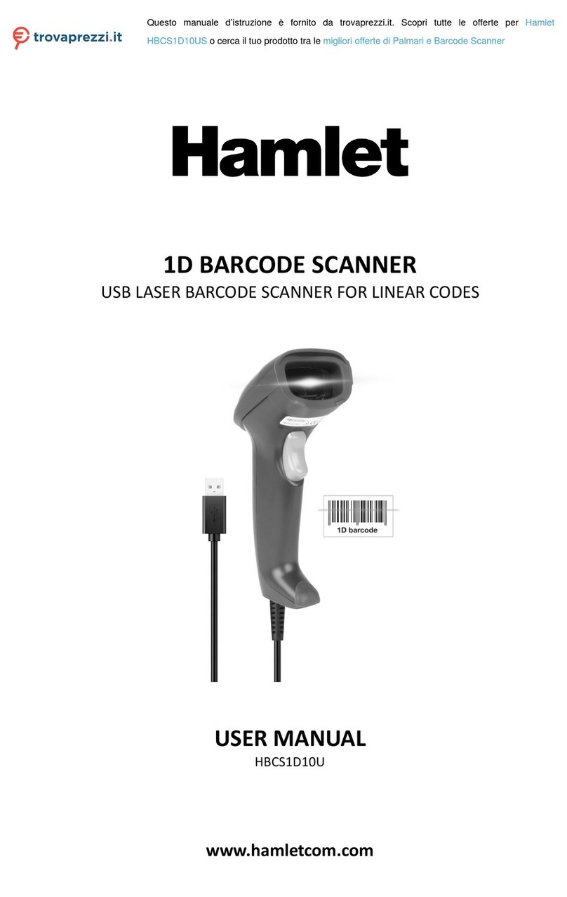
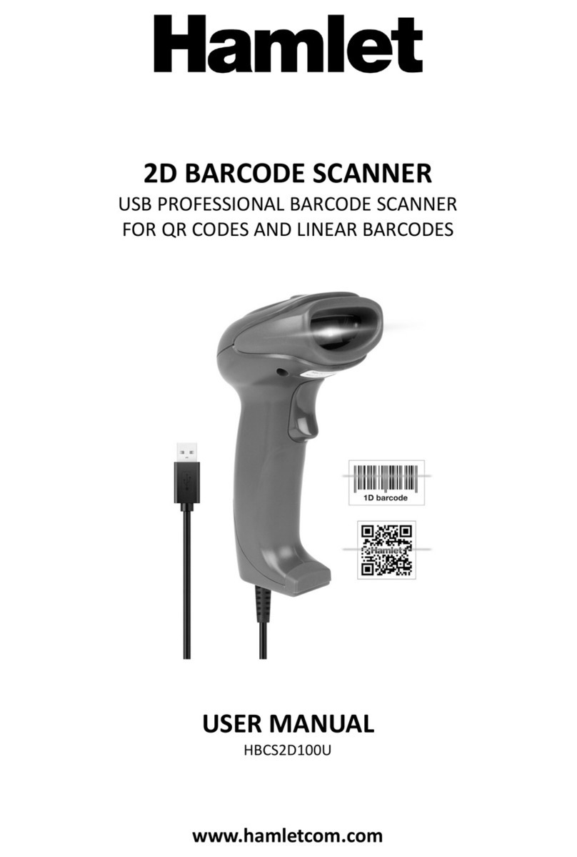
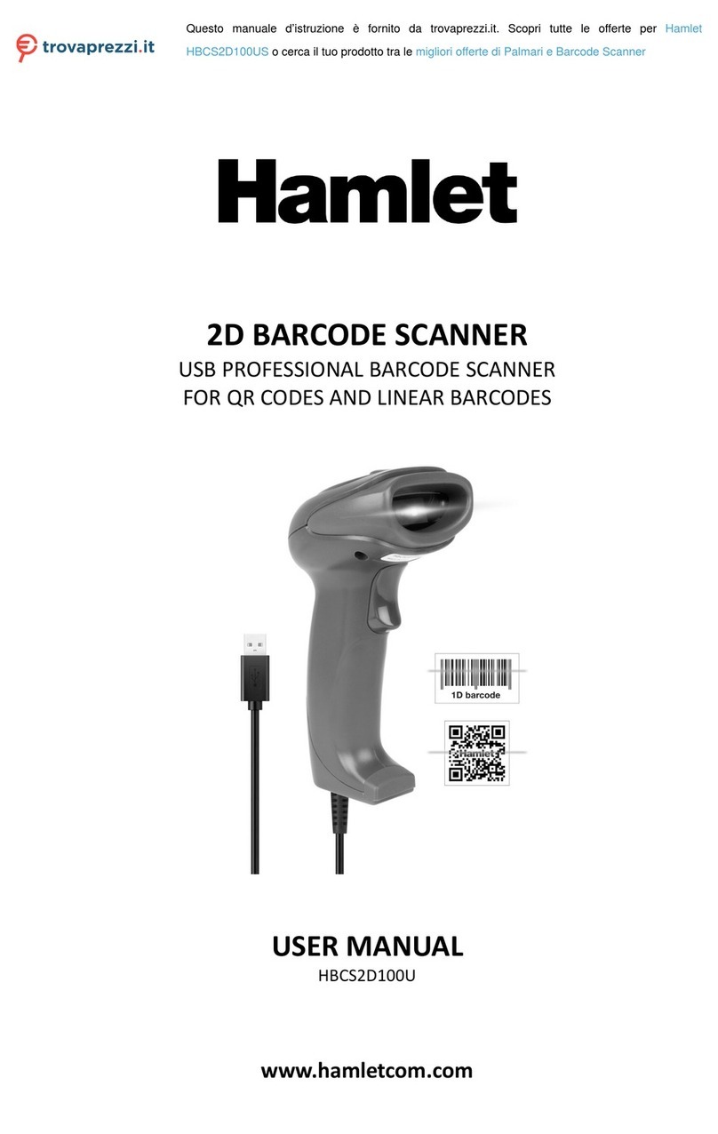
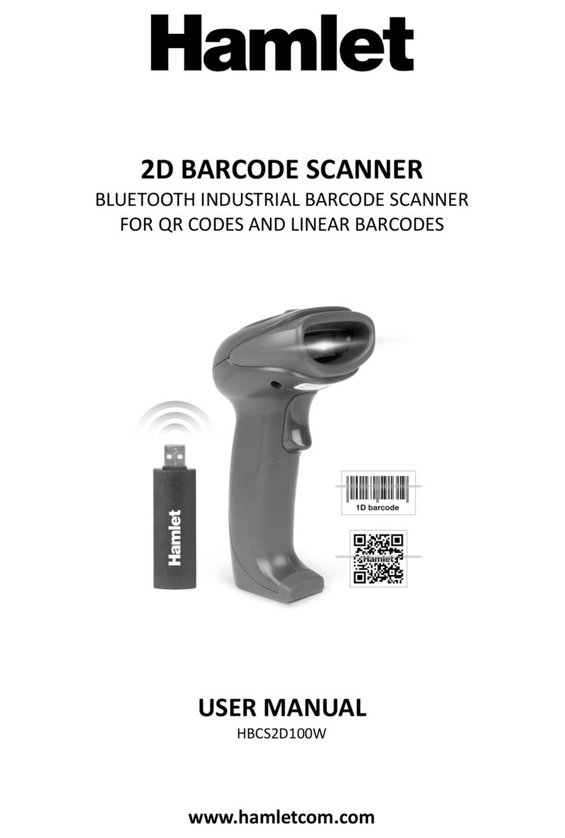
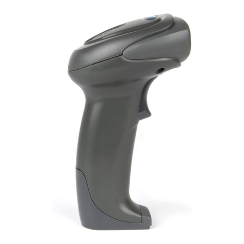
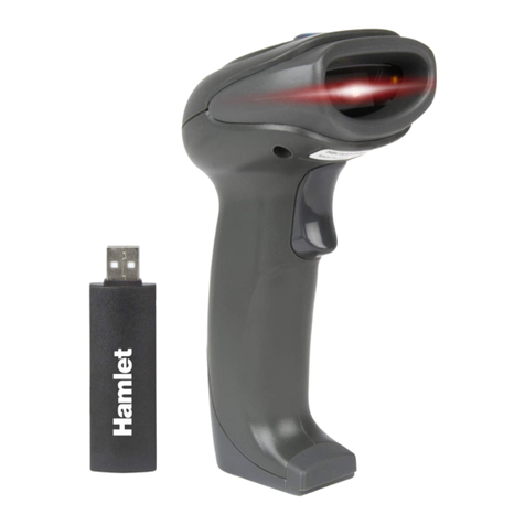
Hamlet HBCS-2D110W User manual

2D BARCODE SCANNER
WIRELESS 2.4GHz + BLUETOOTH SCANNER
FOR QR CODES AND LINEAR BARCODES
USER MANUAL
HBCS-2D110W
www.hamletcom.com

2
Dear Customer,
thanks for choosing an Hamlet product. Please carefully follow the instructions for its use and
maintenance and, once this item has run its life span, we kindly ask You to dispose of it in an
environmentally friendly way, by putting it in the separate bins for electrical/electronic waste, or to
bring it back to your retailer who will collect it for free.
We inform You this product is manufactured with materials and components in compliance with RoHS
Directive 2011/65/EU & 2015/863/EU, WEEE Directive 2002/96/CE, 2003/108/CE Italian Legislative
Decree 2005/151 and RED Directive 2014/53/EU for the following standards:
EN 62479: 2010, EN 62368-1: 2014 / A11: 2017, ETSI EN 301 489-1 V2.2.3 (2019-11),
ETSI EN 301 489-17 V3.2.4 (2020-09), ETSI EN 300 328 V2.2.2 (2019-07).
CE Mark Warning
This is a Class B product. In a domestic environment, this product may cause radio interference, in which
case the user may be required to take adequate measures.
The complete CE declaration of conformity of the product can be obtained by contacting Hamlet at
info@hamletcom.com.
Visit www.hamletcom.com for complete information on Hamlet products and to access downloads and
technical support.
Imported by: CARECA ITALIA SPA - Scandiano (RE) . Italy
All trademarks and company names mentioned in this manual are used for description purpose only and
remain property of their respective owners. The material in this document is for information only. Contents,
specifications and appearance of the product are indicative and may change without notice.
LED Devices
Hamlet products using led sources comply with IEC 60825-1, EN 60825-1: 2014. The led classification is
marked on one of the labels on the product. Class 1 Led devices are not considered to be hazardous when
used for their intended purpose.
The following statement is required to comply with US and international regulations:
Caution: Use of controls, adjustments or performance of procedures other than those specified herein may
result in hazardous led light exposure.
Class 2 Led scanners use a low power, visible light diode. As with any very bright light source, such as the
sun, the user should avoid staring directly into the light beam. Momentary exposure to a Class 2 Led is not
known to be harmful.
In accordance with Clause 5, IEC 60825 and EN 60825, the following information is provided to the user:
CLASS 1: CLASS 1 LED PRODUCT
CLASS 2: VISIBLE LED RADIATION - DO NOT STARE INTO BEAM - CLASS 2 LED PRODUCT

3
Table of Contents
1. Operation Settings .............................................................................................................................. 6
1.1 Use of Programming Barcode .................................................................................................. 6
1.2 Restore Factory Defaults .......................................................................................................... 7
1.3 User Default Settings................................................................................................................ 7
2. Communication Interface................................................................................................................... 8
2.1 Selection of Communication Mode.......................................................................................... 8
2.1.1 Output Mode of Communication Port........................................................................... 8
2.2 Serial Communication Interface............................................................................................... 9
2.2.1 Baud Rate ...................................................................................................................... 9
2.2.2 Parity Methods............................................................................................................. 10
2.3 Configuration of USB-HID Interface Related Parameter....................................................... 11
2.3.1 Selection of HID Devices............................................................................................ 11
2.3.2 Access Cycle of PC to HID Device............................................................................. 11
2.3.3 Timeout Before HID Release ...................................................................................... 12
2.3.4 Timeout After HID Release......................................................................................... 12
2.3.5 CapsLock Status Settings ............................................................................................ 13
2.3.6 Leading Key Output .................................................................................................... 13
3. Scanning Mode................................................................................................................................. 14
3.1 Manual Mode.......................................................................................................................... 14
3.1.1 Trigger Conditions....................................................................................................... 14
3.1.2 Decode Session Timeout ............................................................................................. 14
3.2 Command Trigger Mode ........................................................................................................ 15
3.2.1 Decode Session Timeout ............................................................................................. 16
3.3 Continuous Mode ................................................................................................................... 16
3.3.1 Timeout Between Decodes.......................................................................................... 16
3.3.2 Timeout between Decodes (Same Barcode)................................................................ 17
3.3.3 Decode Session Timeout ............................................................................................. 18
3.3.4 Continuous mode key pause switch............................................................................. 18
3.4 Sense Mode ............................................................................................................................ 18
3.4.1 Decode Session Timeout ............................................................................................. 19
3.4.2 Timeout between Decodes........................................................................................... 19
3.4.3 Timeout between Decodes (Same Barcode)................................................................ 19
3.4.4 Sensitivity.................................................................................................................... 19
3.4.5 Image Stabilization Timeout ....................................................................................... 20
4. Filling Light...................................................................................................................................... 21
4.1 Fill Light................................................................................................................................. 21
4.2 Positioning.............................................................................................................................. 21
5. Prompt Output.................................................................................................................................. 23
5.1 Buzzer Master Switch............................................................................................................. 23
5.2 Buzzer Settings....................................................................................................................... 23
5.2.1 Passive Buzzer............................................................................................................. 23
5.2.2 Active Buzze ............................................................................................................... 23

4
5.3 Good Read Beep for Programming Barcode.......................................................................... 24
5.5 Good Read LED/Beep............................................................................................................ 25
5.6 Data Output Encoding Format................................................................................................ 25
5.7 Different Country Keyboard Settings..................................................................................... 26
5.8 Virtual keyboard enable.......................................................................................................... 27
5.9 Chinese output shielding ........................................................................................................ 30
5.10 Analog keypad...................................................................................................................... 31
5.10.1 Output of numeric function of keypad....................................................................... 31
5.10.2 Output of keypad operator function........................................................................... 31
5.11 Image Mirroring Mode ......................................................................................................... 32
5.12 Reverse Scanning Module.................................................................................................... 32
5.13 Invoicing mode..................................................................................................................... 32
5.14 Read Device Version Information........................................................................................ 33
5.15 Write/Read Device ID .......................................................................................................... 33
5.16 Read Chip SN....................................................................................................................... 34
6. Prefix & Suffix ................................................................................................................................. 36
6.1 Prefix ...................................................................................................................................... 36
6.2 Suffix...................................................................................................................................... 37
6.3 Code ID .................................................................................................................................. 37
6.3.1 Custom Code ID.......................................................................................................... 37
6.3.2 Modify Code ID .......................................................................................................... 38
6.4 Tail.......................................................................................................................................... 40
6.5 Data Character........................................................................................................................ 40
6.5.1 Date Character Interception......................................................................................... 40
6.5.2 Modify the Length for Data......................................................................................... 41
6.6 RF Information ....................................................................................................................... 41
6.7 Output Protocol ...................................................................................................................... 42
6.8 GS Character Replacement..................................................................................................... 42
6.9 Web address code recognition................................................................................................ 43
7. Quick Operation ............................................................................................................................... 44
7.1 Fast POS Mode....................................................................................................................... 44
7.2 Serial Port & Full Codes On Mode ........................................................................................ 44
8. Symbologies ..................................................................................................................................... 45
8.1 Global Shortcuts..................................................................................................................... 45
8.1.1 Global Operations........................................................................................................ 45
8.1.2 Product Barcode Check Digit Output Enable.............................................................. 45
8.1.3 Enhancement of literacy .............................................................................................. 45
8.2 1D Symbologies ..................................................................................................................... 46
8.2.1 EAN 13........................................................................................................................ 46
8.2.2 EAN 8.......................................................................................................................... 47
8.2.3 UPC-A......................................................................................................................... 48
8.2.4 UPC-E0 ....................................................................................................................... 50
8.2.5 UPC-E1 ....................................................................................................................... 51
8.2.6 Code128....................................................................................................................... 52
5
8.2.7 Code39......................................................................................................................... 53
8.2.8 Code93......................................................................................................................... 55
8.2.9 CodaBar....................................................................................................................... 56
8.2.10 Interleaved 2 of 5....................................................................................................... 57
8.2.11 Industrial 25............................................................................................................... 58
8.2.12 Matrix 2 of 5.............................................................................................................. 60
8.2.13 Code11....................................................................................................................... 61
8.2.14 MSI Plessey............................................................................................................... 62
8.2.15 RSS-14....................................................................................................................... 63
8.2.16 RSS-Limited.............................................................................................................. 63
8.2.17 RSS-Expanded........................................................................................................... 64
8.3 Operation of 2D Symbologies ................................................................................................ 65
8.3.1 QR Code ...................................................................................................................... 65
8.3.2 Data Matrix (DM)........................................................................................................ 66
8.3.3 PDF417........................................................................................................................ 67
8.3.4 Mico QR ...................................................................................................................... 67
8.3.5 Chinese Sensible(HanXin) Code ................................................................................. 67
9. Save and Cancel ............................................................................................................................... 68
9.1 Save ........................................................................................................................................ 68
9.2 Cancel..................................................................................................................................... 68
10. Batch Setting .................................................................................................................................. 69
Appendix .............................................................................................................................................. 70
Appendix A: Digit Barcodes ........................................................................................................ 70
0 ~9.................................................................................................................................. 70
A ~F................................................................................................................................... 71
Appendix B: Example of Parameter Settings............................................................................... 72
Appendix C: Default Settings Table............................................................................................. 74
Appendix D: Common Serial Commands .................................................................................... 81
Appendix E: Code ID List............................................................................................................ 82
Appendix F: ASCII Table ............................................................................................................ 83
Appendix G Batch Setting Code Content Parameter List............................................................. 88

6
1. Operation Settings
The factory default settings of the WSM-QL1601 are designed to meet the direct use of users in most
cases. You can also set the parameters by setting the code according to the actual use.
1.1 Use of Programming Barcode
Scan "enter programming barcode" to configure the module function (set code function). After booting
the function, the parameter can be modified by reading one or more programming barcodes. After
recognizing "exit programming barcode", the scanning module will exit the setting mode.
**Enter Setup Exit Setup
Enable and disable the output of set code content.
Transmit Programming Barcode Data **Do Not Transmit Programming Barcode Data
Note: The optionmarked with (**) in the programming barcode indicates the default function or
paramet.

7
1.2 Restore Factory Defaults
After reading this programming barcode, the current parameter setting will be lost and the factory
default value will be restored. Factory default parameters and functions can be found in Appendix C.
Restore Factory Defaults
Note: Please use the "Restore Factory Defaults" function with caution.
1.3 User Default Settings
In addition to the factory reset, users can save frequently used settings as user defaults. By reading "Save
as Custom Defaults", you can save the current device configuration as user default information so that you can
make quick settings when needed.
The default settings saved by the user can be restored by reading "Restore Custom Defaults".
Save as Custom Defaults Restore Custom Defaults

8
2. Communication Interface
The WSM-QL1601 scanning module provides a TTL-232 serial communication interface and a USB
interface (optional function) for communication with the host. The reading data can be received through the
communication interface.
2.1 Selection of Communication Mode
The USB-HID mode is default for communication. Users can switch between communication port
output modes by reading code settings (TTL-232 Serial Port Mode / Virtual Serial Port / USB-HID Mode).
When USB output and serial port output are needed at the same time, you can select the HID & TTL
Simultaneous Output Mode by reading the programming barcode. When users switch communication mode,
it is necessary to wait for the device initialization to complete before performing related operations.
Note1: When the module is set as USB Virtual Serial Port and communicates with the host through this
port, the corresponding driver needs to be installed in the host.
Note1::The USB-HID uses 2 numbers to identify the device and find the correct device.
VID&PID information is shown in the following table:
Interface Type
VID(HEX)
PID(HEX)
USB Virtual Serial Port
0x152A
0x880F
HID-KBW
0x1FC9
0x5AA7
HID-POS
0x1FCA
0x5AA8
2.1.1 Output Mode of Communication Port
Scan the following programming barcode to set the communication output mode.
TTL-232 Serial Port Mode **USB-HID Mode

9
USB Virtual Serial Port Mode HID & TTL Simultaneous Mode
2.2 Serial Communication Interface
The serial communication interface is a common way to connect the scanning module to the host
device. When the serial communication interface in running, the communication module must be
completely matched with the host device to ensure smooth communication and correct content.
The serial communication interface provided by the scanning module are TTL -level signals. TTL-232
can be used for most application architectures.For those requiring RS-232, an external conversion circuit is
needed.
The default serial communication parameters of the scanning module are as follows. When they are
inconsistent with the host device, they can be modified by reading the programming barcode.
Default communication parameters of TTL-232:
Parameter
Default
Serial Communication Type
TTL-232
Baud Rate
9600
Parity Type
None
Data Bits
8
Stop Bits
1
2.2.1 Baud Rate
The Baud Rate is in bps: bits per second. You can scan the following programming barcodes to select
configuration parameters.

10
1200bps 4800bps
**9600bps 14400bps
19200bps 38400bps
57600bps 115200bps
2.2.2 Parity Methods
There are 3 alternative parity methods, as follows:
**None

11
ODD Parity Even Parity
2.3 Configuration of USB-HID Interface Related Parameter
2.3.1 Selection of HID Devices
When the product is set as HID devices,it could be two different devices。Users can scan the
following programming barcode to set.
**HID-KBW HID-POS
HID-POS acquire scan data
After scanning and decoding a barcode, the device would send the following input message.
Data reception
Bit
Byte
7
6
5
4
3
2
1
0
0
Message ID=0x02
1
Bar Code Data Length
2
Fixed Value 0x5d
3
Fixed Value 0x51
4
Fixed Value 0x31
5-60
Barcode Data
61
Barcode Data
62
Fixed Value 0x51
63
0x01 (followed by packets)/0x0 (followed by no packets)
2.3.2 Access Cycle of PC to HID Device
You can modify the access period of PC to HID device by reading the following programming
barcode. The period ranges from 1ms to 64ms.

12
**1ms 3ms
5ms 10ms
2.3.3 Timeout Before HID Release
After reading the following programming barcode, you can modify the timeout before the HID is
released (that is, the timeout from valid message to release message). The timeout is from 1ms to 63ms.
**1ms 2ms
5ms 10ms
2.3.4 Timeout After HID Release
After reading the following programming barcode, you can modify the timeout after the HID is
released (that is, the timeout from the release of the message to the next valid message). The timeout is
from 1ms to 63ms.
**1ms 2ms

13
5ms 10ms
2.3.5 CapsLock Status Settings
** CapsLock-Off CapsLock-On
2.3.6 Leading Key Output
Users can scan the following programming barcode to enable HID to output a preamble message before
outputting each piece of data, which is convenient for client as to software development and positioning.
The key value is Ctrl+Shift+r.
** Disable HID Leading Key Output Enable HID Leading Key Output

14
3. Scanning Mode
3.1 Manual Mode
Manual mode is a default scanning module. In manual mode, press the trigger button, the scanning
module starts shooting and reading. In the limited duration of "Decode Session Timeout". After successful
reading, the scanning module will output the scanned content through the communication interface and
stop reading, if you need to one more reading, you need to re-trigger the button. If the reading exceeds the
length of a single reading in time duration, the shooting and reading will be stopped.
Manual Mode
3.1.1 Trigger Conditions
The trigger condition can be selected in the manual mode. The trigger condition defaults to level
triggering and level triggering.
FEdge triggering refers to the detection of the level pulse of the trigger signal, that is, start reading,
and the reading is ended when the reading is successful or the decode session timeout condition is reached.
FThe Level Trigger condition refers to the level at which the trigger signal needs to be held during
the start of reading to the end of reading. When the trigger level is cancelled, the reading is successful, or
the reading is longer than the single reading duration, the reading is ended.
Edge Trigger **Level Trigger
3.1.2 Decode Session Timeout
Decode Session Timeout is the time allowed to conduct the longest reading after the reading is triggered.
When the time is exceeded, it will exit the reading state. The range is from 100ms to 25500ms. Scan the
following programming barcode to set the Decode Session Timeout.

15
1000ms 3000ms
**5000ms 10000ms
Infinite
3.2 Command Trigger Mode
In the command trigger mode, the scanning module starts shooting and reading after receiving the
trigger signal command sent by the host (that is, the bit 0 of the flag bit 0x0002 is written to "1"); within
the limited time range of "decode session timeout" If the reading is successful, the scanning module will
output the scan content through the communication interface and stop reading. If a new reading is to be
booted, the trigger command needs to be resent. If the reading exceeds the length of a single reading in
time duration, the reading will be stopped.
Command Trigger Mode
Note: In the command trigger mode, the serial command of the trigger signal is: 7E 00 08 01 00 02 01
AB CD; After receiving the scan commands, the serial port returns the write success command: 02 00 00
01 00 33 31, the scanning module is booted.
Trigger command answer switch
Read the following setting codes to allow and prohibit the trigger command response.

16
Trigger command response disable ** Trigger command response allowed
3.2.1 Decode Session Timeout
For the single reading duration setting, please refer to 3.1.2 Decode Session Timeout Code to set.
3.3 Continuous Mode
Continuous Mode is a way for the scanning module to continuously capture, scan and output
information.
In this mode, it is defaulted to go into the 1000ms reading timeout after successful reading.
In Continuous Mode, you can use the trigger level control to pause continuous reading or continue
reading continuously. In continuous reading, it is necessary to maintain the trigger level of 50ms or more
and then cancel it, so that the reading will be suspended. When the reading state is suspended, the trigger
level of 50ms or more is also maintained and then canceled, and the reading is continued.
Continuous Mode
3.3.1 Timeout Between Decodes
It refers to the timeout between the next reading and the current successful reading. No acquisition is
performed during this timeout. Scan the following programming barcode to set timeout between decodes.
The setting is from 0ms to 25500ms, and the default duration is 1000ms.
No Timeout

17
500ms **1000ms
3000ms 5000ms
3.3.2 Timeout between Decodes (Same Barcode)
In order to avoid the same barcode being continuously scanned for multiple times in continuous mode,
Timeout between Decodes (Same Barcode) is required for scanning module in this mode before enabling the
same barcode. Timeout between Decodes (Same Barcode) means that the same barcode will not be read if it
has been scanned within the set timeout. It can only be read and output beyong the timeout. By default,
Timeout between Decodes (Same Barcode) is turned off.
ON ** OFF
Scan the following programming barcode to set Timeout between Decodes (Same Barcode). Setting
range: 0ms~12700ms.
FNote: The delay time setting can be set only after the "Timeout between Decodes (Same Barcode)"
is turned on.

18
Infinite Delay 500ms
1000ms 3000ms 5000ms
3.3.3 Decode Session Timeout
For the decode session timeout, please refer to the programming barcode of Section 3.1.2 Decode
Session Timeout.
3.3.4 Continuous mode key pause switch
When "Continuous Mode Key Pause Support" is set, the continuous mode trigger can be suspended by
pressing the key for the first time, and the continuous mode trigger can be started by pressing the key again;
When "Continuous mode key pause is not supported" is set, the key is invalid for continuous mode.
The user can set the continuous mode key pause switch through the following setting code.
** Continuous mode key pause supports Continuous mode key pause is not
3.4 Sense Mode
Sense Mode refers to a working mode in which the scanning module conducts reading by sensing the
change in brightness of the surrounding environment. When the scene changes, the scanning module begins
to scan. After successful reading and outputing information or the Decode Session Timeout,the scanning
module needs to be separated for a certain period(can be set) to re-enter the monitoring state. If the following

19
conditions do not occur, the scanning module will cycle in the above manner: the barcode is not scanned
within a Decode Session Timeout, and the scanning module will automatically pause the reading and enter
the monitoring state. In the sensing scanning module, the scanning module can also boot reading by pressing
the trigger button, and continue to monitor the brightness of the surrounding environment after the reading
succeeds in outputting the information or releasing the trigger button.
Sense Mode
3.4.1 Decode Session Timeout
For the setting of decode session timeout, please refer to the programming barcode in Section 3.1.2
Decode Session Timeout to set.
3.4.2 Timeout between Decodes
For the setting of the timeout between decodes, please refer to the programming barcode in Section
3.2.1 Timeout between Decodes to set.
3.4.3 Timeout between Decodes (Same Barcode)
For setting Timeout between Decodes (Same Barcode), please refer to the programming barcode in
3.4.4 Sensitivity
Sensitivity refers to the degree of changes in the scene detected in the inductive scanning module.
When the scanning module meets the requirements in telling the degree of scene changes, it will switch
from the monitoring state to the reading state.
Low Sensitivity **Medium Sensitivity

20
High Sensitivity Enhanced Sensitivity
3.4.5 Image Stabilization Timeout
Image Stabilization Timeout refers to the period for which the scanning module that detects the scene
change needs to wait for the image to stabilize before reading the code in the inductive scanning module.
The settting range of image stabilization timeout is 0~25500 ms, and the step size is 100ms. The default
image stabilization timeout is 400ms.
**0ms
100ms 400ms
1000ms 2000ms
Table of contents
Other Hamlet Barcode Reader manuals

Hamlet
Hamlet HBCS2D300U User manual

Hamlet
Hamlet HBCS1D10U User manual

Hamlet
Hamlet HBCS2D100W User manual

Hamlet
Hamlet HBCS2D100US User manual

Hamlet
Hamlet HBCS2D100U User manual

Hamlet
Hamlet HBCS1D10US User manual

Hamlet
Hamlet HBCS1D10W User manual

Hamlet
Hamlet HBCS1D360 User manual

Hamlet
Hamlet HBCS2D100W User manual