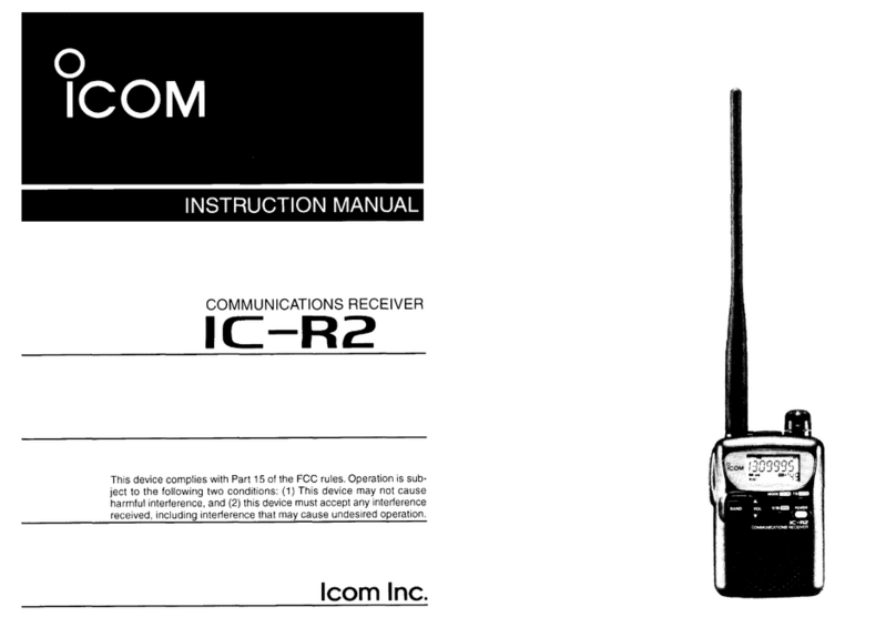
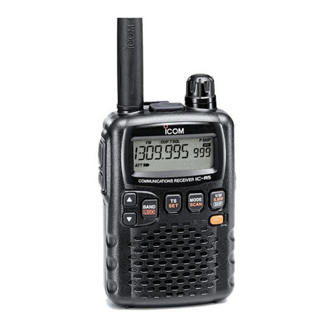
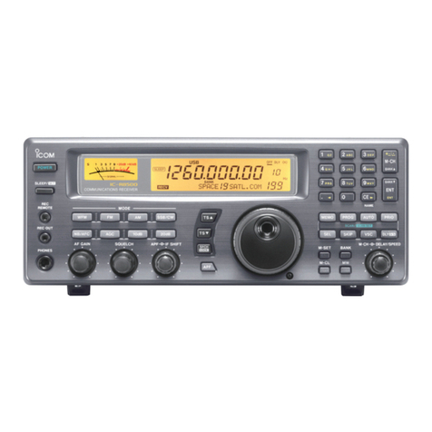
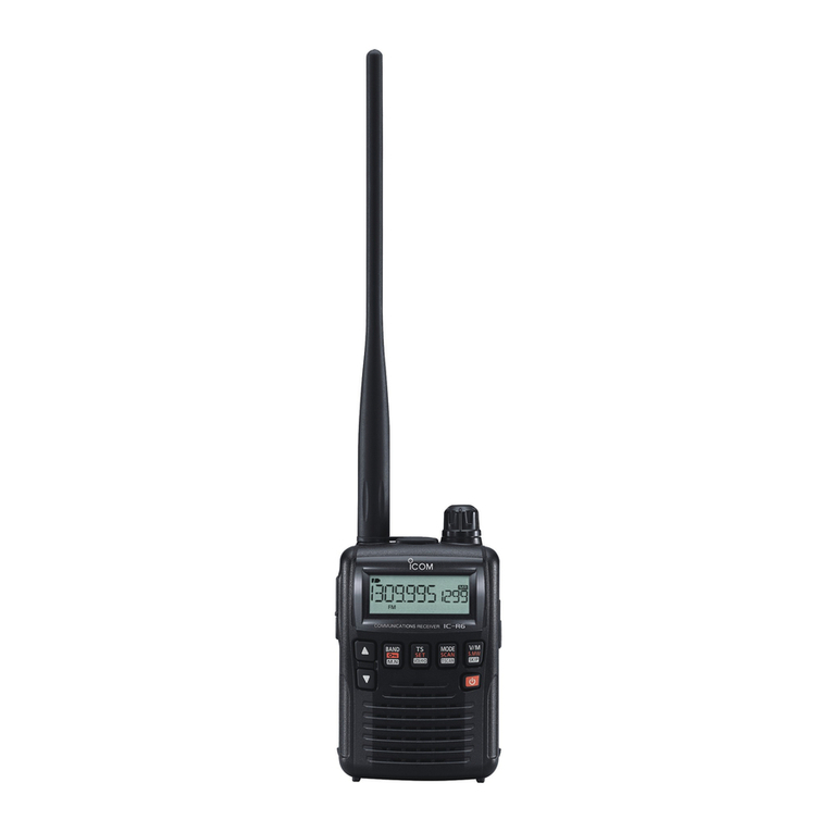
Icom IC-R100 User manual

е
СОМ
SERVICE
MANUAL
WIDEBAND
RECEIVER
IC-RIOO
Icom
Inc.

INTRODUCTION
This
service
manual
describes
the
latest
service
infor-
mation
for
the
IC-R100
VVIDEBAND
RECEIVER
at
the
time
of
going
to
press.
5
versions
of
the
IC-R100
have
been
designed.
This
service
manual
covers
each
version.
VERSION
NO.
VERSION
SYMBOL
m
|
To
upgrade
quality,
all
electrical
or
mechanical
parts,
and
internal
circuits
are
subject
to
change
without
notice
or
obligation.
DANGER
NEVER
connect
the
receiver
to
an
AC
outlet
or
to
a
DC
power
supply
that
uses
more
than
16
V.
This
will
ruin
the
receiver.
DO
NOT
expose
the
receiver
to
rain,
snow
or
any
liquids.
DO
NOT
reverse
the
polarities
of
the
power
supply
when
connecting
the
receiver.
DO
NOT
apply
an
RF
signal
of
more
than
20
dBm
(100
mW)
to
the
antenna
connector.
This
could
damage
the
receiver's
front
end.
UQUID
CRYSTAL
DISPLAY
ЕМ
АРС
aim
nni
UTLIULULILELI
PAUSE
MODE
пока
12
se
COMMUNICATIONS
RECEIVER
TC
-R1OO
ORDERING
PARTS
Be
sure
to
include
the
following
four
points
when
ordering
replacement
parts:
1.
10-digit
order
numbers
2.
Component
part
number
and
name
3.
Equipment
model
name
and
unit
name
4.
Quantity
required
«SAMPLE
ORDER»
1130001000
IC
UPD4066BC
—
IC-R100
MAIN
UNIT
5
pieces
8810006130
Screw
BiH
M2.6
x5
IC-R100
Top
cover
10
pieces
Addresses
are
provided
on
the
inside
back
cover
for
your
convenience.
REPAIR
NOTE
.
Make
sure
a
problem
is
internal
before
disassembling
the
receiver.
.
DO
NOT
open
the
receiver
until
the
receiver
is
dis-
connected
from
its
power
source.
.
DO
NOT
force
any
of
the
variable
components.
Turn
them
slowly
and
smoothly.
.
DO
NOT
short
any
circuits
or
electronic
parts.
An
insulated
tuning
tool
MUST
be
used
for
all
adjustments.
.
DO
NOT
keep
power
ON
for
a
long
time
when
the
receiver
is
defective.
.
READ
the
instructions
of
test
equipment
thoroughly
before
connecting
equipment
to
the
receiver.

SECTION
SECTION
SECTION
SECTION
SECTION
SECTION
SECTION
SECTION
SECTION
Ф
> A
A
b
a
a
RA
aan
о
~
لح
لح
لد
لح
оо
o o
со
ж
о N
~
о
со
+
G
N
一
ко
N
一
TABLE
OF
CONTENTS
SPECIFICATIONS
22222222222..........4222....2..2...
1—
1
INSIDE
VIEWS.
RR]
RR]
eee
ens
2—1
BLOCK
DIAGRAM
оон
Lees
od
a
E
арды
лы
URN
3—
1
CIRCUIT
DESCRIPTION
eem
4—1~8
RE
CIRCUITS.
vo
а
лкен
Rem
Se
eae
ak
ди
SES
4
一
1
IF
CIRCUITS:
оа
ERE
xU
e
eher
Бека
бады
ад
„=
о
4
一
2
PLL
СІНСІЛТ5...........................................................
Ц.
4--4
POWER
SUPPLY
CIRCUITS
.
e
hme
mrt
4—5
OTHER
СІНСІЛТ5............................................43л4л.2........Ш
Ж
4--6
LOGIC
СІНСІЛТ5.....................................................Ҙ0...а.
ЗУ
4--7
MECHANICAL
PARTS
AND
0І$АЅЅЕМВІҮ............................
5—1~3
FRONT
PARTS
.......................
hh
heh
hh
eme
hh
5
一
1
ACCESSORIES
................................................
........
as
5--1
CHASSIS
РАВТЗ................
GOES
edle
gU
ма
О
СЕТ
Ur
AE
5—2
PARTS
ET
а
аи
ои
аи
ақтар
ыны
ары
6—1~9
ADJUSTMENT
PROCEDURES
ea
7—1~8
PREPARATION
BEFORE
SERVICING.
........
cee
eee
tnt
7
一
1
TEST
EQUIPMENT
СОММЕСТІОМ.............................................
7—1
PLL
ADJUSTMENT
......
неее
еек"
7
一
2
RECEIVER
АРЈОЅТМЕМТ.
......
ee
ee
tte
eee
tees
7—3
BOARD
LAYOUTS
La
вон
a
bisce
eal
seeds
8-1-5
SUBORDINATE
LOGIC
ӘМІТ5........................................2....Д2ДШД...
8
—
1
MAIN
UNIT
.................
RR
Rh
eek
heran
8
一
3
PLE
UNIT
са
ОО
ie
да
к
а
алы
ОСО
ORE
eh
ы
dela
8—4
SUBORDINATE
PLL
UNITS
..................................................
8—5
VOLTAGE
DIAGRAM
|.
9—1
SECTION
1
SPECIFICATIONS
e
Frequency
coverage
e
Mode
е
Tuning
step
increments
e
Antenna
impedance
e
Power
Supply
requirement
e
Current
drain
(at
13.8
V
DC)
e
Usable
temperature
range
e
Frequency
stability
(at
1800
MHz):
e
Number
of
memory
channels
e
Dimensions
e
VVeight
e
Sensitivity
e
Selectivity
e
Audio
output
povver
e
Audio
output
impedance
VERSION
FREQUENCY
COVERAGE
U.S.A.,
Europe,
0.1--1856
MHz*
Australia
13.95—
14.5
MHz,
28.0—
29.7
MHz,
144.0
—
146.0
MHz,
430.0--440.0
MHz,
1240.0
--1300.0
MHz
0.1--87.5
MHz,
108.0--1856
MHz*
*Specifications
guaranteed
for
0.5--1800
MHz
AM,
FM,
Wide
FM
(WFM)
1,
5,
8,
10,
12.5,
20
ог
25
kHz
(100~521.5
kHz
and
1.630—
904.9995
MHz)
1,
5,
8, 9,
10,
12.5,
20
or
25
kHz
(522—
1629.5
kHz)
12.5,
20
ог
25
kHz
(905-1856
MHz)
50
Q
(unbalanced)
13.8
V
DCx
15
%
(negative
ground)
Less
than
1.1
A
—10
'C—
+60
°С
(+14
^F—
+140
°F)
+3.5
ppm
(0
'C—
+50
°C;
+32
°F~
+122
°F)
Memory
channels
100
Priority
channel
1
Scan
edge
channels
20
(for
10
scan
ranges)
150
(W)
x
50
(H)
x
181
(D)
mm
5.9
(VV)
x
2.0
(H)
x
7.1
(D)
in
(Projections
not
included)
1.4
kg
(3.1
Ib)
Frequenc
Germany
Еве
|
-一
saw
|
с
L
-
|
su
|
[
res
вање
|
mw
|
—
|
w
|
Measurement
conditions
:
Preamp
is
ON
in
the
50--904.9995
MHz
frequency
гапде.
FM
12
dB
SINAD
(1
kHz
modulation
with
+3.5
kHz
deviation)
WFM
12
dB
SINAD
(1
kHz
modulation
with
+50
kHz
deviation)
АМ
10
4В
5/М
(1
kHz
modulation
with
30
96
depth)
FM
More
than
15
RHz/—6
dB
VVFM
More
than
180
КН2/-3
dB
AM
More
than
6
kHz/—6
dB
More
than
2.5
VV
at
10
96
distortion
with
an
8
О
load.
4-8
О
All
stated
specifications
are
subject
to
change
without
notice
ог
obligation.

SECTION
2
INSIDE
VIEWS
e
TOP
VIEW
Switching
relay
circuit
IC7
ND487C1
tst
me
(Се
CB346M1B
50.0
一
905.0
MHz
Preamplifier
(IC2:
MC-5156)
ғазып-----
"MEN,
ЕЧ
d
f
FIL
1
UNIT
-
à
4
L
TUNER
UNIT
Reference
crystal
m
(X1:
CR316
12.6
MHz)
a
=
10
V
DC-DC
Converter
Pulse-swallow
counter
(IC5:
BA6161M)
(IC1:
M54562P)
Expander
(IC11:
LA7910)
e
BOTTOM
VIEW
FM
detector
circuit
(IC1:
MC3357P)
Lithium
backup
battery
Reference
crystal
(X1:
CR114
10.24
MHz)
AFC
circuit
(IC2:
BA695)
у
ircuit
арашы
WFM
detector
circuit
(СЗ:
MC3356P)
Analog
switching
circuit
AM,
ЕМ
1st
IF
circuit
(IC5:
uPD4066BC)

BLOCR
DIAGRAM
SECTION
3
LINO
NIV
LINN
Td

SECTION
4
CIRCUIT
DESCRIPTION
41
RF
CIRCUITS
4-1-1
FILTER
CIRCUIT
(PLL
UNIT)
The
IC-R100
has
3
antenna
connectors
(J7,
98,
J9)
for
a
super-wideband
receiving
range
of
0.1
MHz
to
1856.0
MHz.
Received
signals
enter
one
of
the
3
antenna
connectors
depending
on
the
receive
frequency
range.
(1)
0.1—50.0
MHz
FILTER
RF
signals
from
an
antenna
connector
(J8)
are
distributed
to
three
separate
filters
through
switching
diodes
(D10,
D12)
for
filter
selection.
*
0.1000—
1.6290
MHz
After
passing through
a
switching
diode
(D10)
a
0.1000—
1.6290
MHz
signal
is
applied
to
an
attenuator
consisting
of
R64~R66.
The
attenuator
prevents
distortion
of
very
strong
signals
from
medium
wave
broadcasting
stations.
The
signal
is
applied
to
FIL
1
(С1--С5,
11,
12)
which
forms
a
low-pass
filter.
The
filter
circuit
cuts
off
frequencies
of
1.6290
MHz
or
higher.
The
filtered
signal
passes
through
a
switching
diode
(D11).
•
1.6295--32.7495
MHz
After
passing
through
a
switching
diode
(012)
a
1.6295--32.7495
MHz
signal
is
applied
to
FIL
2
(C1—
C7,
L1,
L2)
which
forms
a
high-pass
filter.
The
filter
circuit
passes
frequencies
approx.
1.630
MHz
or
lower.
The
signal
is
applied
to
FIL
3
(С1--5,
11,
12)
which
forms
a
low-pass
filter.
The
filter
circuit
cuts
off
approx.
32.75
MHz
or
higher.
The
filtered
signal
passes
through
a
switching
diode
(D14).
|
32.7500--49.9995
MHz
A
32.7500
MHz~49.9995
MHz
signal
is
applied
to
FIL
2
through
the
switching
diode
(О12).
The
signal
is
applied
to
FIL
4
(C1~C9,
L1~L4)
which
forms
a
bandpass
filter.
The
bandpass
filter
passes
signal
within
the
frequency
range
of
32.7500~50.0000
MHz.
The
filtered
signal
is
applied
to
the
switching
diode
(D14).
е
RF
CIRCUITS
0,1--49,9995
MHz
0.1—1.8290
MHZ
1.6295--49.9995
MHz
1.6295
一
32.7495
MHz
(2)
50.0--905.0
MHz
FILTER
No
filter
is
installed
in
this
frequency
range.
RF
signals
enter
an
antenna
connector
(J7)
and
then
are
applied
to
the
RF
relay
circuit
(RL2,
RL3).
The
RF
relay
circuit
switches
the
signals
to
bypass
through
a
preamplifier
(С2)
ог
be
amplified
at
the
preamplifier.
The
pre-
amplifier
(IC2)
provides
15
dB
gain
to
attenuate
ап
IF
signal
level
at
an
attenuator
circuit
(Q16)
when
the
preamplifier
circuit
is
turned
ON.
(3)
905.0--1856.0
MHz
FILTER
RF
signals
enter
an
antenna
connector
(J9)
and
then
pass
through
a
switching
diode
(018).
The
signals
are
applied
to
two
separate
high-pass
filters
for
frequencies
lower
than
and
higher
than
1380.5
MHz.
The
filtered
signals
pass
through
a
switching
diode
(D21).
4-1-2
HF
BAND
CONVERTER
CIRCUIT
(PLL
UNIT)
The
filtered
signals
entering
at
J8
are
applied
to
a
1st
mixer
circuit
consisting
of
IC7,
L29,
L30
and
then
are
mixed
with
a
63.0
MHz
1st
LO
signal
to
produce
a
63.1
~112.9995
MHz
1st
IF
signal
corresponding
to
the
receive
frequency
range
ої
0.17-49.9995
MHz.
The
63.0MHz
1st
LO
signal
is
generated
by
a
local
oscillator
(X1,
Q1).
X1
produces
a
12.6
MHz
reference
frequency.
The
reference
frequency
is
multiplied
by
five
at
LO
amplifiers
(Q6,
Q15)
for
producing
the
63.0
MHz
1st
LO
signal.
4-1-3
1GHz
BAND
CONVERTER
CIRCUIT
(PLL
UNIT)
The
filtered
signals
entering
at
J9
are
applied
to
a
RF
amplifier
(IC8)
corresponding
to
a
UHF
band
and
then
applied
to
a
1st
mixer
circuit
(IC9).
IC9
is
a
DBM
(Double
Balanced
Mixer)
The
signals
are
mixed
with
a
475.5
905.0
MHz
1st
LO
signal
to
produce
a
429.5—
905.0
MHz
1st
IF
signal
corresponding
to
the
receive
frequency
range
of
905.0—
1856.0
MHz.
Тһе
475.5--905.0
MHz
1st
Lo
signal
is
buffer-amplified
at
IC10
depending
on
the
receive
frequencies.
The
signal
is
applied
to
the
1st
mixer
circuit
(IC9).
©?
1st
LO
signat
from
|016

4-2
IF
CIRCUITS
4-2-1
TUNER
UNIT
(PLL
UNIT)
The
TUNER
UNIT
(EP2)
contains
an
RF
amplifier
controlled
by
the
ТАСС
signal,
mixer
and
4
VCOs.
Тһе
RF
signals
are
applied
to
P2
on
the
TUNER
UNIT
(EP2)
to
be
con-
verted
to
а
46
MHz
IF
signal.
Тһе
TUNER
UNIT
(EP2)
outputs
the
signal
from
pin
8.
IC2
on
the
LOGIC
UNIT
supplies
2-bit
data
to
IC11
(pin
3,
4).
IC11
is
ап
expander
for
switching
the
operating
band
of
TUNER
UNIT
(EP2).
The
following
table
(Fig
2)
shows
the
relations
between
2-bit
data
and
the
band
signal.
H:
High
level
No
indication:
Lovv
level
4-2-2
AMIFM
IF
AND
2ND
MIXER
CIRCUITS
(MAIN
UNIT)
The
46
MHz
IF
signal
passes
through
a
switching
diode
(D1)
with
AM
5
and
FM
5
signals
when
AM
or
FM
mode
is
selected.
The
signal
is
applied
to
an
IF
amplifier
and
then
applied
to
a
crystal
filter
(ЕП)
to
improve
the
selectivity.
The
filtered
signal
is
applied
to
a
2nd
mixer
(Q2)
and
then
mixed
with
the
35.3
MHz
2nd
LO
signal
to
produce
a
10.7
MHz
2nd
IF
signal.
A
35.3
MHz
2nd
LO
signal
is
generated
by
a
2nd
local
oscillator
circuit
consisting
of
D8,
X3,
Q5,
and
other
components.
The
2nd
LO
oscillator
circuit
produces
a
frequency
step
less
than
the
PLL
reference
frequency.
The
LOGIC
UNIT
supplies
D/A
converted
signals
to
IC10
(pin
3)
which
correspond
to
each
tuning
step.
The
signals
are
amplified
at
IC10
and
then
applied
to
a
varactor
diode
(D8)
which
shifts
the
oscillation
frequency.
•
АМІЕМ
IF
AND
2ND
MIXER
CIRCUITS
46.0
MHz
10.7
MHz
Q1
IF
|
PLL
IC
signal
(IC1,
pin
16)
AM,
FM
35.3
MHz
signal
DIA
signal
from
LOGIC
UNIT
Fig.
3
4—2
4-2-3
2ND
IF
AND
FM
DEMODULATOR
CIRCUITS
(MAIN
UNIT)
The
10.7
MHz
2nd
IF
signal
is
applied
to
ҒІ2.
Fl2
is
а
MCF
(Monolithic
Crystal
Filter)
which
suppresses
out-of-
band
signals.
The
2nd
IF
signal
is
applied
to
a
3rd
mixer
section
of
IC1
and
is
mixed
vvith
a
3rd
LO
signal
to
be
converted
to
a
455
kHz
3rd
IF
signal.
IC1
is
designed
for
use
in
FM
dual
conversion
com-
munications
equipment.
IC1
contains
the
3rd
mixer,
local
oscillator
circuit,
limiter
amplifier,
quadrature
detector
circuit,
and
active
filter
circuit.
The
local
oscillator
section
and
X1
generate
10.245
MHz
for
a
3rd
LO
signal.
The
3rd
IF
signal
from
the
3rd
mixer
(IC1,
pin
3)
passes
through
a
ceramic
filter
(F13)
where
unwanted
signals
are
suppressed.
It
is
then
amplified
at
the
limiter
amplifier
section
(IC1,
pin
5)
and
applied
to
the
quadrature
detector
section
(IC1,
pin
8
and
ceramic
discriminator
X2)
to
demodulate
the
3rd
IF
signal
into
an
AF
signal.
The
AF
signal
is
output
from
IC1
(pin
9).
4-2-4
AM
DEMODULATOR
CIRCUIT
(MAIN
UNIT)
A
portion
of
the
455
kHz
3rd
IF
signal
is
applied
to
an
IF
amplifier
(Q4)
after
passing
through
the
ceramic
filter
(FI3)
when
AM
mode
is
selected
by
switching
diodes
(D5,
D7).
When
the
switching
diodes
are
turned
ON,
AM
5
signal
line
obtains
5
V.
The
amplified
signal
passes
through
a
ceramic
filter
(Fl4)
to
improve
selectivity.
The
filtered
signal
is
re-amplified
at
an
IF
amplifier
(Q7)
and
then
rectified
by
the
AM
detector
circuit
(D10,
D11).
The
detected
signal
is
demodulated
into
an
AM
signal.

e
2ND
IF
AND
ҒМ/АМ
DEMODULATOR
CIRCUITS
5.0У
I01
2nd
LO
AM5
line
AF
signal
signal
Fig.
4
4-2-5
WFM
DEMODULATOR
CIRCUIT
When
the
“WFM
5"
line
becomes
“HIGH”,
the
S-meter
(MAIN
UNIT)
switch
(Q9)
is
turned
ON
to
cut
off
the
FM
or
AM
signal.
The
46
MHz
IF
signal
is
applied
to
a
2nd
mixer
section
In
FM
or
AM
mode,
the
S-meter
signal
is
applied
to
IC4(b)
of
IC3
and
then
mixed
with
the
35.3
MHz
2nd
LO
signal
(pin
6)
through
the
ТАСС
signal
line.
Тһе
inverted
and
to
produce
а
10.7
MHz
2nd
IF
signal.
amplified
signal
is
applied
to
the
main
CPU
(IC2,
pin
93).
The
35.3
MHz
2nd
LO
signal
is
amplified
at
an
LO
When
the
"FM
5"
or
"AM
5"
line
becomes
"HIGH",
the
amplifier
(Q6)
and
is
then
applied
to
the
2nd
mixer
S-meter
switch
(Q10)
is
turned
ON
to
cut
off
the
WFM
section
through
IC3
(pin
3).
S-meter
signal.
IC3
is
designed
for
use
in
digital
data
communications
equipment.
IC3
contains
the
2nd
mixer,
local
oscillator
4-2-7
AGC
CIRCUIT
(MAIN
UNIT)
circuit,
limiter
amplifier
and
quadrature
detector
circuit.
In
FM
or
AM
mode,
the
signal
is
detected
to
obtain
AGC
vol
at
D1
D11
and
is
then
amplified
at
an
AGC
The
2nd
IF
signal
from
the
2nd
mixer
(IC3,
pin
5)
passes
age
ا
M
|
:
P
|
i
ih
h
ic
filter
(Е15)
wh
têd
апа!
amplifier
(Q11).
The
amplified
signal
is
distributed
to
a
des
i
È
SF
M
Va
put
i
SIE
"di
base
of
the
IF
amplifier
(Q1)
on
the
MAIN
UNIT
and
the
Suppressed..
DEAS
шеп-атриес
atthe:
р
ВЕ
amplifier
on
the
TUNER
UNIT
(EP2)
through
the
section
(IC3,
pin
7)
and
applied
to
the
quadrature
detector
TAGC
line
section
(IC3,
pin
11
and
ceramic
discriminator
X4)
to
|
ек
И
de
an
AF
signal.
The
AF
Іп
WFM
mode,
the
"WFM
5"
line
becomes
“HIGH”,
ЗОНА
IS
UPAR
ONE
(pin
13).
turning
ОМ
012.
Тһе
АСС
voltage
is
cut
off
when
Q12
is
turned
ON.
4-2-6
S-METER
CIRCUIT
(MAIN
UNIT)
When
the
scan
is
in
operation,
the
AGCR
signal
from
In
WFM
mode,
the
S-meter
signal
is
output
from
IC3
(pin
the
LOGIC
UNIT
turns
OFF
Q23.
C132
is
bypassed
to
14)
and
then
applied
to
IC4(a)
(pin
3).
The
amplified
reduce
the
AGC
time
constant.
signal
is
applied
to
a
main
CPU
(IC2,
pin
93).
e
МЕМ
DEMODULATOR
CIRCUIT
5.0
V
2nd
LO
signal
WFMS5
line
S-METER
MUTE
Q9
TAGC
Signal
SM
line
from
LOGIC
UNIT
(сз
S-Meter
АМР
signal
S-METER
MUTE
010
1st
IF
signal

4-2-8
SQUELCH
CIRCUIT
(MAIN
UNIT)
The
IC-R100
has
2
squelch
systems,
S-meter
squelch
and
noise
squelch.
The
noise
squelch
functions
in
FM
mode.
Some
of
the
noise
components
in
the
AF
signal
from
IC1
are
applied
to
IC1
(pin
10)
via
a
de-emphasis
circuit
(R17,
C28,
C29).
This
de-emphasis
circuit
is
an
integrated
circuit
vvith
frequency
characteristics
of
—6
dB/octave.
The
active
filter
section
in
IC1
amplifies
noise
components
of
frequencies
of
20
kHz
and
above,
and
outputs
the
resulting
signals
from
pin
11.
Output
signals
are
rectified
by
D2
and
D3,
and
converted
to
DC
voltage.
The
rectified
voltage
triggers
the
squelch
switch
(Q3)
and
then
is
applied
to
a
squelch
trigger
circuit
(IC1,
pin
12).
The
output
level
from
IC1
(pin
14)
becomes
"LOW"
and
turns
ON
D29.
The
AF
signal
is
muted
when
the
output
level
from
IC6(b)
(pin
7)
becomes
"LOW."
The
S-meter
squelch
functions
in
either
AM
or
WFM
mode.
The
S-meter
squelch
signal
from
IC1
(pin
11)
is
applied
to
IC6(a)
through
the
squelch
switch
(Q3)
to
compare
with
a
reference
voltage
controlled
by
R86
on
the
LOGIC
UNIT.
When
this
reference
voltage
level
is
higher
than
.the
S-meter
squelch
level
from
IC1
(pin
11),
028
is
turned
ON.
The
output
level
from
IC6(b)
(pin
7)
becomes
"LOW"
to
mute
an
AF
signal
line.
When
the
S-meter
squelch
is
in
operation,
Q19
is
turned
ON
to
cut
off
the
noise
squelch.
4-2-9
AFC
CIRCUIT
(MAIN
UNIT)
This
circuit
automatically
controls
the
receive
frequency
to
compensate
for
the
frequency
drift
in
FM
or
AM
mode.
IC2
is
a
monolithic
IC
which
lights
up
"AFC"
on the
function
display
when
AFC
function
is
in
operation.
A
current
regulator
(IC8)
supplies
a
10V
reference
voltage
to
IC2
(pin
1)
for
comparison
with
the
DC
component
in
the
detected
FM
or
AM
signal.
The
frequency
drift
selects
an
output
signal
to
control
the
receive
frequency.
The
signal
is
output
from
IC2
(pin
6—8)
and
applied
to
the
LOGIC
UNIT.
4-2-10
AF
AMP
CIRCUIT
(MAIN
UNIT)
The
de-modulated
signals
are
applied
to
an
AF
mute
circuit
consisting
of
IC5(b)~IC5(d)
and
then
amplified
at
015.
The
amplified
signals
are
applied
to
the
[VOL]
control
(R1)
on
the
VR
UNIT.
When
the
squelch
is
closed,
IC5
cuts
off
the
AF
signals
like
an
AF
mute
switch.
The
AF
signals
are
power-amplified
at
an
AF
power
amplifier
(IC7)
to
drive
a
speaker.
4-2-11
ANL
CIRCUIT
(MAIN
UNIT)
This
circuit
eliminates
the
noise
components
to
obtain
clear
reception
in
AM
mode.
4
一
4
The
ANL
circuit
consists
of
В70--В73,
012,
C69,
and
Q8.
The
detector
output
from
D10
and
D11
is
applied
to
the
anode
of
D12
through
R72
and
В73.
The
detector
output
is
also
applied
to
the
cathode
of
D12,
passing
through
R70
where
it
is
divided
by
R70
and
R71.
When
the
[AFC
*
ANL]
switch
is
turned
OFF,
the
anode
voltage
of
012
is
higher
than
the
cathode
voltage.
012
is
therefore
activated.
However,
when
the
[AFC
*
ANL]
switch
is
turned
ON,
the
ANL
signal
line
becomes
"HIGH"
to
turn
ON
08.
C69
and
C117
are
grounded.
Therefore
the
detector
output,
including
pulses,
is
only
applied
to
the
cathode
of
D12.
The
cathode
voltage
becomes
higher
than
the
anode
voltage
and
D12
shuts
OFF
just
at
the
moment
when
the
pulses
are
received.
The
AF
signal
(excluding
pulses)
then
passes
through
D12
and
is
applied
to
!С5(с).
*
ANL
CIRCUIT
Q8
069,
R72
D10
AM
signal
[AFC-ANL]
switch
(LOGIC
UNIT)
to
015
Fig.
6
AM5
line
4-3
PLL
CIRCUITS
4-3-1
GENERAL
(PLL
UNIT)
The
PLL
circuit,
using
a
one
chip
modulus
prescaler
(IC3),
directiy
generates
the
1st
LO
frequencies
vvith
4
VCO's
on the
TUNER
UNIT.
The
modulus
prescaler
(IC3)
sets
the
dividing
ratio
based
on
serial
data
from
the
CPU,
and
compares
the
phases
of
VCO
signals
and
the
reference
oscillator
frequency.
The
PLL
IC
(IC3)
detects
the
out-of-step
phase
and
outputs
it
from
IC3
(pin
5).
A
reference
frequency
is
oscillated
at
X1.
4-3-2
REFERENCE
OSCILLATOR
CIRCUIT
(PLL
UNIT)
A
12.6
MHz
reference
frequency
is
produced
by
the
local
oscillator
section
of
(СЗ
and
X1.
C14
provides
frequency
control.
4-3-3
LOOP
FILTER
CIRCUIT
(PLL
UNIT)
Phase-detected
signals
from
!C3
(pin
5)
are
converted
to
DC
voltage
by
a
loop
filter
consisting
of
an
active
filter
(Q2
and
Q3).
The
DC
voltage
(PLL
lock
voltage)
is
fed
back
to
the
TUNER
UNIT
(EP2)
through
an
LV
signal
line
to
control
the
VCO
oscillation
frequency.
The
unlock
signal
is
output
from
(СЗ
(pin
7).

50.0—905.0MHz
N
RF
О
О
905.0--1856.0
MHz
О
V
1st
LO
©
V
630MHz
SERIAL
DATA
x1
g
J
12.6
MHz
4-3-4
VCO
CIRCUIT
(PLL
UNIT)
Each
of
the
4
VCO's
oscillates
a
different
frequency
on
the
TUNER
UNIT
(EP2).
The
Fig.
7,
8
shows
the
relations
between
VCO
and
oscillation
frequency.
Fig.
8
The
signals
are
buffer-amplified
at
IC4
and
then
applied
to
IC3
(pin
8).
The
buffer
amplifier
(IC4)
protects
the
PLL
output
signal
against
VCO
oscillation.
4-3-5
DC-DC
CONVERTER
CIRCUIT
(PLL
UNIT)
IC5
is
a
DC-DC
converter
which
creates
approximately
30
V
DC
from
10
V
DC
to
obtain
wide
range
lock
voltages
for
the
PLL
circuit.
Fig.
7
TUNER
UNIT(EP2)
eae
1
کے
1
09
i
©
|
|
IF
OUT
I
І
45.995—
|
i
46.004
MHz
!
І
l
!
!
Гм
LOOP
FILTER
4-4
POWER
SUPPLY
СТВСЏТ5
4-4-1
VOLTAGE
LINES
LINE
DESCRIPTION
13.8
V
DC
controlled
by
the
PWS
signal
line.
5V
Common
5
V
converted
from
the
13.8
V
line
at
IC
9
on
the
MAIN
UNIT.
10
V
DC
converted
from
the
13.8
V
line.
IC8
on
the
MAIN
UNIT
is
a
switching
regulator
IC
and
converts
IC5
output
into
approx.
30
V
DC.
4-4-1
SWITCHING
CIRCUIT
(MAIN
UNIT)
This
circuit
consists
of
Q17,
Q18
and
Q30.
The
circuit
corresponds
to
the
high-rippled
DC
voltage
which
an
AC
adapter
contains.
When
a
ripple
is
present
in
DC
voltage,
a
ripple
filter
(C129,
R132)
eliminates
the
ripple
to
obtain
clear
reception.

4-4-2
5VAND
10V
REGULATOR
CIRCUITS
(MAIN
UNIT)
|
The
ОС
voltages
are
supplied
from
regulator
circuits
corresponding
to
the
voltages.
They
are
regulated
at
the
follovving
circuits
using
13.8V
DC.
(1)
5
V
REGULATOR
(MAIN
UNIT)
5V
DC
is
regulated
by
the
three-terminal
voltage
regulator
(IC9)
and
applied
to
the
MAIN
and
PLL
UNITS.
(2)
10
V
REGULATOR
(MAIN
UNIT)
10V
DC
is
regulated
by
the
three-terminal
voltage
regulator
(IC8)
and
applied
to
the
MAIN
and
PLL
UNITS.
e
5
V
AND
10
V
REGULATOR
CIRCUITS
HV
iine
[PUSH-ON/VOL]
CONTROL
POW
line
13.8
V
Fig.
9
4-4-3
CPU
POWER
SUPPLY
CIRCUIT
(LOGIC
UNIT)
The
DC
voltage
is
applied
to
the
main
CPU
(IC2,
pin
8)
via
D2
from
the
lithium
backup
battery
(BT1)
to
provide
backup
for
the
memory
contents
regardless
of
the
power
switch
condition.
e
CPU
POWER
SUPPLY
AND
CPU
RESET
CIRCUITS
LOG
5
line
Fig.
10
4-4-4
SUB
CPU
POWER
SUPPLY
CIRCUIT
(MAIN
AND
LOGIC
UNITS)
The
DC
voltage
is
applied
to
the
sub
CPU
(IC1,
pin
54)
from
the
lithium
backup
battery
(BT1)
to
provide
backup
for
the
memory
contents.
This
circuit
is
controlled
by
Q28.
*
SUB
CPU
POWER
SUPPLY
LOG
5
line
SBUP
line
to
LOGIC
UNIT
IC1
(pin
54)
Fig.
11
4-5
OTHER
CIRCUITS
4-5-1
DIMMER
CIRCUIT
(LOGIC
UNIT)
The
dimmer
circuit
consists
of
Q8,
Q9
and
other
components
and
drives
backlights
(DS2),
ensuring
that
brightness
does
not
change
even
with
a
change
of
power
supply.
When
the
main
CPU
(IC2,
pin
28)
changes
its
output
level,
Q8
and
Q9
change
the
base
voltage
and
collector
current.
When
the
main
CPU
(IC2,
pin
28)
outputs
"LOW",
the
base
of
Q9
obtains
5V
through
R89
to
light
up
DS2.
When
the
main
CPU
(IC2,
pin
28)
outputs
"HIGH"
to
turn
ON,
Q1,
R89
and
R90
divide
5
V
into
three
voltages.
The
three
voltage
portions
are
applied
to
the
base
of
Q9.
Therefore,
the
collector
voltage
from
Q8
decreases
to
dim
the
brightness
of
the
lamp
(DS2).
4-5-2
CPU
RESET
CIRCUIT
(LOGIC
UNIT)
When
the
power
switch
is
turned
OFF,
the
reset
circuit
functions
as
a
three-terminal
voltage
regulator
IC
(IC3)
which
resets
the
main
CPU
(IC2)
IC3
detects
+5
V
when
the
DC
voltage
is
applied
to
the
input
terminal
of
IC3
and
outputs
5
V.
The
voltage
of
the
leading
edge
is
applied
to
a
time
constant
(C55,
R93)
to
obtain
sufficient
reset
time
and
inverted
to
supply
a
reset
signal
to
the
main
CPU
(IC2,
pin
7)
at
Q12.
The
differential
circuit
(C54,
R84)
functions
while
an
AND
circuit
(D3
,
D5)
pushes
and
holds
the
[CLK],
[FUNC],
and
[ENT]
switches.
When
the
power
switch
is
turned
ON,
the
differential
circuit
outputs
a
pulse
to
reset
CPU.
4-5-3
REAL
TIME
CLOCK
(LOGIC
UNIT)
This
receiver
has
a
clock
IC
(IC1)
with
timer
function.
A
32.768
kHz
is
oscillated
at
X2
for
clock
reference.
When
the
power
switch
is
turned
OFF,
the
DC
voltage
is
applied
to
the
sub
CPU
(IC1)
from
the
lithium
battery
to
provide
backup
for
clock
operation.

46
LOGIC
CIRCUITS
(LOGIC
UNIT)
The
LOGIC
UNIT
has
two
CPUs
installed
as
main
and
sub
CPUs
for
a
variety
of
operating
functions.
4-6-1
MAIN
CPU
(IC2)
PORT
ALLOCATIONS
()
INPUT
PORT
DESCRIPTION
When
the
port
becomes
“LOW,”
the
CPU
detects
that
the
[0]
key
has
been
pushed.
When
the
port
becomes
“LOW,”
the
CPU
detects
that
the
[1]
key
has
been
pushed.
I
|
i
P14
When
the
port
becomes
"LOW,"
the
CPU
detects
that
the
[2]
key
has
been
pushed.
When
the
port
becomes
"LOW,"
the
CPU
detects
that
the
[3]
key
has
been
pushed.
When
the
port
becomes
"LOW,"
the
CPU
detects
that
the
[4]
key
has
been
pushed.
When
the
port
becomes
"LOW,"
the
CPU
detects
that
the
[5]
key
has
been
pushed.
When
the
port
becomes
"LOW,"
the
CPU
detects
that
the
[6]
key
has
been
pushed.
When
the
port
becomes
"LOW,"
the
CPU
detects
that
the
[7]
key
has
been
pushed.
When
the
port
becomes
"LOW,"
the
CPU
switches
to
Input
port
for
control
signals
to
communicate
with
the
sub
CPU.
"HIGH"
voltage
is
applied
to
the
terminal
every
second.
Input
port
for
the
DOWN
signal
of
the
main
dial.
Input
port
for
the
UP
signal
of
the
main
dial.
Ме
—_
ы
Р25
DUP
Input
port
for
serial
data.
K8
49
When
the
port
becomes
"LOW,"
the
CPU
detects
that
the
[B]
key
has
been
pushed.
PORT
|
PORT
PIN
NUMBER|
NAME
|NUMBER
DESCRIPTION
When
the
port
becomes
“LOW,”
the
CPU
detects
that
the
[9]
key
has
been
pushed.
When
the
port
becomes
"LOW,"
the
CPU
detects
that
the
[*]
key
has
been
pushed.
When
the
port
becomes
“LOW,”
the
CPU
detects
that
the
[ENT]
key
has
been
pushed.
KENT
When
the
port
becomes
“LOW,”
the
CPU
detects
that
the
[UP]
key
has
been
KUP
-
|
EES
ШЕ
~
~
>
о
When
the
port
becomes
“LOW,”
the
CPU
detects
that
the
[DOWN]
key
has
been
pushed.
>
о
When
(ће
port
becomes
"HIGH,"
the
CPU
detects
that
the
receiver
receives
signals.
When
the
port
becomes
"LOW,"
the
CPU
detects
that
the
power
switch
has
been
turned
ON.
BUSY
When
the
port
becomes
“LOW,”
the
CPU
detects
that
the
clock
switch
has
CLKS
been
turned
ON.
P70~
VER1~
67~69
|
Used
for
selecting
a
version
P72
VER3
when
only
the
CPU
is
reset.
i
AUTO
і
When
the
рогі
becomes
“LOW,”
the
9
kHz
step
of
the
U
P75
FDN
73
TS
function
is
selected.
This
TS
selection
is
only
possibe
after
the
CPU
has
been
reset.
AFC
control
signal
input.
When
the
port
becomes
"LOW,"
AFC
controls
the
receive
frequency
for
the
higher
frequency
direction.
ч
L3
AFC
control
signal
input.
When
the
port
becomes
"LOW,"
AFC
controls
the
receive
frequency
for
the
lower
fequency
direction.
74
AFC
control
signal
input.
When
the
port
becomes
“LOW,”
the
CPU
detects
that
the
displayed
frequency
(center
frequency)
has
been
received.
P76
FONT
AID
signal
input.
Used
for
indicating
signal
strength
on
the
S-indicator.
іа
РТО
SM
PT7
3

(2)
OUTPUT
PORT
PORT
|
PORT
PIN
|
NUMBER
|
NAME
|
NUMBER
DESCRIRHON
Р00--
DAO~
14~18
|
Output
D/A
converted
P04
DA4
signals
which
control
the
frequency
for
lower
10
kHz
unit.
POS
шы
Тһе
port
becomes
"HIGH"
ишан
when
АМ
mode
is
selected.
85
Outputs
a
strobe
signal
for
the
PLL
IC
chip.
SSTB
Outputs
a
strobe
signal
for
the
sub
CPU.
when
FM
mode
is
selected.
The
port
becomes
“HIGH”
when
МЕМ
mode
is
selected.
The
port
becomes
"HIGH"
square
vvaves
used
as
a
beep
tone.
Outputs
a
pulse
of
15џ5ес.
vvidth
vvhen
the
CPU
is
reset.
Output
band
control
signals.
See
the
table
shovvn
in
the
section.
The
port
becomes
"HIGH"
when
the
[PRE/ATT]
switch
is
pushed
опсе.
Outputs
serial
clock
Signals.
Outputs
serial
даѓа.
=
|
SRST
Outputs
1
kHz
or
500
Hz
јаз
The
port
becomes
"НІСН"
when
the
ГРВЕ/АТТ)
switch
is
pushed
tvvice.
The
port
becomes
“HIGH”
when
the
[PUSH-ON/VOL]
Switch
is
ON.
The
port
becomes
"HIGH"
when
the
[AFC
-
ANL]
switch
is
ON.
The
port
becomes
“HIGH”
when
the
[DIM]
switch
is
The
port
becomes
"LOW"
when
the
AGC
is
set
to
FAST
in
scanning
operation.
4-6-2
SUB
CPU
PORT
ALLOCATIONS
PORT
PORT
PIN
NUMBER
|
МАМЕ
|
NUMBER
DESCRIPTION
When
the
port
becomes
“LOW,”
the
CPU
enters
the
backup
mode.
Input
port
for
serial
clock
signals.
ы.
cum
EE
ЊЕ
Input
port
for
serial
data.
Input
port
for
a
strobe
signal.
This
port
becomes
"HIGH"
every
one
second.

SECTION
5
MECHANICAL
PARTS
AND
DISASSEMBLY
5-1
FRONT
PARTS
NUMBER
©
©
un
®
5-2
ACCESSORIES
LABEL
ORDER
|
@
|
8930013320
545
Rubber
|
@
|
8810006130
BiH
M2.6
x
5
ZK
||
@
|
8930018550
Sponge
(CG)
@
8110004010
8210005530
8830000550
|
©
|
8610006480
Knob
№152
[PUSH-ON/VOL]
[SQUELCH]
|
®
|
8610006470
|
Knob
№151
[TUNING
CONTROL]
10
Key
rubber
Blind
sheet
PH
BO
No.0-3
M14
x
4
Variable
resistor
RV—
168
[PUSH-ON/VOL]
Setscrew
(A)
M2.6
x
5
Encoder
EVQ-WQGF15
248
[TUNING
CONTROL]
Sub
chassis
LCD
holder
LCD
HLC9792-01-2300
LCD
filter
Screw
abbreviations
DESCRIPTION
QTY.
Top
cover
Front
panel
(inci.
window)
VR
nut
(E)
851
Reflector
BiH:
Binding
head
ZK:
Black
PH:
Pan
head
BO:
Self-tapping
f
З
V
YO
@@@@@|
ро
so
Јинеиневекртраненатаон
|
Lo
[sooo
[HE
vire
amerma
OPcO
—
|
+
|
perro
LO
[ойон
о
power
cable
ого
—
—
|
1
|
55997
Lo
sone
50
meuning
supp
rei
то
00008
ІП
ПИЕ
®
0000
@@@@
6€
|
®
|
8820000530
Mounting
bolt
|
©
|
8850000140
|
Flat
washer
МА
NI
BS
©
©
|49
[5210000040
|
Fuse
FGB
2A
|
@
[5610000020
|AP313
3.5@
CS
plug
|
@
|
8930018190
851
cable
tie
Се
ано“
Setscrew
M3
x
6
PH
(A)
ВО
M5
x
20
[
[sesso
|
Screw
abbreviations
РН: Pan
head
BS:
Brass
Ni:
Nickel
|
ВО:
Self-tapping
e
©
©
Flat
vvasher
М5
NI
BS
Spring
vvasher
М5
Ni

VR
UNIT
(B
2462A)
LOGIC
UNIT
(B
2460D)
TENKEY
UNIT
(B
2461B)

FIL
2
UNIT
(B
2599A)
>
(В
2598)
|
з
Ф
"поз
:
“|
MAIN
UNIT
(B
2458B)

5-3
CHASSIS
PARTS
LABEL
NUMBER
o
=
<
ORDER
DESCRIPTION
8930005360
8930017810
2510000470
8110004020
8810006130
8930001540
8010009920
8930018370
8810003350
`
8930018570
8930018580
8850000420
8930007430
8810002110
8810003150
8010009870
8930001160
8510000020
6450000970
6510000360
6510000410
6510000360
8810002160
8810003150
8410001500
8810000240
8830000100
8810003150
8010009880
Sponge
833
SP
plate
Speaker
EAS-6P100SA
Bottom
cover
BiH
M2.6
x
5
ZK
uL
ШИН
Sponge
(2)
Chassis
Tuner
base
cover
Setscrew
(C)
M3
x
5
Rubber
sheet
Standoff
(ВВ)
Spring
washer
M3
NI
Shield
plate
ЕН
М2.6
х
5
Setscrew
(А)
МЗ
х
5
Back
panel
(top)
Ground
spring
194
shield
case
ANT
connector
HSJ0914-01-140
[ANT
SEL)
ANT
connector
NR-DS-E
02
(БОМН2--905МН2)
ANT
connector
MR-DS-E
02
[0.5MHz—50MHz]
ANT
connector
NR-DS-E
02
(905МН2--1800МН2)
ЕН
M3
x
5
Setscrew
(A)
МЗ
х
5
MAIN
heatsink
РН
M3
х
8
Nuts
M3
Setscrew
(A)
M3
x
5
Back
panel
(bottom)
т
rear
rep
Screw
abbreviations
ВІН:
Binding
head
ZK:
Black
PH: Рап
head
МІ:
Nickel
FH:
Flat
head

SECTION
6
PARTS
LIST
[VR
UNIT]
ORDER
7210001840
RV-168
(RK0971112)
[PUSH-ON/OFF]
B
2462A
(VR)
Variable
Resistor
0910025801
|
P.C.
Board
[TENKEY
UNIT]
ORDER
Й
0910025912
|
Р.С.
Воага
В
24618
(TENKEY)
[LOGIC
UNIT]
ORDER
1140001260
|
IC
hPD75304GF-084-3B
9
1140001570
|
С
uPD78224GJ-533-5B
G
1110001550
S-8054ALB-LM-T1
1590000420
1590000420
1590000450
1530000160
1510000110
1590000420
1510000110
1530000160
1530000160
ВМ1404
(TE85R)
RN1404
(TE85R)
ЕМС4
7148
25С2712-Ү
(TE85R)
2SA1162-Y
(ТЕ85Ң)
ВМ1404
(TE85R)
25А1162-Ү
(ТЕ85В)
25С2712-Ү
(TE85R)
25С2712-Ү
(TE85R)
Transistor
Transistor
Transistor
Transistor
Transistor
Transistor
Transistor
Transistor
Transistor
1750000030
1750000020
1750000040
1750000020
Diode
Diode
Diode
Diode
155187
(TE85R)
155184
(TE85R)
155190
(TE85R)
155184
(TE85R)
CR-245
DT-26S
32.768KHZ
CSA9.21MT2
6050005090
6050005800
6060000190
Crystal
Crystal
Crystal
7030000300
|
Resistor
MCR10EZHJ
2200
(221)
7030000580
|
Resistor
MCR10EZHJ
47
КО
(473)
7030000580
|
Resistor
MCR10EZHJ
47
kQ
(473)
7030000580
|
Resistor
MCR10EZHJ
47
kQ
(473)
7030000620
|
Resistor
MCR10EZHJ
100
КО
(104)
7030000580
|
Resistor
MCR10EZHJ
47
КО
(473)
7030000580
|
Resistor
MCR10EZHJ
47
КО
(473)
7030000580
|
Resistor
MCR10EZHJ
47
КО
(473)
[LOGIC
UNIT]
7030000580
7030000580
7030000580
7030000970
7030000580
7030000580
7030000580
7030000500
7030000580
7030000620
7030000580
7030000580
7030000580
7030000580
7030000580
7030000580
7030000580
7030000580
7030000580
7030000580
7030000580
7030000580
7030000580
7030000580
7030000580
7030000580
7030000580
7030000580
7030000580
7030000580
7030000580
7030000580
7030000580
7030000380
7030000380
7030000380
7030000380
7030000380
7030000380
7030000380
7030000380
7030000380
7030000380
7030000380
7030000380
7030000380
7030000380
7030000380
7030000380
7030000380
7030000380
7030000380
7030000380
7030000380
7030000380
7030000380
7030000380
7030000380
7030000380
7030000380
7030000380
7030000380
7030000380
Resistor
Resistor
Resistor
Resistor
Resistor
Resistor
Resistor
Resistor
Resistor
Resistor
Resistor
Resistor
Resistor
Resistor
Resistor
Resistor
Resistor
Resistor
Resistor
Resistor
Resistor
Resistor
Resistor
Resistor
Resistor
Resistor
Resistor
Resistor
Resistor
Resistor
Resistor
Resistor
Resistor
Resistor
Resistor
Resistor
Resistor
Resistor
Resistor
Resistor
Resistor
Resistor
Resistor
Resistor
Resistor
Resistor
Resistor
Resistor
Resistor
Resistor
Resistor
Resistor
Resistor
Resistor
Resistor
Resistor
Resistor
Resistor
Resistor
Resistor
Resistor
Resistor
Resistor
MCR10EZHJ
MCR10EZHJ
MCR10EZHJ
MCR10EZHJ
MCR10EZHJ
MCR10EZHJ
MCR10EZHJ
MCR10EZHJ
MCR10EZHJ
MCR10EZHJ
MCR10EZHJ
MCR10EZHJ
MCR10EZHJ
MCR10EZHJ
MCR10EZHJ
MCR10EZHJ
MCR10EZHJ
MCR10EZHJ
MCR10EZHJ
MCR10EZHJ
MCR10EZHJ
MCR10EZHJ
MCR10EZHJ
MCR10EZHJ
MCR10EZHJ
MCR10EZHJ
MCR10EZHJ
MCR10EZHJ
MCR10EZHJ
MCR10EZHJ
MCR10EZHJ
MCR10EZHJ
MCR10EZHJ
MCR10EZHJ
MCR10EZHJ
MCR10EZHJ
MCR10EZHJ
MCR10EZHJ
MCR10EZHJ
MCR10EZHJ
MCR10EZHJ
MCR10EZHJ
MCR10EZHJ
MCR10EZHJ
MCR10EZHJ
MCR10EZHJ
MCR10EZHJ
MCR10EZHJ
MCR10EZHJ
MCR10EZHJ
MCR10EZHJ
MCR10EZHJ
MCR10EZHJ
MCR10EZHJ
MCR10EZHJ
MCR10EZHJ
MCR10EZHJ
MCR10EZHJ
MCR10EZHJ
MCR10EZHJ
MCR10EZHJ
MCR10EZHJ
MCR10EZHJ
DESCRIPTION
47
kQ
(473)
47
КО
(473)
47
КО
(473)
22
МО
(225)
47
КО
(473)
47
КО
(473)
47
КО
(473)
10
КО
(103)
47
kQ
(473)
100
ка
(104)
47
КО
(473)
47
КО
(473)
47
КО
(473)
47
КО
(473)
47
КО
(473)
47
КО
(473)
47
КО
(473)
47
КО
(473)
47
КО
(473)
47
КО
(473)
47
КО
(473)
47
КО
(473)
47
КО
(473)
47
КО
(473)
47
КО
(473)
47
КО
(473)
47
КО
(473)
47
КО
(473)
47
КО
(473)
47
КО
(473)
47
КО
(473)
47
КО
(473)
47
КО
(473)
1
ко
(102)
1
KO
(102)
1
КО
(102)
1
КО
(102)
4
КО
(102)
1
ко
(102)
1
КО
(102)
1
КО
(102)
1
КО
(102)
1
КО
(102)
1
RQ
(102)
1
КО
(102)
1
RQ
(102)
1
КО
(102)
1
RQ
(102)
1
КО
(102)
1
КО
(102)
1
КО
(102)
1
КО
(102)
1
RQ
(102)
1
ка
(102)
4
КО
(102)
1
ка
(102)
1
КО
(102)
1
КО
(102)
1
КО
(102)
1
КО
(102)
1
ко
(102)
`
1
КО
(102)
1
ко
(102)

[LOGIC
UNIT]
ORDER
7030000380
|
Resistor
MCR10EZHJ
1
КО
(102)
7030000380
|
Resistor
MCR10EZHJ
1
КО
(102)
7030000380
|
Resistor
MCR10EZHJ
1
КО
(102)
7030000380
|
Resistor
MCR10EZHJ
1
КО
(102)
7030000380
|
Resistor
MCR10EZHJ
1
КО
(102)
7030000380
|
Resistor
MCR10EZHJ
1
КО
(102)
7030000380
|
Resistor
MCR10EZHJ
1
КО
(102)
7030000380
|
Resistor
MCR10EZHJ
1
КО
(102)
7030000380
|
Resistor
MCR10EZHJ
1
КО
(102)
7410000520
|
Resistor
Array
RKM7L
104Ј
7030000580
|
Resistor
MCR10EZHJ
47
КО
(473)
7210001830
|
Variable
Resistor
RV-167
(RK09K)
7030000410
|
Resistor
MCR10EZHJ
1.8
КО
(182)
7030000390
|
Resistor
MCR10EZHJ
1.2
КО
(122)
7030000550
|
Resistor
MCR10EZHJ
27
КО
(273)
7030000590
|
Resistor
MCR10EZHJ
56
КО
(563)
7030000660
|
Resistor
MCR10EZHJ
220
КО
(224)
7030000620
|
Resistor
MCR10EZHJ
100
КО
(104)
7030000580
|
Resistor
MCR10EZHJ
47
КО
(473)
7030000660
|
Resistor
MCR10EZHJ
220
КО
(224)
7030000660
|
Resistor
MCR10EZHJ
220
КО
(224)
7030000620
|
Resistor
MCR10EZHJ
100
КО
(104)
7030000550
|
Resistor
MCR10EZHJ
27
КО
(273)
7030000500
|
Resistor
MCR10EZHJ
10
КО
(103)
[LOGIC
UNIT]
ORDER
4030004740
C2012
УВ
1H
472K-
T.
4030004740
C2012
JB
1H
472K-
MA
4030004740
C2012
JB
1H
472K-
T-A
4030004740
C2012
JB
1H
472K-
Т-А
4030004720
C2012
JB
1H
102K-
T-A
4510001150
50
MS7
R47
uF
4030004740
C2012
JB
1H
472K-
T-A
4030004740
C2012
JB
1H
472K-
T-A
4030004740
C2012
JB
1H
472K-
Ceramic
Ceramic
Ceramic
Ceramic
Ceramic
Electrolytic
Ceramic
Ceramic
Ceramic
HLC9792-01-2300
HRS-7219A
LCD
Lamp
5030000530
5080000150
EVQ-WQGF15
24B
[TUNING
CONTROL]
2250000050
|
Encoder
3020000130
|
Lithium
Battery
CR3032-1T2
P.C.
Board
B
2460D
(LOGIC)
LCD
contact
strip
SRCN-851
0910025784
8930017610
4030004520
|
Ceramic
C2012
SL
1H
220J-
Т-А
4030004520
|
Ceramic
C2012
SL
1H
220J-
Т-А
4030000920
|
Ceramic
GRM40
CH
150Ј
50P
T
4030000920
|
Ceramic
GRM40
CH
150J
50P
T
4030004760
|
Ceramic
C2012
JF
1E
104Z-
Т-А
4030004760
|
Ceramic
C2012
JF
1E
104Z-
T-A
4030004610
|
Ceramic
C2012
SL
1H
101Ј-
T-A
4030004610
|
Ceramic
C2012
SL
1H
101J-
T-A
4030004740
|
Ceramic
C2012
JB
1H
472K-
T-A
4030004740
|
Ceramic
C2012
JB
1H
472K-
T-A
4030004740
|
Ceramic
C2012
JB
1H
472K-
T-A
4030004740
|
Ceramic
C2012
JB
1H
472K-
T-A
4030004740
|
Ceramic
C2012
JB
1H
472K-
T-A
4030004740
|
Ceramic
C2012
JB
1H
472K-
T-A
4030004740
|
Ceramic
C2012
JB
1H
472K-
T-A
4030004740
|
Ceramic
C2012
JB
1H
472K-
T-A
4030004740
|
Ceramic
C2012
JB
1H
472K-
T-A
4030004740
|
Ceramic
C2012
JB
1H
472K-
T-A
4030004740
|
Ceramic
C2012
JB
1H
472K-
T-A
4030004740
|
Ceramic
C2012
JB 1H
472K-
T-A
4030004740
|
Ceramic
C2012
JB
1H
472K-
T-A
4030004740
|
Ceramic
C2012
JB
1H
472K-
T-A
4030004740
|
Ceramic
C2012
JB
1H
472K-
T-A
4030004740
|
Ceramic
C2012
JB
1H
472K-
T-A
4030004740
|
Ceramic
C2012
JB
1H
472K-
T-A
4030004740
|
Ceramic
C2012
JB
1H
472K-
T-A
4030004740
|
Ceramic
C2012
JB
1H
472K-
T-A
4030004740
|
Ceramic
C2012
JB
1H
472K-
T-A
4030004740
|
Ceramic
C2012
JB 1H
472K-
T-A
4030004740
|
Ceramic
C2012
JB
1H
472K-
T-A
4030004740
|
Ceramic
C2012
JB 1H
472K-
T-A
4030004740
|
Ceramic
C2012
JB
1H
472K-
T-A
4030004740
|
Ceramic
C2012
JB
1H
472K-
T-A
4030004740
|
Ceramic
C2012
JB
1H
472K-
T-A
4030004740
|
Ceramic
C2012
JB
1H
472K-
T-A
4030004740
|
Ceramic
C2012
JB
1H
472K-
T-A
4030004740
|
Ceramic
C2012
JB
1H
472K-
T-A
4030004740
|
Ceramic
C2012
JB
1H
472K-
T-A
4030004740
|
Ceramic
C2012
JB
1H
472K-
T-A
4030004740
|
Ceramic
C2012
JB 1H
472K-
T-A
4030004740
|
Ceramic
C2012
JB 1H
472K-
[MAIN
UNIT]
1110000630
1110001160
1110002010
1120001690
1130001000
1120001690
1110001360
1180000590
1110002020
1120001690
1180000010
1530002210
1580000110
1530000591
1530000150
1530000591
1530000591
1530000150
1590000350
1590000350
1590000350
1530002710
1590000350
1590000370
1530000110
1530000591
1540000200
1590000350
1590000350
Transistor
FET
Transistor
Transistor
Transistor
Transistor
Transistor
Transistor
Transistor
Transistor
Transistor
Transistor
Transistor
Transistor
Transistor
Transistor
Transistor
Transistor
MC3357P
BA695
MC3356P
M5223L
hPD4066BC
M5223L
hPC1242H
TA78DL10S
TA7805S
M5223L
TA78L005AP
2SC3776-D
3SK74
M
2SC2785
EL
25С2668-О
25С2785
EL
25С2785
EL
25С2668-О
ВМ1204
RN1204
RN1204
2SC2785
KL
RN1204
RN2204
2SC2458-GR
2SC2785
EL
2SD1406
Y
RN1204
RN1204
ORDER
Other manuals for IC-R100
5
Table of contents
Other Icom Receiver manuals

Icom
Icom IC-R6 User manual

Icom
Icom IC-R2 User manual

Icom
Icom IC-PCR1000 User manual

Icom
Icom IC-R20 User manual

Icom
Icom IC-A110EURO Installation and operating instructions

Icom
Icom MXA-5000 User manual

Icom
Icom IP501H User manual

Icom
Icom COMMUNICATIONS RECEIVER IC-R3 User manual

Icom
Icom COMMUNICATIONS RECEIVER IC-R3 User manual

Icom
Icom IC-RP1510 User manual