Hamworthy Stratton mk3 User manual

Stratton mk3
80-150 kW Frame and Header Kits Manual
IMPORTANT NOTE
THESE INSTRUCTIONS MUST BE READ
AND UNDERSTOOD BEFORE INSTALLING,
COMMISSIONING, OPERATING OR
SERVICING EQUIPMENT
UIN 233247 A03

2
80-150 kW Frame & Header Kits Manual
This kit is suitable for the following boilers:
Stratton mk3 80,100,120 & 150 using Natural Gas and 80,100 & 120 using Propane
IMPORTANT
THESE KITS CAN BE USED IN CONJUNCTION WITH
LOW LOSS HEADERS & PLATE HEAT EXCHANGERS
SUPPLIED AS PART OF THE STRATTON MK3 OPTIONS RANGE
CONTENTS
1 Introduction.....................................................................3
2 General Description of Systems ...................................3
3 Multiple Boiler System Components............................6
4 Frame Kit Installation Procedure ..................................9
5 Header Kit Assembly....................................................10
6 Installation Drawings for Multiple Boiler Systems....13
7 Electrical Connections & Wiring Diagram..................20
8 Commissioning and Testing........................................22
Boiler Water Header Size Maximum No. Boilers
in Cascade
Maximum Output
in Cascade (kW)
S3-80 DN80 4 320
S3-100 DN80 4 400
S3-120 DN80 3 360
S3-150 DN100 3 450
Stratton mk3 - DISCLAIMER
Not all cascades included in this manual are available at initial product launch.
For availability refer to the table below:
Note: This information will be updated in the next revision of this manual.

3
80-150 kW Frame & Header Kits Manual
1 INTRODUCTION
This technical data contains information for dimensioning & assembly
of a cascade system kit for the Stratton mk3.
Frame and header kits are available 'in line' congurations only.
GENERAL DESCRIPTION OF FRAME & HEADER KITS
A requirement to spread the total required heat output over several
boilers can be accommodated by the use of the Hamworthy multiple
boiler frame & header kit options.
All headers and pipe work should be insulated in accordance
with the Non Domestic Building Services Compliance Guide. To
ensure compliance with the maximum heat loss criteria, insulation
thickness should be calculated according to BS EN ISO 12241 using
standardised assumptions.
2.1 FRAME AND HEADER KIT DESIGN OPTIONS
The Stratton mk3 boilers are suitable for use in a multiple boiler conguration. The Stratton mk3 multiple boiler system is
available in side by side and giving the opportunity to choose the optimum footprint size or wall space for a given output. 80-150
kW kits include the support frame. Boilers can be wall mounted required.
2 GENERAL DESCRIPTION OF SYSTEMS
continued . . . . .
Available Rig Congurations Total Output
Required kW
Number of boilers
and Frames
Footprint Size
W x D x H (mm)
Frame and Header
Kit
Range Size Prod. No
Single Frame Congurations 80-120 1 500 x 704 x 1535 DN80 232865
Twin Frame Congurations 160-240 2 1000 x 704 x 1535 DN80 232866
Triple Frame Congurations 240-360 3 1500 x 704 x 1535 DN80 232867
Quad Frame Congurations 320-480 4 2000 x 704 x 1535 DN80 232868
Five Frame Congurations 400-600 5 2500 x 704 x 1535 DN80 232869
Six Frame Congurations 480-600 6* 3000 x 704 x 1535 DN80 232870
Available Rig Congurations Total Output
Required kW
No of boilers
and Frames
Footprint Size
W x D x H (mm)
Size Frame and
Header Kit
Range No sep/
LLH
PHEX
sep
Single Frame Congurations 150 1 500 x 794 x 1830 DN100 235371 232871
Twin Frame Congurations 300 2 1000 x 794 x 1830 DN100 235372 232872
Triple Frame Congurations 450 3 1500 x 794 x 1830 DN100 235373 232873
Quad Frame Congurations 600 4 2000 x 794 x 1830 DN100 235374 232874
Five Frame Congurations 750 5 2500 x 794 x 1830 DN100 235375 232898
Six Frame Congurations 900 6 3000 x 794 x 1830 DN100 235376 232899
Note. All boilers need to be sized in accordance to the total required heat load and the modulation capabilities of the appliances.
* Max 6 x 100 kW only. H=Height from oor to top of frame, D=Depth from installed wall to front of kit, W=Width of installed kit
DN80 DN100
232876 232877
kW Product No.
Stratton mk3 80 AA082638
Stratton mk3 100 AA082639
Stratton mk3 120 AA082640
Stratton mk3 150 AA082641
Table 1 80-120 kW
Table 2 150 kW only
Table 3 Available Stratton mk3 Boilers Table 4 Low Loss Header Accessories

4
80-150 kW Frame & Header Kits Manual
Product Number Frame and Header Size PHEX kW
232893 DN80 150
232894 DN80 300
232895 DN80 450
232896 DN80 300
236388 DN100 300
236389 DN100 450
232902 DN100 600
232897 DN100 750
232904 DN100 900
System separation PHEX kits are oered at the below kW ratings and are supplied with suitable pipe spools for connection to
frame and header kits.
Table 5 System Seperation PHEX Kits

5
80-150 kW Frame & Header Kits Manual
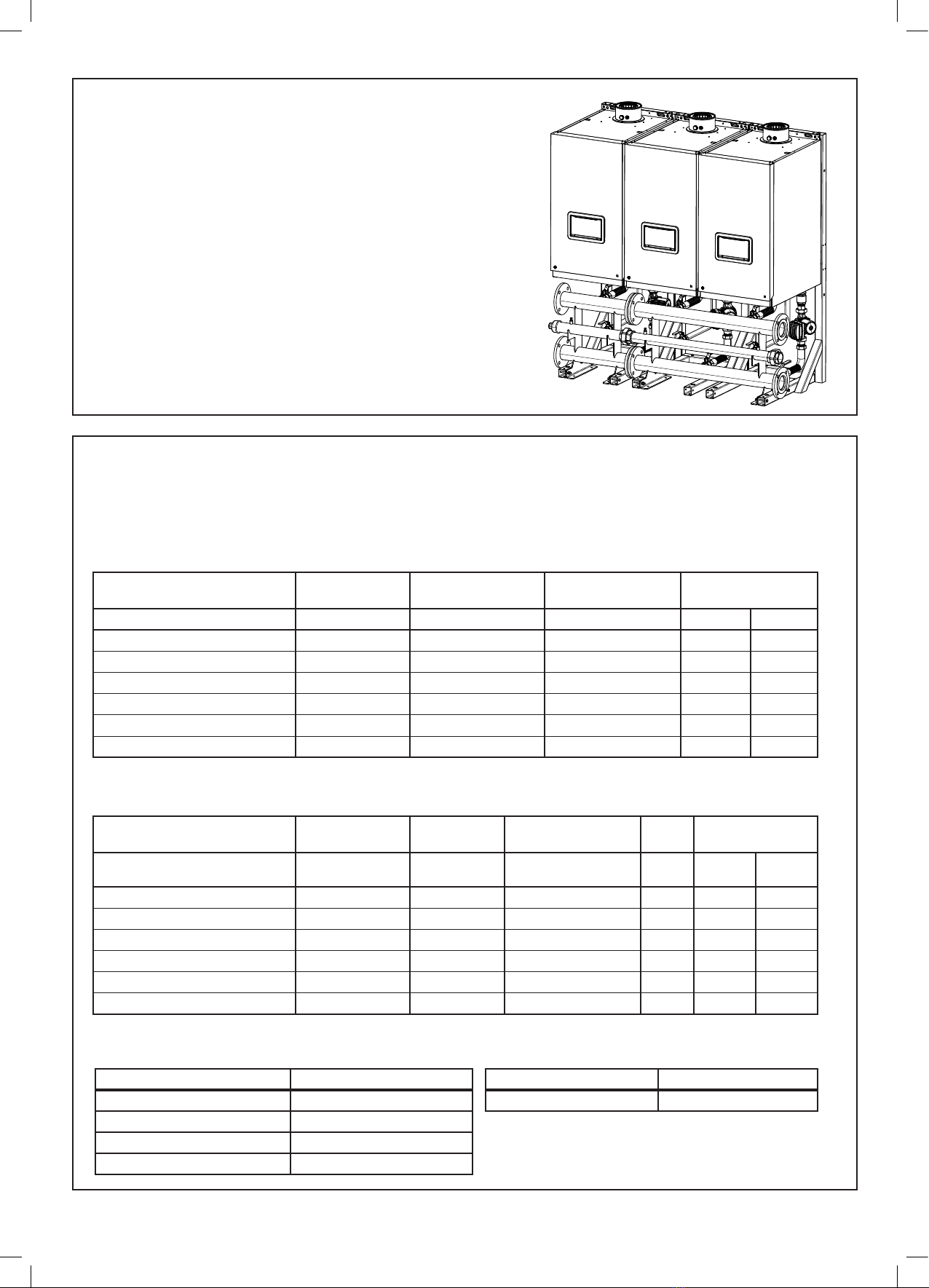
2.2 MULTIPLE BOILER INSTALLATIONS
The product range includes water and gas headers capable of assembly using threaded socket, compression and PN6 ange
connections.
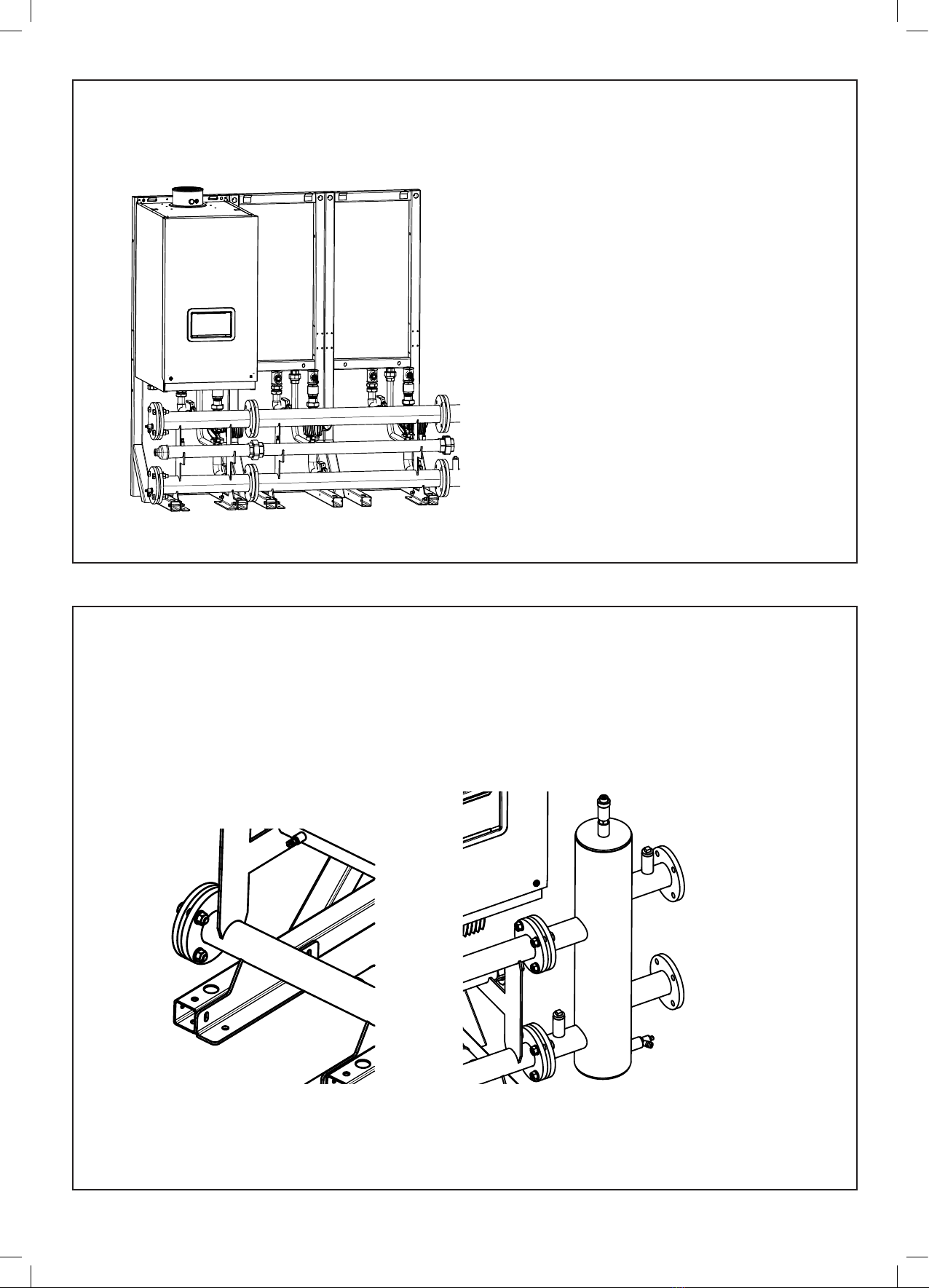
2.3 HYDRONIC ISOLATION: LOW LOSS HEADER & PLATE HEAT EXCHANGER
A low loss header or plate heat exchanger allows ow separation within a hydronic system.
This allows two ow circuits to operate with their own ow and pressure drop environments whilst eectively transferring heat to its
adjoined water circuit.
This enables the modern high resistant, high eciency boilers to operate under their optimum conditions, while the main heating circuit
operates to its own controlled optimum requirements.
2.4 OUTPUT CONTROL
All pumps should be wired to the appliance to allow a controlled pump over run.
If using an external pump control system the capability of a timed pump over run signal provided by the appliance must be maintained
at all times.
2.5 GAS SUPPLY
For Stratton mk3 the 80, 100, 120 & 150 boilers are congured for use with natural gas, or 80,100 & 120 running on Propane.
Connection to the gas supply must be in accordance to with all the applicable regulations.
The water header kits are supplied with a 2” gas header and associated components and hoses to make the connection to the
appliance.
Note. Test points are provided at each end of the 2” gas header. The test point nearest to the gas inlet is intended to be used as the
appliance inlet pressure point.
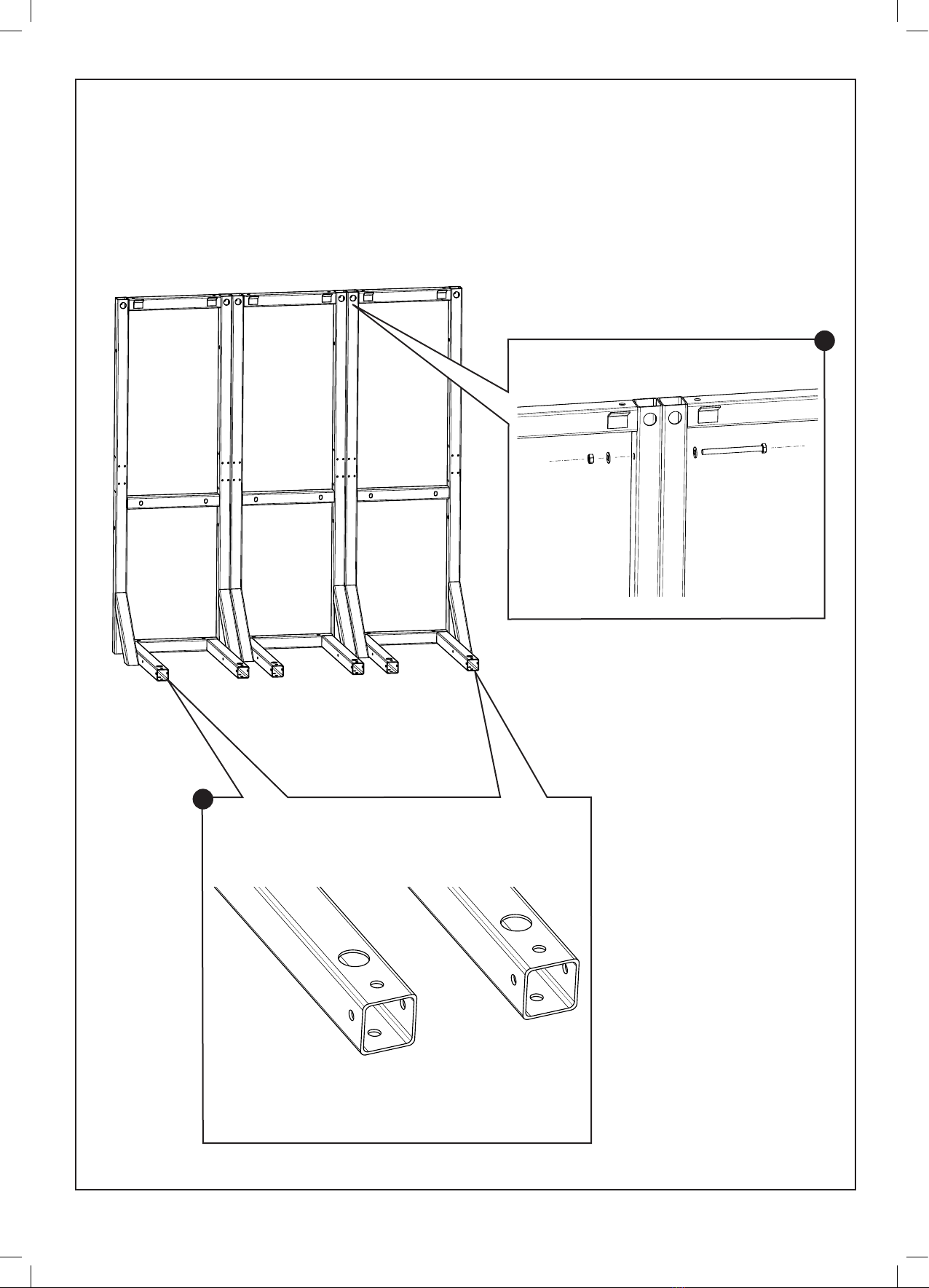
2.6 ASSEMBLY
The frames must be located in a suitable place that aords a at and level oor-area of suitable load bearing capacity. Care must be
taken when locating the frames that space is available for the servicing, installation and maintenance of the appliance and all of the
associated connections and equipment. (See Appliance manuals)
When using multiple frames they must be bolted together and secured to the oor.
2.7 SAFE HANDLING
Installation may require 2 or more operatives to move it to its installation site, remove it from its packaging base and during movement into its
installation location. Manoeuvring may include the use of a sack truck and involve lifting, pushing and pulling.
Caution should be exercised during these operations.
Operatives should be knowledgeable in handling techniques when performing these tasks and the following precautions should be considered:
• Grip the boiler at the base.
• Be physically capable.
• Use personal protective equipment as appropriate, e.g. gloves, safety footwear.
During all manoeuvres and handling actions, every attempt should be made to ensure the following unless unavoidable and/or the
weight is light:
• Keep back straight.
• Avoid twisting at the waist.
• Avoid upper body/top heavy bending.
• Always grip with the palm of the hand.
• Use designated hand holds.
• Keep load as close to the body as possible.
• Always use assistance if required.

6
80-150 kW Frame & Header Kits Manual
3 MULTIPLE BOILER SYSTEM COMPONENTS
3.1 GENERAL
The multiple boiler systems consist of the following components:
• Pipekit (1 and 2 wide congurations)
• Boiler gas header.
• Boiler ow and return headers supported on mounting skid
• Low loss mixing header (optional)
• Hardware pack (includes essential connection and valve components)
• Circuit extension kits (optional)
• Plate Heat exchanger kit (optional)
• Boiler pump
3.2 MAIN WATER HEADERS
The main water headers consist of: water ow, water return headers custom sized for all boilers. It is possible to extend the system to a
maximum of 6 boilers in a linear conguration.
Each header kit provides water ow and return headers sized either DN80 or DN100 dependent on total maximum combined heating
output required.
3.3 GAS HEADER
The Gas header consists of a custom manufactured 2” manifold. This is located in a cradle incorporated within the header mounting skid.
3.4 BOILER PUMP
Pump kits and External pump controls (sold separately) are designed to provide the optimum ow around the appliance water circuit
ensuring the maximum ow rates are contained within the design constrains of the appliance.

7
80-150 kW Frame & Header Kits Manual
REV.BY ECN No. DATE
ALL DIMENSIONS IN MM
DO NOT SCALE, IF IN DOUBT - ASK.
DRAWING VOID IF AMENDED MANUALLY
MATERIAL
DRAWN BY
CHECKED BY
ECN No.
FINISH DATE
SCALE NTS
FIRST
ANGLE
PROJECTION
THIS DOCUMENT IS COPYRIGHT PROTECTED BY IDEAL BOILERS.
IT MUST NOT BE COPIED, REPRODUCED OR COMMUNICATED
TO ANY THIRD PARTY WITHOUT CONSENT OF IDEAL BOILERS.
THIS DRAWING REFERENCES A 3D FILE OF THE SAME
NAME AND UIN. ADDITIONAL DETAIL CAN BE GAINED
FROM THIS 3D FILE
2
2
3
3
4
4
4
REV.BY ECN No. DATE
ALL DIMENSIONS IN MM
DO NOT SCALE, IF IN DOUBT - ASK.
DRAWING VOID IF AMENDED MANUALLY
MATERIAL
DRAWN BY
CHECKED BY
ECN No.
FINISH DATE
SCALE NTS
FIRST
ANGLE
PROJECTION
THIS DOCUMENT IS COPYRIGHT PROTECTED BY IDEAL BOILERS.
IT MUST NOT BE COPIED, REPRODUCED OR COMMUNICATED
TO ANY THIRD PARTY WITHOUT CONSENT OF IDEAL BOILERS.
THIS DRAWING REFERENCES A 3D FILE OF THE SAME
NAME AND UIN. ADDITIONAL DETAIL CAN BE GAINED
FROM THIS 3D FILE
2
2
3
3
4
4
1
2
3
4
5
6
REV.BY ECN No. DATE
ALL DIMENSIONS IN MM
DO NOT SCALE, IF IN DOUBT - ASK.
DRAWING VOID IF AMENDED MANUALLY
MATERIAL
DRAWN BY
CHECKED BY
ECN No.
FINISH DATE
SCALE NTS
FIRST
ANGLE
PROJECTION
THIS DOCUMENT IS COPYRIGHT PROTECTED BY IDEAL BOILERS.
IT MUST NOT BE COPIED, REPRODUCED OR COMMUNICATED
TO ANY THIRD PARTY WITHOUT CONSENT OF IDEAL BOILERS.
THIS DRAWING REFERENCES A 3D FILE OF THE SAME
NAME AND UIN. ADDITIONAL DETAIL CAN BE GAINED
FROM THIS 3D FILE
2
2
3
3
4
4
1
2
3
3
4
5
6
7
REV.BY ECN No. DATE
ALL DIMENSIONS IN MM
DO NOT SCALE, IF IN DOUBT - ASK.
DRAWING VOID IF AMENDED MANUALLY
MATERIAL
DRAWN BY
CHECKED BY
ECN No.
FINISH DATE
SCALE
NTS
FIRST
ANGLE
PROJECTION
THIS DOCUMENT IS COPYRIGHT PROTECTED BY IDEAL BOILERS.
IT MUST NOT BE COPIED, REPRODUCED OR COMMUNICATED
TO ANY THIRD PARTY WITHOUT CONSENT OF IDEAL BOILERS.
THIS DRAWING REFERENCES A 3D FILE OF THE SAME
NAME AND UIN. ADDITIONAL DETAIL CAN BE GAINED
FROM THIS 3D FILE
2
2
3
3
4
4
1
2
3
4
56
7
8
9
3
2
1
5
3.6 INSTALLATION AREA AND DIMENSIONS
Care must be taken to ensure adequate access for boiler / cascade system installation and servicing.
A minimum of 450 mm clearance must be provided from the front of the installed boilers in cascade to facilitate boiler servicing.
Additional clearance must also be considered in the event of boiler replacement.
Consideration to connecting heating ow and return pipework, gas supply and condensate drainage must be given. Routing of the
condensate drain must be made to allow a minimum fall of 1 in 20 away from the installed boilers in cascade, throughout its length.
Adequate room above the boilers must be provided to install and service the boiler ue system. Further information with respect to
ue and condensate drain connection is provided in the installation and servicing instructions provided within the boilers packaging
carton.
FLOW RETURN
3.5 BOILER CONNECTION KITS
The connection kit contains the following components:
1. Boiler return leg complete with isolating valve, pump, non return valve, drain cock and bre seals.
2. Boiler ow leg complete with isolating valve, pressure relief valve and bre seals.
3. Header blanking anges, fasteners and gaskets.
4. Mixing header fasteners and gasket.
LEGEND
1. Isolation Valve
2. Boiler Flow Flexible
Connection
3. Pump Union
4. Pump inc Gaskets
5. Non Return Valve
6. 1 ¼” x 1 ¼” x ¾” Tee
7. Drain Cock
LEGEND
1. Isolation Valve
2. 1 ¼” Male/Female Swivel
Elbow
3. Boiler Flow Flexible
Connection
4. 1 ¼” Male Parallel/Taper
Hex Nipple
5. 1 ¼” x 1 ¼” x ¾” Tee
6. ¾” Taper Plug
LEGEND
1. Isolation Valve
2. 1 ¼” Male/Female Mac
Union
3. Boiler Flow Flexible
Connection
4. Pump inc Gaskets
5. Flange Pump Adapter
6. 1 ¼” Male Parallel/Taper
Hex Nipple
7. Non Return valve
8. 1 ¼” x 1 ¼” x ½” Tee
9. Drain Cock
LEGEND
1. Isolation Valve
2. Boiler Flow Flexible
Connection
3. 1 ¼” Male Parallel/Taper
Hex Nipple
4. 1 ¼” x 1 ¼” x ¾” Tee
5. ¾” Taper Plug
Figure 1. DN 80
Figure 2. DN 100

8
80-150 kW Frame & Header Kits Manual
IMPORTANT POINTS
Before commencing installation:
• The frames must stand on a at and level oor of suitable load
bearing capacity.
• The header must be bolted to the frame before the hoses are
connected to the boiler.
MOUNTING FRAME MUST BE SECURED
TO THE FLOOR WITH BOLTS
Allowances must be made for installation where features are in place
that may aect the nominal installation conditions.

9
80-150 kW Frame & Header Kits Manual
4 FRAME KIT INSTALLATION PROCEDURE
4.1 SIDE BY SIDE FRAME KIT MOUNTING PROCEDURE
1. Place the frame kit sections in the required position and bolt them together at the top and bottom with the bolts, nuts and
washers provided.
IMPORTANT: MOUNTING FRAME MUST BE SECURED TO THE FLOOR WITH BOLTS
2. Remove the plastic foot covers and
drill the oor in order to oor bolt
the frame assembly to its required
location. (Bolts not supplied in kit)
2
1

10
80-150 kW Frame & Header Kits Manual
5 LOW LOSS HEADER ASSEMBLY (OPTIONAL ACCESSORY)
4.2 BOILER MOUNTING
1. As appropriate mount the boilers onto either the wall plates or the side by side pipekit.
5.1 FITTING LOW LOSS HEADER AND BLANKING FLANGES
1. Fit the low loss header and blanking anges in the chosen positions.
Note. Low loss header can be located either LHS or RHS of the headers.
Low Loss Header
Blanking Flange
Note. For instructions relating
to PHEX accessory,
please see separate
installation manual.

11
80-150 kW Frame & Header Kits Manual
5.2 FITTING HEADER KIT ASSEMBLY (Steps 1 thru 5 are applicable to Magna 1 and UPMXXL)
2. Screw the header feet to the frame feet with
the bolts, nuts and washers provided – Do not
tighten fully.
3. Connect the pump assembly to the boiler return
connection using suitable jointing compound. Ensure
orientation of the tee is appropriate for draining.
4. Connect the ow assembly to boiler ow connection
using suitable jointing compound.
5. Fit drain valve into the ½” outlet of the tee on the
return connection. Note this must be tted after the
tee is tted to the boiler.
1. Slide the header kit assembly between the
frame legs but do not screw the header kit to
the frame at this stage.
2
3
5
4
6. Fit the Pump Adapter to the top side of the pump
connection using the bolts and gaskets provided as a sub
assembly.
7. Fit the pump and adapter to the boiler return connection
using the sealing washers provided.
8. Fit the pump support plate to the frame and return hose,
ensuring the support plate is on the underside of the ange
then bolt to the pump ange.
9. Screw Return Hose into the return Mac Union using a
suitable sealing compound and tighten the Mac Union.
10. Fit the hose into the elbow on the ow connection then Fit
the ow exible header connection to the ow connection
using the sealing washers provided.
11. Tighten header feet to frame feet bolts. Tighten bolts refer
to step 2.
MAGNA 1 Continued...
Magna 1 shown, UPMXXL similar
(see next frame)
Magna 1 shown, UPMXXL similar (see next frame)
1
FOR UPMXXL DO STEPS 6, 7 AND 8 SHOWN
ON NEXT PAGE (UPMXXL INSTRUCTIONS)
6
9
8
10
7

12
80-150 kW Frame & Header Kits Manual
6. Fit the pump to the boiler return connection
using the gaskets provided.
7. Fit the two exible header connections to the
boiler pump connection and the ow connection
using the sealing washers provided.
8. Tighten header feet to frame feet bolts.
UPMXXL INSTRUCTIONS
5.4
PRESSURE RELIEF VALVE
CONNECTION
1. Ensure each boiler pressure relief connection is piped to
safety.
5.5 CONDENSATE SIPHON FITTING
1. Fit the condensate siphon to the boiler and pipe to
drain following the recommendations contained in the
boiler Installation instructions.
1
6
453
UPMXXL shown
MAGNA 1 shown
GAS CONNECTION TO GAS HEADER
5.3 FITTING GAS CONNECTION
1. Fit the gas hose into the gas header using Gas Safe
approved jointing compound.
2. Fit the 1" iron union to the gas connection on the
underside of the boiler using Gas Safe approved
jointing compound.
3. Fit the gas hose to the 1" union.
4. Ensure this is connection is gas tight.
Note. Gas Isolation Valve is
supplied with the boiler.
1
1
2
2
3
3
UPMXXL Pipe kit shown
GAS CONNECTION TO GAS HEADER
Note. Flow connection removed for clarity.
7

13
80-150 kW Frame & Header Kits Manual
6 INSTALLATION DRAWINGS FOR MULTIPLE BOILER SYSTEMS
6.1 GENERAL
The multiple boiler systems are available in two formats:
• 2 to 6 boilers in a linear conguration, mounted on a wall.
• 2 to 6 boilers in a linear conguration, mounted on a free-standing frame.
The boiler side of the cascade systems is sized to water ow and return dierential 20∆T.
5.6 ASSEMBLE HEADER ONTO FRAME
1. Tighten the header bolts onto the frame.
2. Ensure that the test points on the gas header are
accessible.
Note: The test point nearest the inlet to the rigs is
deemed as the appliance pressure test point for
the appliances tted).
3. Test all gas joints to ensure they are gas tight and safe.
1
1
2
2

14
80-150 kW Frame & Header Kits Manual
6.2.1 INSTALLATION DRAWING WITH 1 - DN80 120 kW BOILER
(OPTIONAL LOW LOSS HEADER SHOWN FOR INFORMATION)
6.2.2 INSTALLATION DRAWING WITH 1 - DN100 150 kW BOILER
(OPTIONAL LOW LOSS HEADER SHOWN FOR INFORMATION)
NOTE: LOW LOSS HEADER OR PLATE HEAT EXCHANGER AND GAS
CONNECTIONS CAN BE LOCATED EITHER ON THE LH OR RH SIDE OF
THE ASSEMBLY TO SUIT THE REQUIREMENT OF THE INSTALLATION
NOTE: LOW LOSS HEADER OR PLATE HEAT EXCHANGER AND GAS
CONNECTIONS CAN BE LOCATED EITHER ON THE LH OR RH SIDE OF
THE ASSEMBLY TO SUIT THE REQUIREMENT OF THE INSTALLATION
(TOP OF FRAME)1830
(TOP OF BOILER)1801
696
780
794
120
450
980
239
250
123
SYSTEM FLOW
DN100 PN6 FLANGE
SYSTEM RETURN
DN100 PN6 FLANGE
NOTE:
1. MIXING HEADER AND GAS CONNECTIONS CAN BE LOCATED
EITHER SIDE OF THE LHS OR RHS OF THE ASSEMBLY TO SUIT
THE INSTALLATION REQUIREMENTS.
2. OPTIONAL FRAME DN100 FLANGED PUMP (UIN 235596)
ONE PER BOILER.
3. OPTIONAL LOW LOSS HEADER (UIN 232877 DN100)
ONE PER CASCADE.
293
894
569
704
All dimensions in mm
6.2 SIDE BY SIDE FRAME KIT CONFIGURATION

15
80-150 kW Frame & Header Kits Manual
6.2.4 INSTALLATION DRAWING WITH 2 - DN100 150 kW BOILERS (SIDE BY SIDE)
(OPTIONAL LOW LOSS HEADER SHOWN FOR INFORMATION)
(TOP OF FRAME)1830
(TOP OF BOILER)1801
696
780
794
1480
239
569
250500
123
SYSTEM FLOW
DN100 PN6 FLANGE
SYSTEM RETURN
DN100 PN6 FLANGE
1000
120
450
293
894
480
20
480
704
NOTE:
1. MIXING HEADER AND GAS CONNECTIONS CAN BE LOCATED
EITHER SIDE OF THE LHS OR RHS OF THE ASSEMBLY TO SUIT
THE INSTALLATION REQUIREMENTS.
2. OPTIONAL FRAME DN100 FLANGED PUMP (UIN 235596)
ONE PER BOILER.
3. OPTIONAL LOW LOSS HEADER (UIN 232877 DN100)
ONE PER CASCADE.
6.2.3 INSTALLATION DRAWING WITH 2 - DN80 80-120 kW BOILERS (SIDE BY SIDE)
(OPTIONAL LOW LOSS HEADER SHOWN FOR INFORMATION)
All dimensions in mm

16
80-150 kW Frame & Header Kits Manual
6.2.5 INSTALLATION DRAWING WITH 3 – DN80 80-120 kW BOILERS (SIDE BY SIDE)
(OPTIONAL LOW LOSS HEADER SHOWN FOR INFORMATION)
6.2.6 INSTALLATION DRAWING WITH 3 – DN100 150 kW BOILERS (SIDE BY SIDE)
(OPTIONAL LOW LOSS HEADER SHOWN FOR INFORMATION)
(TOP OF FRAME)1830
(TOP OF BOILER)1801
696
780
794
120
450
894
239
569
1980
1500
250500500
123
SYSTEM FLOW
DN100 PN6 FLANGE
SYSTEM RETURN
DN100 PN6 FLANGE
293
480 480 480
20 20
704
NOTE:
1. MIXING HEADER AND GAS CONNECTIONS CAN BE LOCATED
EITHER SIDE OF THE LHS OR RHS OF THE ASSEMBLY TO SUIT
THE INSTALLATION REQUIREMENTS.
2. OPTIONAL FRAME DN100 FLANGED PUMP (UIN 235596)
ONE PER BOILER.
3. OPTIONAL LOW LOSS HEADER (UIN 232877 DN100)
ONE PER CASCADE.
All dimensions in mm

17
80-150 kW Frame & Header Kits Manual
6.2.7 INSTALLATION DRAWING WITH 4 – DN80 80-120 kW BOILERS (SIDE BY SIDE)
(OPTIONAL LOW LOSS HEADER SHOWN FOR INFORMATION)
6.2.8 INSTALLATION DRAWING WITH 4 – DN100 150 kW BOILERS (SIDE BY SIDE)
(OPTIONAL LOW LOSS HEADER SHOWN FOR INFORMATION)
(TOP OF FRAME)1830
(TOP OF BOILER)1801
696
780
794
120
450
2000
2480
239
569
250
500500500
123
SYSTEM FLOW
DN100 PN6 FLANGE
SYSTEM RETURN
DN100 PN6 FLANGE
894
293
480 480 480 480
20 20 20
704
NOTE:
1. MIXING HEADER AND GAS CONNECTIONS CAN BE LOCATED
EITHER SIDE OF THE LHS OR RHS OF THE ASSEMBLY TO SUIT
THE INSTALLATION REQUIREMENTS.
2. OPTIONAL FRAME DN100 FLANGED PUMP (UIN 235596)
ONE PER BOILER.
3. OPTIONAL LOW LOSS HEADER (UIN 232877 DN100)
ONE PER CASCADE.
All dimensions in mm

18
80-150 kW Frame & Header Kits Manual
6.2.9 INSTALLATION DRAWING WITH 5 – DN80 80-120 kW BOILERS (SIDE BY SIDE)
(OPTIONAL LOW LOSS HEADER SHOWN FOR INFORMATION)
6.2.10 INSTALLATION DRAWING WITH 5 – DN100 150 kW BOILERS (SIDE BY SIDE)
(OPTIONAL LOW LOSS HEADER SHOWN FOR INFORMATION)
123
250500500500500
480
20
480
20
480
20
480
20
480
2500
2980
239
569
704
894
120
450
293
696
780
794
(TOP OF OILER)1801
(TOP OF FRAME)1830
SYSTEM RETURN
DN100 PN6 FLANGE
SYSTEM FLOW
DN100 PN6 FLANGE
NOTE:
1. MIXING HEADER AND GAS CONNECTIONS CAN BE LOCATED
EITHER SIDE OF THE LHS OR RHS OF THE ASSEMBLY TO SUIT
THE INSTALLATION REQUIREMENTS.
2. OPTIONAL FRAME DN100 FLANGED PUMP (UIN 235596)
ONE PER BOILER.
3. OPTIONAL LOW LOSS HEADER (UIN 232877 DN100)
ONE PER CASCADE.
All dimensions in mm

19
80-150 kW Frame & Header Kits Manual
6.2.11 INSTALLATION DRAWING WITH 6 - DN80 80-100 kW BOILERS (SIDE BY SIDE)
(OPTIONAL LOW LOSS HEADER SHOWN FOR INFORMATION)
6.2.12 INSTALLATION DRAWING WITH 6 – DN100 150 kW BOILERS (SIDE BY SIDE)
(OPTIONAL LOW LOSS HEADER SHOWN FOR INFORMATION)
SYSTEM FLOW
DN100 PN6 FLANGE
SYSTEM RETURN
DN100 PN6 FLANGE
704
(TOP OF BOILER)1801
(TOP OF FRAME)1830
696
780
794
120
293
450
500 500 500 500 500 250
123
480
20
480
20
480
20
480
20
480
20
480
3480
3000
239
569
894
NOTE:
1. MIXING HEADER AND GAS CONNECTIONS CAN BE LOCATED
EITHER SIDE OF THE LHS OR RHS OF THE ASSEMBLY TO SUIT
THE INSTALLATION REQUIREMENTS.
2. OPTIONAL FRAME DN100 FLANGED PUMP (UIN 235596) ONE PER BOILER.
3. OPTIONAL LOW LOSS HEADER (UIN 232877 DN100)
ONE PER CASCADE.
All dimensions in mm

20
80-150 kW Frame & Header Kits Manual
7 ELECTRICAL CONNECTIONS & WIRING DIAGRAM
Refer to the Wiring Connection section in the boiler Installation Instructions for wiring details.
IMPORTANT: Ensure the boiler pumps are wired to the boiler in order to ensure the boiler pump overrun facility is provided.
7.1 INSTALLER CONNECTIONS FOR MAGNA 1 BOILER PUMP
PE
L N
230V 50Hz
PELV
OpenTherm
LPB
P1
H1
PE
L1
N
PE
L2
N
BX3
BX2
B9
B3
BSB
Modbus
QX1
QX2
QX3
H5
AUX1
AUX2
PE
L
N
PE
L
N
PE
/L3
L3
N
IN
L
MB
DB
GND
PWM
IN
GND
CL+
CL-
G+
A+
A-
REF
7 8 9 10 11 121 2 3 4 5 6 22 23 2413 14 15 16 17 18
PE
S/S GND
RELAY
MODULE 37 38 39 40 41 4231 32 33 34 35 3625 26 27 28 29 3019 20 21
Note. Used with DN100 frame and
header kits.
Other manuals for Stratton mk3
1
Table of contents
Other Hamworthy Industrial Equipment manuals
Popular Industrial Equipment manuals by other brands

Definox
Definox ICS installation guide

SEM
SEM SSD1-HS Operation and maintenance manual

Exmark
Exmark Quest 135-0332 Operator's manual

Spirax Sarco
Spirax Sarco BPM21L Installation and maintenance instructions

Allen-Bradley
Allen-Bradley 140G EXS3 Series Installation

Festo
Festo HGWM G Series operating instructions

Delachaux
Delachaux Conductix Wampfler 0831 Mounting instructions

Bayne
Bayne Revolution HD 1999-0520 Operation and parts manual

Meltric
Meltric SP Series operating instructions

CommScope
CommScope DryLine PMT200B Series user manual

Graco
Graco 25C483 Instructions - parts

WAGNER
WAGNER PEA-C4-HiCoat FM Translation of the original operating manual