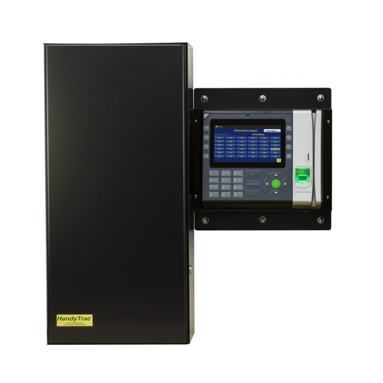
HandyTrac Touch Original operating instructions

HandyTrac Touch
Key Control System
SystemSystem
InstallationInstallation
&&
OperationOperation
GuideGuide
© HandyTrac Systems. All Rights Reserved.Handytrac.com service@handytrac.com
HARDWARE INSTALLATION
New System Setup...........................................................
Customer Supplied Hardware....................................
Cabinet Mounting & Alignment ...............................
Mounting System ............................................................
Double Cabinet Setup ..................................................
Key Panels ..........................................................................
POWER AND NETWORK SET UP
System Power ...................................................................
Establishing Communications ..................................
Connecting Using Wireless Connection ..............
INITIAL SETUP
Website Access ..............................................................
The Key Map ....................................................................
Adding & Removing Badges ....................................
Programming Fingerprints .......................................
SYSTEM USAGE
Pulling a Key .....................................................................
Returning a Key ..............................................................
Changing Apt/Unit# ....................................................
Editing Key Tags .............................................................
Website Features ...........................................................
Vendor Key Receipts ...................................................
12
13
14
15
18
20
24
25
27
33
8
9
10
2
3
4
5
6
7

HandyTrac Touch
User Guide
2
New System Setup
Congratulations on the purchase of your new
HandyTrac Touch Key Control System! This guide includes
installation and usage information for both the HandyTrac
Touch Premium and HandyTrac Touch Standard Key Control
systems.
If you have any questions regarding this process, please
contact a HandyTrac technician at 888-458-9994 or email
service@handytrac.com.
Your system includes:
Touch system (Premium pictured) Panels with assigned Keytags Cabinet(s)
Setup package includes: 1) Key Map 2) Spare Keytags
3) Master Badge 4) Installation and Operation Guide
Backup Cabinet Keys
(Taped to back of
cabinet)

HandyTrac Touch
User Guide
3
Customer Supplied Hardware
Tools Needed
Internet Connection
1. Uninterruptible Power Supply (UPS)
- Minimum rating of 450VA. Required as part system warranty. Provides surge
protection and backup battery power.
2. Mounting fasteners
- Minimum 50 lbs load capacity for masonry, drywall, wood or metal studs.
1. Drill & Drill bits
2. Level
3. Flat head screwdriver
4. Phillips head screwdriver
5. Pliers
Available Options
1. WiFi 2.4 GHz (WPA/WPA2, WEP, 802.1x EAP)
(5 GHz networks are not supported)
OR
2. Wired Ethernet
(CAT5e ethernet cable not included)

HandyTrac Touch
User Guide
4
1. Mount the cabinet on the wall.
2. Mount the HandyTrac Touch system keypad on the
wall beside the cabinet.
3. Install second cabinet (if applicable)
4. Insert key panels in the cabinet(s).
• Use metal or plastic for shimming. Wood and rubber do not hold their shape well.
• If the door gap at top is greater than bottom, shim the top of the cabinet at right hand
corner.
• If the door gap on the bottom is greater than the gap on the top, shim the bottom of
the cabinet at the right hand corner.
Cabinet Alignment
Do not place the
manual backup keys
inside the cabinet.
Check the gap between door and door frame on all sides. If the gap is not uniform all
the way around, the cabinet will have to be shimmed to compensate for the uneven wall
surface.
Familiarize yourself with these steps before you get started.
The basic installation order is as follows:
1. To achieve the recommended height, stack the system
shipping box on top of the key cabinet shipping box.
This will give you a platform 44” high.
2. Place the cabinet on top of the boxes, then place a
level on top of the cabinet.
3. We strongly recommend attaching the cabinet to a
stud. Align at least one (1) stud with one of the six (6)
drilled mounting holes at the top of the cabinet.
4. Use a pencil to mark your holes. A minimum of nine
(9) screws are required for mounting the cabinet to
ensure proper plumb, squareness, and stiffness.
5. When all holes are marked, use screws that penetrate
at least two (2) inches into the stud or wall that are
capable of holding at least 50 lbs. Follow the
manufacturer’s directions for all anchors.
6. Lift the cabinet into place and tighten all fasteners
snug, but not fully. Place your level on top of the
cabinet and check repeatedly as you tighten all of the
fasteners.
Mount the Cabinet
Minimum
9 screws
required

HandyTrac Touch
User Guide
5
Mount the HandyTrac Touch
1. Hold the Touch keypad ush against the
side of the cabinet. The Electronic Lock
port on the side of the cabinet must be
aligned with the electronic lock cables from
the keypad.
2. Before mounting the keypad, gently feed
the electronic lock cables through the
electronic lock cable port on the right
side of the key cabinet. Make sure all three
cables are in good condition. Fasten the
keypad to the wall with your mounting
hardware.
3. Connect the electronic lock, light, and
switch connectors inside the key cabinet.
The ends of each connector are labeled.
4. Push extra cable lengths inside the main
Touch console and snap the cables into the
retaining clips on the inside of the cabinet.
This prevents contact with the key panels
during operation and protects the cables.
*wire colors may vary

HandyTrac Touch
User Guide
6
Installation of Second Cabinet (if applicable)
Install the included spacer on the outside of the Right-Hand cabinet (marked RH).
Mount the second cabinet the same as the rst and feed the cables from the control box
through the spacer. Connect the wiring the same as the rst cabinet and clip down wires.
HandyTrac recommends a “left-to-right” hardware mounting process.
Insert the spacer through outside wiring hole. Thread on the included nut on the inside
to secure in place.
Opens to Left
(LH)
Opens to Right
(RH)
This will allow enough space for employees to comfortably scan keytags and also provide
protection for the electronic lock and light wiring.

HandyTrac Touch
User Guide
7
Multiple Cabinet Key Panels
1. The panels that belong in each cabinet will be shipped in separate boxes according to
the cabinet in which they need to be installed.
2. Larger systems (over 800 hooks) will contain additional labeling on the packaging to
indicate which panels belong with each touchpad.
3. If you are unsure which panels belong in which cabinet, please contact HandyTrac
Support at 888-458-9994.
AI
AI
Insert the Key Panels
The panels should be placed in alphabetical order from front to back in the cabinet
(AB/CD/EF/GH). Insert the top panel mounting pin in to a hole on the top key panel
mounting bracket. Lift the panel up and pivot the bottom mounting pin into the
corresponding hole in the bottom bracket. Do not remove the tags from the hooks.

HandyTrac Touch
User Guide
8
1. Plug the HandyTrac Touch power cable
into a UPS Battery Backup. Be sure the
HandyTrac Touch System is connected to a
plug that includes both Battery Backup and
Surge Protection.
2. Turn the system on using the power switch
on the bottom-right of the Touch system.
3. If your system does not power on, check to
make sure the battery is connected in your
UPS battery backup and that it is powered
on. Follow the manufacturer’s installation
and safety instructions for your UPS battery
backup.
System Power
NOTE: Your warranty will
be voided if a UPS battery
backup is not installed.
Power Switch
UPS Battery Backup
(Customer Supplied)

HandyTrac Touch
User Guide
9
Establishing Communications
1. An ethernet network cable can be connected
to the ethernet network port located at the
bottom-left of the system near the power
cord. An ethernet cable does not need to
be connected if you will be using a WiFi
connection.
2. Once powered on, the system will display the
main HandyTrac Touch system Time and Date
screen. (pictured below)
3. If the wired connection is not active, you will
receive a “No Network” popup notication.
You may need to contact your network
administrator if devices require approval.
4. You can test your connection by tapping the
HandyTrac logo on the display one time.
5. You should receive a notication that says
“Data Transfer was Successful.”
Ethernet Network Port
Note: Tapping on
“About” in the top
right corner will list
network connection
information.
The HandyTrac Touch system supports both wired and WiFi network connections.
Only one connection type is needed for communication.
Option 1: Wired Connection
*Advanced network options are
detailed on page 34

HandyTrac Touch
User Guide
10
Option 2: Wireless Network
1. If you have the “No Network” popup
on the display, tap on “OK” to dismiss
it to display the Time and Date screen.
2. Once the system is at the main Time
and Date screen, sign in by scanning
the Master Badge through the barcode
reader on the right side of the system,
then type in the PIN using the on-
screen keyboard.
3. Make sure that the bar code is facing
to the left when scanning the Master
Badge through the barcode reader.
The Master Badge PIN is listed
on the inside ap of the small
envelope containing the Master
Badge.
If you cannot locate the Master Badge, or if you have any issues logging in with the
Master Badge, please call Technical Support for assistance at 1-888-458-9994.

HandyTrac Touch
User Guide
11
4. Tap “Administration” in the top right-
hand corner of the touch screen.
5. Tap the “System Settings” icon.
6. Select “Wi-Fi” from the settings list.
(make sure Wi-Fi is toggled on)
7. Select your network and enter your
password when prompted. Passwords
are case-sensitive.
8. The status will change to “Connected”
when successful. “Saved” or
“Authentication Problem” are errors.
Note: Long pressing on the network
name will give you additional options to
“Forget” or “Modify” if you need to edit
the network password.

HandyTrac Touch
User Guide
12
1. Visit HandyTrac.com and click Sign In
at the top right corner to access your
HandyTrac account.
2. The “New Manager?” link on the Sign
In page allows you to email us the
necessary information for your new
account setup.
3. If you were previously set up with access
but you do not know your password, use
the “Forgot Password?” link.
4. If required, Email service@handytrac.com
or call 888-458-9994 and select Tech
Support from the menu to speak with
a HandyTrac Technician. A technician
can create your account and answer any
questions you may have about the new
system setup process.
Website Access and Setup Checklist
System Test Checklist
To test, log in to the HandyTrac keypad and
request a key out using the Master Badge.
(pg. 18 - Pulling a Key)
✔
Barcode Scanner reads badges
✔
Correct units are listed
✔
Door opens automatically when a
unit is requested
✔
The keytag you are directed to is
the correct keytag
✔
Transaction data is updated on the
website
Overview of Next Steps
1. Conrm all checklist steps
2. Match up keytags and keys
according to the key map
3. Add employees on the website
4. Add ngerprints (premium)
5. Congure Keys Out Emails
6. Congure Website Alerts
7. Train staff on pulling and returning
keys

HandyTrac Touch
User Guide
13
Matching Up Keys Using the Key Map
A printed key map is included with a new system in the setup packet.
Each keypad will have it’s own key map.
The key map must be used to match keys to tags as unit and tag locations are random.
The key panels will ship pre-populated with key tags on the indicated hooks.
Once keys are matched to tags, shred the printed key map. Not only is it a security risk,
the key map will no longer accurately reect your key locations once the system is in use.
The key map is constantly changing as you use the system but it is always available on the
website to authorized users. The key map should only be used in emergency situations
where you cannot use the HandyTrac system, such as complete power loss.
The key map depicted on this page is provided only as an example. Your key map will differ.

HandyTrac Touch
User Guide
14
Adding an Employee Badge
Editing or Removing an
Employee Badge
1. On the website, under “Administration” at
the top right, click on “Add/Edit Employee
Badges” in the Actions panel.
2. Click on the blue Add Employee button.
3. Fill out the elds including name, the six-digit
badge number, and create a four-digit PIN.
4. Choose an access level for the employee.
Most staff will only need Employee Access to
pull keys, but managers and administrators
should have Master Access. Master Access
allows editing units, tags, and ngerprints.
5. Choose a language that is displayed to the
employee when they sign in to the HandyTrac
keypad. Once done, save the new employee.
6. Once all your employees are added on the
website, go to the HandyTrac system keypad
and tap on the yellow HandyTrac Logo one
time. This will force a communication and
update the system with all current employees.
(page 9)
1. To edit an employee badge, click “Edit” at the end of the line for the employee from the
Active Employees list.
2. You can edit the Active status, badge number, PIN, access level, or language. You cannot
change the name associated with a badge.
3. To remove an employee badge from the system, simply change the “Active” eld to “No”
and save. This will remove that employee’s access and free up the badge to be re-added
with a new employee.
Note: It is critical that all
employees using the HandyTrac
system have their own badge and
PIN. If badges and PINs are shared,
the audit trail will not be valid.

HandyTrac Touch
User Guide
15
1. Make sure the employee is in the Active
Employees list on the website.
2. Before logging in to the HandyTrac
system, tap on the HandyTrac Logo on
the screen one time. This will force a
communication and update the system
with all current employees.
3. You should receive a notication that
says “Data Transfer was Successful.”
Adding Fingerprints for Employees
(Touch Premium system only. Master Access is required. Firmware v2.20+ is depicted in this guide.)
Employees must be added on the website rst. Once they are added to your
Active Employees list, you can add their ngerprint to their prole.
4. Tap on the word “Administration” in the
top right corner of the screen.
5. Tap “Fingerprint Setup” from the
Administration menu.
7. Select the employee whose ngerprint
you want to set up from the list.
8. Once the appropriate employee is
selected, tap on Register ngerprint.

HandyTrac Touch
User Guide
16
9. Make sure the protective lm is removed
from the ngerprint reader.
11. The system will chime and notify of
a successful read and display the
ngerprint image.
12. Repeat until the system says the print is
successfully registered.
10. Place your nger on the reader.
Notes:
• It is recommend you test your ngerprint access by logging out of the HandyTrac
system and signing back in by placing your nger on the reader.
• Badges and PINs can still be used in the event a nger is cut or no longer reads properly.
• Fingerprints are removed when an employee is deactivated on the website.
• The ngerprint preview should display a well dened and even print.
• If you have shallow ngerprints, it is recommended you use a larger nger on a non-
dominant hand.

HandyTrac Touch
User Guide
17
Using the HandyTrac Touch System
The HandyTrac Touch system must be at the default Time and Date screen for an
employee to gain access.
Use the biometric ngerprint reader OR scan your badge and type in your PIN.
You must be signed in to the system to pull or return any key. Fingerprint access is only
available on the HandyTrac Touch Premium.
Firmware v2.20+ is depicted in this guide.
HandyTrac Touch Premium HandyTrac Touch Standard

HandyTrac Touch
User Guide
18
Pulling a Key
1. Tap the “Pull Key” icon 2. Tap an Activity Code. Choosing an
appropriate Activity makes your audit
trail more accurate.
3. Tap the unit from the list. You can use
the Search box to nd units or, if you
have buildings programmed, you can
lter with the “All buildings” drop-down.
4. The system will electronically pop open
the door and tell you where to nd the
unit key you requested. Scan the key out
to verify it is the correct tag.
5. If you need multiple keys, continue to
select units from the list.
6. Once you are nished pulling keys, close
the cabinet door and tap Log Out.

HandyTrac Touch
User Guide
19
If the Apartment/Unit# you are looking
for is “grayed-out”, it has already been
requested out or it is restricted. Tapping the
unit will provide additional information.
Pulling a Key: Notes
If you are requesting multiple keys for
different purposes, you can change the
activity code by tapping the current activity
code at the top.
If you scan a keytag that is not assigned to
a unit, it will be rejected. Do not place the
keytag back in the cabinet as it does not
belong in the system.
Close the door before logging out of the
system. The cabinet door will only open one
time per session. You will be automatically
timed out after 60 seconds with no action.
These security measures prevent employees
from taking action under the login of a
different employee.

HandyTrac Touch
User Guide
20
Returning a Key
1. Log in to the HandyTrac system.
2. Tap on Return Key.
3. Scan the keytag.
4. Place the keytag on the hook the system
assigns. Scan all keys in one after the
other.
5. Close the cabinet door(s).
6. Log Out of the system.
Key Rotation
When a key is returned to the system, it will be assigned to a random empty hook. Because
of key rotation, printed key maps become inaccurate and should not be referenced once
the system is used. This is a security measure to prevent memorization of key locations.
The Key Map on the website is always updated with the new key locations and it is available
at any time to authorized users once logged in.
Occupied Hooks
When a key is scanned in to the system it will be assigned to a random empty hook. If there
is already a key on the hook, then that key is on the wrong hook.
Do the following to correct this error:
1. Remove the key that is on the hook.
2. Place the originally scanned key on the hook.
3. Scan in the incorrectly placed key as if it were a normal key return.
4. Place on assigned hook.
5. Repeat until all keys are returned to empty hooks if necessary.
Table of contents
Other HandyTrac Control System manuals
Popular Control System manuals by other brands

White Rodgers
White Rodgers 50M56U-801 installation instructions
Opencockpits
Opencockpits B737 manual
PLC Electronic Solutions
PLC Electronic Solutions HEDEN YMER 3 Operator's guide
BlueCarve
BlueCarve Turbo Setup
BACA SYSTEMS
BACA SYSTEMS EDGE XL Operation manual

Vibration Research
Vibration Research VR9500 quick start guide

Bryant
Bryant ZONE PERFECT PLUS ZONEBB2KIT installation instructions
Hydronix
Hydronix Hydro-Control HC07 installation guide

ELCOS
ELCOS CIM-130-KLRV Instruction and user's manual
heat-timer
heat-timer SQ-Elite-8S Installation and operation instruction manual

Vaillant
Vaillant VR 91 Operating and installation instructions

Dualsky
Dualsky FC450 instruction manual
