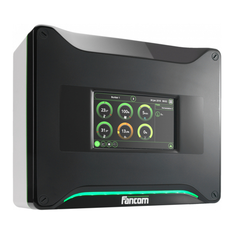
Fancom LUMINA 38 User manual

g

N.B.: The original, authentic version of this manual is the English version produced by Fancom B.V. or one of its
daughter companies (referred to further as Fancom). Any modifications introduced to this manual by third parties
have neither been checked nor approved by Fancom. Modifications are taken by Fancom to include translations
into languages other than English and the insertion and/or deletion of text and/or illustrations to/from the original
contents. Fancom cannot be held liable for any damages, injury, guarantee claims and other claims relating to this
type of modification, in as far as these modifications result in a content that differs from the original English
version of this manual produced by Fancom. For the latest information about product installation and operation,
please contact the customer service dept. and/or the technical service dept. of the Fancom concerned. In spite of
the care taken when compiling this manual, if you should discover any errors, please inform Fancom B.V. in
writing. Fancom B.V., PO Box 7131, 5980 AC Panningen (the Netherlands).
Copyright © 2020 Fancom B.V.
Panningen (the Netherlands)
All rights reserved. Nothing from this manual may be copied, distributed or translated into other languages, partly
or wholly, without express prior written permission from Fancom. Fancom reserves the right to modify this manual
without notice. Fancom can give no guarantee, neither implicit nor explicit, for this manual. All risks are for the
user.
This manual has been compiled with the utmost care. If, however, you should discover an error, please inform
Fancom B.V.
Art.Nr. 5911532
GB200330

Lumina 38
Table of contents
i
1. General introduction .................................................................................................................................. 1
1.1 Documentation with the control computer....................................................................................... 1
1.2 How to use this manual .................................................................................................................. 1
1.3 Fancom Sales & Service Center..................................................................................................... 2
1.4 F-Central FarmManager™.............................................................................................................. 2
2. Explanation control functions................................................................................................................... 3
2.1Ventilation....................................................................................................................................... 3
2.2 Heating......................................................................................................................................... 12
2.3 Cooling ......................................................................................................................................... 14
2.4 Humidifying................................................................................................................................... 15
2.5 HumiTemp.................................................................................................................................... 16
2.6 Optisec ......................................................................................................................................... 17
2.7 ImagO........................................................................................................................................... 17
3. Installing the Lumina 38........................................................................................................................... 18
3.1 Determine location........................................................................................................................ 18
3.2 Mount the Lumina 38.................................................................................................................... 18
3.3 Connect the Lumina 38 ................................................................................................................ 19
3.4 Installing the control computer...................................................................................................... 20
4. System....................................................................................................................................................... 21
4.1 System.......................................................................................................................................... 21
4.2 SD Card Menu.............................................................................................................................. 23
4.3 Application.................................................................................................................................... 24
4.4 Communication............................................................................................................................. 25
4.5 IO Test.......................................................................................................................................... 27
5. House setup.............................................................................................................................................. 28
5.1 House setup ................................................................................................................................. 28
6. Installer...................................................................................................................................................... 34
6.1 Ventilation..................................................................................................................................... 34
6.2 Heating, cooling and humidification.............................................................................................. 42
6.3 Clocks........................................................................................................................................... 44
6.4 Registration .................................................................................................................................. 47
6.5 Inside climate................................................................................................................................ 48
6.6 Outside climate............................................................................................................................. 49
7. External alarm........................................................................................................................................... 51
8. Basic principle thermo differential.......................................................................................................... 52
8.1 Operation...................................................................................................................................... 52
8.2 Assign thermo differential............................................................................................................. 52
8.3 Resetting the alarm ...................................................................................................................... 53
9. Inputs and outputs ................................................................................................................................... 54
9.1 Addresses..................................................................................................................................... 54
9.2 Calibration .................................................................................................................................... 54
9.3 Analog inputs................................................................................................................................ 54
9.4 Digital inputs................................................................................................................................. 55
9.5 Analog outputs.............................................................................................................................. 55
9.6 Digital outputs............................................................................................................................... 56
10. Technical specifications .......................................................................................................................... 57
10.1 Interior control computer............................................................................................................... 58
10.2 Power supply................................................................................................................................ 58
10.3 IOB.12 .......................................................................................................................................... 59
Lumina 38
Table of contents
ii
10.4 FRM.8........................................................................................................................................... 59
10.5 Connection FNet and I/O-net........................................................................................................ 60
11. Appendix: EC declaration of conformity ................................................................................................ 61

Lumina 38
General introduction
1
This manual has been created with the utmost care. If, however, you should discover an error, please inform
Fancom B.V..
The documentation consists of the following manuals:
•User's manual
The user's manual is intended for the end user. This manual supplies information about working with the
control computer after installation.
•Installer's manual
The installer's manual is intended for installers. This manual supplies information about connecting and
configuring the control computer.
•Operation and safety instructions
These subjects are covered in a separate manual. This manual also applies to other control computers in the
Fancom F2000-line. Always read the safety instructions and warnings carefully before using the control
computer.
Always keep this manual close to the Lumina 38.
The following symbols are used in this manual:
Tips and suggestions.
Note providing recommendations and additional information.
Warning indicating damage to the product if you do not follow procedures carefully.
Warning indicating danger to humans or animals.
Electric shock hazard. Danger to humans and animals.
Example of a practical application of the described functionality.
Calculation example.
Describes the key combinations for arriving at a particular screen.
Decimals
The control computer and this manual use a decimal point in values. For example: a weight is shown as 1.5 kg
(not as 1,5 kg).

Lumina 38
General introduction
2
For any questions and support, please contact the local Fancom Sales & Service Center.
Virtually all Fancom equipment can be controlled and managed from a central location. This requires the F-
Central FarmManager software package and a communication module. The screens in the control computers are
also used in F-Central FarmManager. This means you can start working immediately.

Lumina 38
Explanation control functions
3
Please refer to the user's manual for an explanation of the basic principles of climate management.
This chapter describes the working of a number of specific control functions that the installer should set.
Ventilation is used to create the most pleasant climate possible in the house. Ventilation also extracts harmful
substances from the house and introduces fresh air into the house. There are two types of house ventilation.
With mechanical ventilation, fans introduce air into the house and extract air. This means that you are less
dependent on the outside conditions. Several more fans are generally used with mechanical ventilation. The fans
used with specific ventilation percentages are indicated in the combi-table page 5.
The ventilation is controlled based on the house temperature. The purpose is to control the temperature as close
as possible to a certain setpoint. Minimum ventilation is always required in the house for the supply of fresh air.
If the temperature in the house exceeds the entered setpoint, ventilation must increase. The more the house
temperature differs from the setpoint, the more the ventilation increases. The ventilation zone is the temperature
range within which the ventilation is increased from its minimum to its maximum position.
Below is an example of a ventilation graph.
Figure 1: Ventilation graph
In the combi-table enter which fans have to activate at the various ventilation percentages.
The setpoint house temperature and the minimum and maximum ventilation positions can vary during the animals'
life cycle. The ventilation graph changes too and therewith the amount of ventilation at a certain temperature.
Always complete the combi-table.

Lumina 38
Explanation control functions
4
The control computer supports four types of house ventilation:
•Cross: With side ventilation the house is ventilated on the side. One side is the air inlet, the other side the air
outlet. The air flows across the house sideways. The inlet can be a minimum air inlet system or a natural
curtain. The outlet is mechanical (fan).
•Stair: With cross ventilation the house is ventilated from both sides. However, in this case the house is
divided into various sections in which ventilation comes from opposite directions.
•Ridge: With ridge ventilation the air enters the house from both sides and is exhausted via ridge ventilation.
•Length: With length ventilation the air enters the house from both sides and is exhausted via end wall
ventilation.
The control computer can control controllable fans and extra fans.
Controllable fans can be controlled by the control computer at a certain percentage. The control computer
controls the fans from, for example, 30% to 100%. This enables the control computer to increase ventilation
precisely up to the required level.
Figure 2: Example of a controllable fan controlled by the control computer
Controllable fans can be controlled by the control computer via the I/O-net or via an analog output (0–10V).
As well as the standard controllable fans, up to maximum three extra controllable fans can be controlled. The
extra controllable fans can be controlled directly (via an analog output or the I/O-net, value ‘A’ in the combi-table)
or via a relay (value ‘R’ in the combi-table).

Lumina 38
Explanation control functions
5
All controllable fans are always controlled at the same percentage.
Figure 3: Example of a controllable fan with one extra controllable fan. Directly controlled by the (A) or by the
relay (R)
Extra fans can only be switched on or off via a relay. They are usually used when the controllable fans are
running at maximum or in combination with controllable fans to achieve a gradual increase in ventilation.
Figure 4: Example of an extra fan switched on and off from the control computer by a relay

Lumina 38
Explanation control functions
6
The control computer determines the use of air inlets, extra inlets and fans based on the combi-table. Below is an
example of a combi-table. This may differ to your own combi-table, for example, because you use a different
number of extra fans. The combi-table shows the required values at successive positions (M1 thru M10 in the
example). The relay fans will do 20.000 m3 each and the controllable part is 25.000 m3.
M/MT-
phase
Exhaust
Inlets
Ctrl.
Mod.
Control-
lable/Extra
Relays
Inlet
(%)
Tun
(%)
Press
. (Pa)
Cap.
(m3/h)
(%)
1
2
3
1
2
3
4
5
6
7
8
9
10
M1
1
1
0
0
0
0
0
0
0
0
0
0
0
0
0
1
0
22
250
M2
20
100
0
0
0
0
0
0
0
0
0
0
0
0
0
20
0
20
25000
M3
21
25
0
0
0
1
0
0
0
0
0
0
0
0
0
21
0
20
26250
M4
36
100
0
0
0
1
0
0
0
0
0
0
0
0
0
36
0
20
45000
M5
37
25
0
0
0
1
1
0
0
0
0
0
0
0
0
37
0
18
46250
M6
52
100
0
0
0
1
1
0
0
0
0
0
0
0
0
52
0
18
65000
M7
68
100
0
0
0
1
1
1
0
0
0
0
0
0
0
60
10
16
85000
M8
84
100
0
0
0
1
1
1
1
0
0
0
0
0
0
80
10
14
105000
M9
100
100
0
0
0
1
1
1
1
1
0
0
0
0
0
100
15
14
125000
M10
0
0
0
0
0
0
0
0
0
0
0
0
0
0
0
0
0
0
0
The combi-table also contains the ventilation capacity. This is used to determine the ventilation position if control
is based on ventilation capacity per hour per animal (m3/h/animal).
The required pressure in the combi-table is used to control the inlet based on the under pressure in the house.
See Optimisation based on pressure page 9.
The ventilation level is expressed as a percentage. Using this percentage the control computer can locate the
required level of control of the fan(s) in the combi-table.
Extra fans are shown in the combi-table as value ‘0’ (off) or ‘1’ (on).
The combi-table is sub-divided into positions (M1 thru M10 in the example). If the ventilation level is between two
positions, the control computer determines the middle point of these positions. The following rules apply:
•Controllable fans: the control computer gradually controls the ventilation position from one position to another
and also adjusts the air inlets and extra inlets.
•Extra fans: with rising ventilation the control computer will only activate the fans when the next position has
been reached. With falling ventilation the control computer will only deactivate the fans when the lower
position has been reached.

Lumina 38
Explanation control functions
7
Example: Taking ventilation positions from the combi-table
The required ventilation level on a certain day is 21%.
The control computer uses the settings at position M3:
•Controllable fans and the extra controllable fans: 25% activated.
•Contr./Extra fans: deactivated.
•One Exhaust relay fan activated.
•Air inlets: 21% open.
•Tunnel inlets: Do not use.
Example: Settings between two positions
The required ventilation level is 28%. This percentage is between positions M3 and M4. The control
computer uses the following settings:
•Controllable fans and the extra controllable fans: 62% activated.
•Contr./Extra fans: deactivated.
•One Exhaust relay fan activated.
•Air inlets: 28% open (midway between M3 and M4).
•Tunnel inlets: Do not use.

Lumina 38
Explanation control functions
8
The settings that have to be made for the tunnel part (T-part) correspond broadly with the settings for the M/MT-
part. Instead of the ventilation position in % you enter the offset temperature for the positions. At the first position
this offset temperature is linked to start temperature ventilation + calculated bandwidth. Each following position is
linked to the previous position via an offset. In other words: the control computer never controls in between two
positions.
M/MT-
phase
Exhaust
Inlets
Ctrl.
Control-
lable/Extra
Relays
Inlet
(%)
Tun
(%)
Press
. (Pa)
Cap.
(m3/h)
ºC
1
2
3
1
2
3
4
5
6
7
8
9
10
T1
2.0
0
0
0
1
1
1
1
1
1
0
0
0
0
50
25
0
120000
T2
1.0
0
0
0
1
1
1
1
1
1
1
0
0
0
0
50
0
140000
T3
1.0
0
0
0
1
1
1
1
1
1
1
1
0
0
0
75
0
160000
T4
1.0
0
0
0
1
1
1
1
1
1
1
1
1
0
0
100
0
180000
T5
0
0
0
0
0
0
0
0
0
0
0
0
0
0
0
0
0
0
T6
0
0
0
0
0
0
0
0
0
0
0
0
0
0
0
0
0
0
T7
0
0
0
0
0
0
0
0
0
0
0
0
0
0
0
0
0
0
T8
0
0
0
0
0
0
0
0
0
0
0
0
0
0
0
0
0
0
T9
0
0
0
0
0
0
0
0
0
0
0
0
0
0
0
0
0
0
T10
0
0
0
0
0
0
0
0
0
0
0
0
0
0
0
0
0
0
Modulating control can be used to control the ventilation level in percentages of a cycle time. The control
computer activates/deactivates the fans according to a fixed pattern. This supplies fresh air in short repeated
periods. Modulating fans are shown in the combi-table by the letter M.
Example: Modulating ventilation
The required ventilation position of the fans: 21%
The control computer will control the fans on for 50% of the set cycle time. The ventilation is off for 50%
of the time.
Determining the ventilation position
The control computer determines the use of air inlets, extra inlets and fans based on the combi-table. The
example below shows a combi-table with modulating fans. The relay fans will do 20.000 m3 each.

Lumina 38
Explanation control functions
9
Ventilation
Exhaust
Inlets
Position
MOD
Extra fans
Relay (0-1-M)
Cap.
Inlet
Extra
Pres-
sure
%
%
1
2
3
4
5
m3/h
%
%
Pa
M1
1
1
M
0
0
0
0
200
1
0
0
M2
20
100
M
0
0
0
0
20000
20
0
0
M3
21
50
M
M
0
0
0
21000
21
0
0
M4
39
99
M
M
0
0
0
39000
39
0
0
M5
40
100
1
1
0
0
0
40000
40
0
0
M6
60
100
1
1
1
0
0
60000
50
0
0
M7
75
100
1
1
1
1
0
80000
75
0
0
M8
100
100
1
1
1
1
1
100000
100
0
0
The ventilation level is expressed as a percentage. The control computer uses this percentage to find the required
ventilation settings in the combi-table. The control computer determines the ventilation % between two positions,
and controls the modulating fans using this.
Example: Taking ventilation positions from the combi-table
Required ventilation level: 30%. This value is precisely between positions M3 and M4.
The control computer uses the following fans:
•Both fans are controlled on for 75% of the set cycle time (midway between M3 and M4). If the
ventilation level increases further, so will the modulation percentage.
•Air inlet control depends on the settings. The control computer can open the air inlets 30% (midway
between positions M3 and M4). The inlet position can also be modulated between 21% and 39%.
The control computer controls ventilation with fans (exhaust) and air inlets. The control computer takes the
positions from the combi-table. The combination of exhaust and inlet positions creates a certain under pressure in
the house. The required under pressure is in the combi-table. The control computer can influence position of the
air inlets and accurately control the pressure. (Optimisation).
The control computer can control the fans modulatingly. Modulating means that a control (linear or relay) is
activated only during a part of the total cycle time. Modulating control allows minimum ventilation to be achieved
using, for example, a large fan.
Fancom differentiates between the following types of modulating control:
•Modulating control with fixed modulation times
•Modulating control with optimised modulation times
•Modulating control with MicroControl®
•Rotating modulation
These types are explained in the next sections. This explanation is also relevant for linear controlled fans.

Lumina 38
Explanation control functions
10
Linear controlled fans have a minimum ventilation level, for example 30%. This determines below what
percentage the ventilation will modulate, and the ventilation level during modulating. If, for example, the calculated
output of the linear part is 10%, ventilation will run for 10/30th of the cycle time at 30%, and not run for the rest of
the time.
With this type of control enter the fixed cycle time (ON- plus OFF-time). The total cycle is as follows:
Example modulating control with fixed ON-time
Cycle time: 10 minutes
Modulate below %: 30%
Control value ventilation: 15%
If the control value ventilation is lower than 30%, the control computer will use modulating ventilation.
The controllable part will be active for half of the cycle time of 10 minutes, with a ventilation level of
30%. This means an ON-time of 5 minutes and an OFF-time of 5 minutes. The control computer always
controls based on these times.
With optimal modulating control the control computer aims for an optimal ON-time and an optimal OFF-time
entered by the installer. The examples below shows that the switch off moment and cycle time can vary:
Example - Optimum modulating control (1)
Optimum ON-time: 2 minutes
Maximum cycle time: 10 minutes
Modulate below %: 30%
Control value ventilation: 15%
If the control value ventilation is lower than 30%, the control computer will use modulating ventilation.
The control computer assumes an optimum ON-time of 2 minutes and a ventilation level of 30%. This
means that the optimum ON-time of 2 minutes must be half of the total cycle time. The control computer
calculates a cycle time of 2 x 2 = 4 minutes (2 minutes on and 2 minutes off). In this example the OFF-
time will also be 2 minutes.
Example - Optimum modulating control (2)
Optimum ON-time: 2 minutes
Maximum cycle time: 10 minutes
Modulate below %: 30%
Control value ventilation: 3%
The control computer assumes an optimum ON-time of 2 minutes. This means that the optimum ON-
time of 2 minutes must be a tenth (=3/30) of the total cycle time. The control computer calculates a
cycle time of 10 x 2 minutes = 20 minutes (2 minutes on and 18 minutes off). However, this is longer
than the maximum cycle time of 10 minutes.
The control computer will calculate new ON- and OFF-times based on the maximum cycle time as
follows: 1/10 of 10 minutes means an ON-time of 1 minute. The rest of the time the control remains
switched off.

Lumina 38
Explanation control functions
11
In order to ventilate the right amount of air and to have a perfect air distribution, it is possible to ‘pulse’ the air to
the middle of the house for a fixed amount of time and then wait until the fresh air is nicely spread over the birds.
This way of ‘pulsing’ is known as MicroControl®.
The ventilation cycle always starts with a Minimum ON time. During the first phase of minimum ventilation this
time is always fixed to ensure that the air reaches the middle of the house. Typically, this value is 40-60 seconds.
The right setting can be determined by executing a smoke test.
Subsequently, the fans stay off for a certain time while the inlets are closed. During this time the air will be nicely
distributed over the birds. This OFF time is automatically calculated.
To ensure the refresh rate (number of ventilation cycles per hour) a Maximum cycle time can be set. A setting of
10 minutes means that the total ventilation cycle will run at least 6 times per hour. MicroControl® can also be
used in combination with variable speed fans of I-Fans. The setting Modulating below % is used to make the
setting where the controller switches from variable speed control towards modulating control and vice versa.
Example - On/off fans
Minimum ON time: 45 seconds
Maximum cycle time: 10 minutes
Control value fan: 10%
The control computer uses a minimum ON time of 45 seconds. This means that the minimum ON time of
45 seconds must be 10% (control value fan) of the total cycle time. The control computer calculates an
OFF time of 9 x 45 seconds = 405 seconds (45 seconds ON and 405 seconds OFF). In this example the
calculated cycle time will be 450 seconds.
Example - Variable speed fans
Minimum ON time: 45 seconds
Maximum cycle time: 10 minutes
Modulate below %: 30%
Control value fan: 10%
If the control value ventilation is lower than 30%, the control computer will use modulating ventilation.
The control computer uses a minimum ON time of 45 seconds and a fan control level of 30%. This
means that the minimum ON time of 45 seconds must be 1/3 (10/30) of the total cycle time. The control
computer calculates an OFF time of 2 x 45 seconds = 90 seconds (45 seconds ON and 90 seconds
OFF). In this example the calculated cycle time will be 135 seconds.

Lumina 38
Explanation control functions
12
The fans which must activate at a certain ventilation position have been set in the relay or combi-table. However,
this means that the same fans will always be active. Using rotating the control computer will activate the number
of assigned fans, but in a different sequence each time. This creates an optimal spread of air in the house. In
addition, all fans are evenly used.
Rotating the sequence is impossible if all combi-relays (assigned for rotation) are activated.
The control computer has various heating controls that can be assigned independently.
Temperature zones in the house
A heater (blower) often only warms part of the house. It is better to divide the house into zones, and link certain
temperature sensors to the heater for this zone.
Separate setpoint heating
Usually one setpoint house temperature is used for ventilation and heating. The heating can also be given a
separate setpoint, the so-called ‘extra temperature’. The extra temperature must be entered in the curve.
This may be necessary if floor heating is controlled based on temperature. In this case, the sensor measures a
different temperature to the actual house temperature.
High/low-control heating
Heaters can be linked together. Heater 1 is always the basis. For example, if heater 2 is linked to heater 1, these
heaters will always use the same actual setpoint. If the control value of heater 1 is changed, the control value of
heater 2 will change accordingly.
The above can also be used for low/high control. The control computer will activate the heaters one by one:
•With a small difference between the control value of heater 1 and the house temperature, the control
computer will activate this heater.
•As it gets colder, the difference increases. The control computer then activates extra heaters.
Enter to which analog inputs the temperature sensor(s) have been connected and to which outputs the heating
controls have been assigned. Also enter the type of control: RELAY or ANALOG. The type of control depends on
the heating system used. There are two relay controls (On/Off and modulating).
The controls used to control the heating are explained below.

Lumina 38
Explanation control functions
13
The control computer activates heating if the house
temperature drops below Setpoint –hysteresis. If the
house temperature rises, the heating will stay on until the
control value heating is reached.
A set Repeat time can be used to prevent unnecessary
activation/deactivation of the heating. When the heating
activates, it will remain on for at least the Repeat time.
When the heating deactivates, it will remain off for a
minimum of this time.
The heating is continuously on, if the temperature of the heating control is lower than Setpoint –hysteresis.
The heating is continuously off, if the temperature is equal to or higher than the Setpoint.
Heating is modulating on, if the temperature is in the Hysteresis. The control computer calculates the modulation
time based on the Repeat time.
Example: Time modulating heating control
Inside Hysteresis the control computer controls heating during a part of the Repeat time. The control
computer calculates this on/off time as follows:
•Setpoint: 20.0 °C
•Measured house temperature: 19.6 °C
•Hysteresis: 1.0 °C
•Repeat time: 100 sec.
The heating relay will repeatedly be on for 40 seconds and off for 60 seconds.

Lumina 38
Explanation control functions
14
With analog heating control the heating is controlled by a P- or PI-control. Use Repeat time to determine the type
of heating control. If the Repeat time is less than 10 seconds, a P-band control is concerned. In other cases PI-
control applies.
P-control
If the temperature is higher than the Control value,
heating is on the minimum position. The minimum
position is a user setting.
If the temperature is between the Control value and
Control value P-band, heating will be at a position
between minimum and 100%, depending on the
difference.
As long as the measured house temperature is lower
than Control value - P-band the control computer will
output the maximum control signal.
The P-band is a user setting.
PI control
If the temperature is lower than the Control value, the control computer will control the heating directly based on
the temperature difference. As long as the temperature is too low, the heating will go to an increasingly higher
position (max. 100%). The increase/decrease speed depends on the time set by the user (usually between 100
and 600 seconds).
The control computer can be used to control a cooling unit. Enter to which analog inputs the temperature
sensor(s) have been connected and to which relay the cooling has been assigned. Also enter the type of relay
control: ON/OFF or MODULATING. The type of control depends on the chosen cooling system.
With evaporative cooling you can use the Max. RH limit with evaporative cooling. This influence is explained in
the user's manual.
The control computer can use a hysteresis. This prevents the cooling being activated or deactivated with slight
temperature fluctuations. The control computer activates the cooling if the house temperature rises above the
hysteresis. If the house temperature drops, the cooling will stay on until the house temperature has dropped
below the setpoint cooling. If a evaporative cooling is selected the control is explained in the user's manual.
The ON/OFF control and the time modulating ON/OFF control to control the cooling are explained here:
ON/OFF control
Cooling activates if the house temperature is higher than Setpoint
+ hysteresis.
Cooling deactivates if the temperature is equal to or lower than
Setpoint.
A Repeat time can be used to avoid unnecessary
activation/deactivation of the cooling. When the cooling activates,
it will remain on for at least the Repeat time. When the cooling
deactivates, it will remain off for a minimum of this time.

Lumina 38
Explanation control functions
15
Time modulating ON/OFF control
This type of control can be selected if the cooling capacity is large and the cooling system is suitable for
modulating control.
Cooling is continually on, if the temperature of the cooling control is higher than Setpoint + hysteresis.
Cooling is continually off, if the temperature is equal to or lower than the Setpoint.
Cooling is modulating on, if the temperature is in the Hysteresis. The control computer calculates the modulation
time based on the Repeat time.
Example: Time modulating cooling control
Inside Hysteresis the control computer controls the cooling for a part of the Repeat time. The control
computer calculates this on/off time as follows:
•Setpoint: 27.0°C
•Measured house temperature: 28.5°C
•Hysteresis: 3.0°C
•Repeat time: 100 sec.
The cooling relay will repeatedly be on for 50 seconds and off for 50 seconds.
The humidity control can only activate if a humidity setpoint has been set. Enter to which relay the humidity
control has been assigned. Also enter the type of relay control: ON/OFF or MODULATING.
See also Settings humidity page 43.
The control computer has two types of humidity control:
1. ON/OFF control
Humidifying activates as soon as humidity in the house drops
below Setpoint humidity –hysteresis.
Humidity deactivates when the measured house humidity is equal
to or higher than Setpoint humidity.
A Repeat time can be used to avoid unnecessary
activation/deactivation of the humidity. When the humidity
activates, it will remain on for at least the Repeat time. When the
humidity deactivates, it will remain off for a minimum of this time.
2. Time modulating ON/OFF control
The humidity is continually on, when the measured house humidity is lower than Setpoint –hysteresis.
The humidity is continually off, when the house humidity is equal to or higher than Setpoint.
Humidity is Modulating on, if the humidity is in the Hysteresis. The control computer calculates the
modulation time based on the Repeat time.

Lumina 38
Explanation control functions
16
Example: Time modulating humidity control
Inside Hysteresis the control computer controls humidity during a part of the Repeat time. The
control computer calculates this on/off time as follows:
•Setpoint: 80%
•Measured RH: 75%
•Hysteresis: 10%
•Repeat time: 100 sec.
The humidity relay will repeatedly be on for 50 seconds and off for 50 seconds.
HumiTemp = Humidification Temperature
If HumiTemp is used, it will correct the measured average house temperature depending on the setpoint and the
measured relative humidity (RH). If HumiTemp is not used, the ventilation is controlled based on the average
house temperature.
Figure 5: Example HumiTemp
The HumiTemp control can only activate if a humidity setpoint has been set and a humidity sensor is adjusted.
The effect of the HumiTemp correction is controlled by the next settings.
The age factor tells how the HumiTemp ® should adapt in relation to the age of animals. This means there is a
link to the minimum ventilation. EARLY (5%) means that even at young animals the HumiTemp will react
strongly. When this factor is NORMAL(10%) the reaction is a more gradually, and this impact is slowly with the
factor at LATE(20%).
At a lower than desired RH the temperature will run down. The degree of correction is limited (safety reason). This
setting specifies how much the compensation may decrease (related to the average house temperature) TINY (-
0.5 °), SMALL (-1.0 °), average (-1.5 °), LARGE ( -2.0 °) and HUGE (-2.5 °).
With a higher than desired RH the temperature will run up. The degree of correction is limited (safety reason).
This setting specifies how much the compensation may increase (related to the average house temperature )
TINY (1.0 °), SMALL (2.0 °), average (3.0 °), LARGE (4.0 °) and HUGE (5.0 °).
This manual suits for next models
1
Table of contents
Other Fancom Control System manuals

Fancom
Fancom 743 User guide

Fancom
Fancom MRK.2 User manual

Fancom
Fancom ITM-iF User manual

Fancom
Fancom INTELLITEK User manual

Fancom
Fancom FB.1 User manual

Fancom
Fancom VLR.6 User manual

Fancom
Fancom LUMINA 41 User manual

Fancom
Fancom 750 User manual

Fancom
Fancom LUMINA 71 User manual

Fancom
Fancom 743 User manual