Dualsky FC450 User manual

#21050
http://www.dualsky.comMade in China 21ZX13E1720
w
w.dualsk
y
.com
Shanghai Dualsky Models co.,Ltd.
Rm.1016,No.201,Xin Jin Qiao Rd.,Shanghai,China.
Tel: +86 21 50322162 Fax: +86 21 50322163
FC450四旋翼飞行控制器
使用说明书
FC450
FC450 Flight Control System
Instruciton Manual
(c)
(a)
(d)
(b)
21021-1
Double
Sided
Tape
Packing List
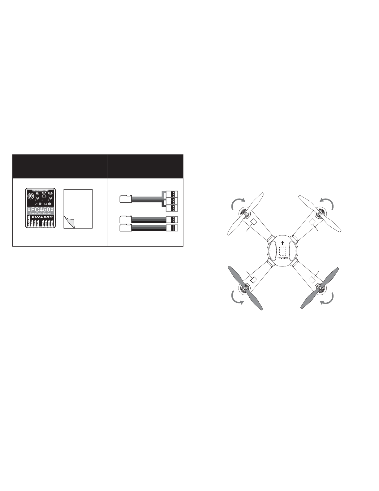
(a)
FC450 Flight control system x1
(b)
Shockproof double sided tape x1
(c)
3 in 1 signal wire x 1
(d)
Standard signal wire x 2
Install Instruction
1. Please follow the instruction manual from the frame and power
system manufacture to finish the installation of the frame and
power system. Please notice the install direction of the flight
control system and the running direction of the propellers, they
must be the same as the following diagram 1 or 2. (Please make
sure to use the double sided tape comes with FC450 to mount it
on frame.)
- 2 -- 1 -
Equipment Needed
Besides FC450, you need the following equipments to complete your
quadcopter: a 4-channel radio system (we recommend a 6-channel
or higher radio system), one set of quadcopter motor and ESC
(4 motors and 4 ESCs), propellers, one quadcopter frame, Lithium
Polymer (LiPo) battery pack and battery charger. Diagram 1 (X Type)
ESC1
ESC4
ESC2ESC3
Head Direction

(Orange)
(Red)
(Brown)
RATE
RUDD
A/ E/ T
CH5/GEAR
Rudder
Aileron
Elevator
Throttle
Reserved
AIL
ELE
THR
RUD
CH5
3. FC450 supports 4.8V-7.4V input voltage. Since it shares the same
input power with the receiver, the input voltage must also meet the
requirements of the receiver.
a) When use external power supply, please cut the ESC BEC
output like Diagram 4;
b) When use ESC BEC, please only use one BEC output, cut the
rest 3.
SBUS
+
-
+
-
+
-
Aileron Rudder RATE
Elevator
Throttle
Input
ESC4 ESC3 ESC2 ESC1
+
-
+
-
+
-
+
-
Output
Diagram 2 (Cross Type)
2.FC450 port diagram (Diagram 3)
Diagram 4
4.Connect FC450 to receiver as shown in Diagram 5
- 4 -- 3 -
Diagram 5 (Normal Receiver)
Head Direction
ESC1
ESC4
ESC2
ESC3
Diagram 3

S.BUS
Futaba JR Spektrum
AILERON
ELEVATOR
THROTTLE
RUDDER
NOR
REV
NOR
NOR
NOR NOR
NORREV
REV
REV
REV
REV
CH5/GEAR NOR REV NOR
HOTT
NOR
NOR
REV
REV
REV
1300μs
900μs
2100μs
Self-stabilizing Mode
Manual Mode
switch the flight mode.
If you are using a 4-channel radio controller, the flight mode can be
set in FC450.
●Set the radio to “Airplane Mode”, turn off all the mixing functions,
set all channel’s D/R to 100%;
●Set all channel’s trim, sub-trim and mechanical trim to “0”;
●Set all channel’s direction according to the below chart;
●Please check the Diagram 6 for corresponding value of channel
direction.
Configuration
●The FC450 needs a 4-channel or higher radio controller to operate;
If you are using a 5-channel or higher radio controller, please sign
a 3-position or 2-position switch on the radio to CH5/GEAR
channel and make sure the switch doesn’t have other function, set
this switch to Low (Switch channel pulse width range should be:
low 900~1300μs, high 1300~2100μs). This channel is used to
Ch1 Ch2 Ch3 Ch4 Ch5
Aileron Elevator Throttle Rudder Rate
S.BUS receiver channel mapping sequence chart:
Diagram 6
- 6 -- 5 -
Diagram 5 (S.BUS Receiver)
Channel
Sequence

ESC Initial Setting
Before install FC450, please finish the ESC initial setting. Make sure
ESCs and FC450 have the same stroke setting.If you use Dualsky ESC,
you can set all ESCs after FC450 installation by the following steps:
●Turn on the radio controller, push the throttle stick to the top, turn
on power to the quadcopter, when L1 shows blue in color, it means
the ESC is in initial setting mode;
●Wait until the ESC's long beep (it means the top point of throttle
has been confirmed), then pull the throttle stick to lowest point;
●Wait about 1 second for a short beep (it means the lowest point of
throttle has also been confirmed), the ESC initial setting is finished;
●Don't move the throttle stick after initial setting, turn the power off
to the quadcopter, then reconnect the power after 5 seconds, the
new setting will be applied.
- 8 -- 7 -
FC450 Setting
●How to enter Setting Mode: Turn on radio controller, move the
throttle to lowest position; turn on power to the quadcopter, wait
until the L1 LED finishes flashing Green and then changes to RED
(Now the flight control is in Lock Mode); press the “SET” button on
the flight control to enter Setting Mode. After you enter Setting
Mode, L1 displays the corresponding SETTING ITEM menu
attributes (color), and L2 displays the corresponding SETTING
VALUE menu attribute (color).
●“SET” Button usage:
1) Long Press (more than 2 sec) under Lock Mode: enter Setting
Mode
2) Single Click under Setting Mode: switch between SETTING ITEM
3) Double Click (finish within 0.5 sec) under Setting Mode: change
SETTING VALUE
4) Long Press (more than 2 sec) under Setting Mode: Save and
Quit to Lock Mode
●Please check the chart at the right side for all settings.
Some settings will take effect after the FC450 restarted. Cut the power to the
quadcopter and reconnect after 5 seconds to apply the new settings.
Flight Mode
ESC PWM Freq.
Aircraft mode
Factory Reset
Blue
Green
Red
Yellow
White
Potentiometer Lock
L1
Setting Item Setting Value
Blue Green
* Blue color setting
indicates default values
200Hz 266Hz 333Hz 400Hz
L2
Red Yellow
Self-stabilizing
Mode
Not Lock
X Type
Lock
Flashing
Recovery
Cross Type
Manual
Mode

Ground Test
●Set all sensitivity potentiometers on FC450 to neutral.
●CH5 is used to adjust flight mode, if you are using it, please toggle
the CH5 switch before flight, L2 LED will indicate the state of the
current switch position: blue indicates low stick input, green
indicates high stick input. Put the CH5 switch to low(auto level
flight mode).
Unlock & Propeller Direction Check
●Make sure your quadcopter's battery is fully charged, and you are
in a wide and flat area;
●Turn on the radio, pull the throttle stick to lowest position, plug in
the power to the quadcopter. L1 LED on FC450 Flight Control will
flash Green (initial startup process), don't move sticks on the radio
controller, keep the quadcopter still. When the L1 LED changes to
Red, it means the initial startup process has finished and the
quadcopter is now in Lock Mode (throttle will not operate). Move
the sticks as shown in the diagram 7 and hold for about 0.5 sec to
unlock the quadcopter. After unlock, motors will reach idle speed
for about 1 sec. If you don't do any stick movements during this
period after "unlock" (5-seconds) the quadcopter will return to Lock
Mode again.
- 9 - - 10 -
●After unlock, push the throttle a fraction above idle speed, check if
the propellers run in correct direction like shown in below diagram.
Diagram 7
L2
Blue (0.5S)
Low
L2
Green (0.5S)
High

- 12 -- 11 -
●Direction check: Controlling the throttle, make sure the quadcopter
doesn't leave the ground. Slightly move each stick to observe if the
quadcopter moves with your stick input direction. If the direction is
opposite, please change the channel direction on the radio.
Low altitude Test Flight
●After unlock, control throttle to make the quadcopter maintain a 0.5
meter altitude. Observe if the quadcopter is stable. If it’s not stable,
you need to adjust the sensitivity of the FC450.
●The channel center point can differ depending on the choice of
radio brand, the installation of FC450 can also cause deviation. If
the quadcopter has deviation after take off, please adjust the trim
on radio to find the center position.
Adjust the sensitivity
●450 class quadcopter can use the default setting to get a good
flight performance.
●The weight on the quadcopter can differ depending on the choice
of battery. This will impact center of gravity, and the flight
characteristics. To improve flight performance you can address the
below.
●Normally, if the sensitivity is set too high on the “pitch” (elevator)
axis, the opposing axis (i.e., aileron) will vibrate; if the sensitivity is
set too low on the “pitch” (elevator) axis, the opposing axis (i.e.,
aileron) will respond with delay to stick movement.
●If the sensitivity is set too high on the rudder axis it will cause the
motors to over react, which will make the quadcopter unstable in
pitch and yaw direction; if the sensitivity is set too low on the
rudder axis, the quadcopter will have difficulty on tail lock.
●When adjusting the sensitivity, don’t change the setting value too
much, 5-10 degrees a time is enough. When you find a stable
range, then tweak it for optimum performance.
Caution
●Please don’t pull throttle to the lowest position during flight, it might
cause the motor suddenly be stopped and crash the quadcopter.
●When you fly in high maneuvering condition for a long time, the
external acceleration will cause the FC450 cannot maintain a
horizontal status. It’s normal, hovering the quadcopter for few
seconds, FC450 will adjust the quadcopter to complete horizontal.

FC450四旋翼飞行控制器
使用说明书
FC450
上海双天模型有限公司
Tel: +86 21 50322162 Fax: +86 21 50322163
#21050 - 14 -- 13 -

- 16 -- 15 -
所需设备
除本产品外,为了安装您的四旋翼,您还需要以下设备:
一套四通道或以上遥控设备、一套四旋翼电机电调(四对)、
正反桨(两对)、四旋翼机架、动力锂电池及充电器。
物品清单
(a)FC450平衡仪×1
(b)减震双面胶×1
(c)三信号排线×1
(d)单信号排线×2
(c)
(a)
(d)
(b)
安装指南
1.机架与动力设备的安装请遵循机架与动力生产厂商的相
关说明。注意螺旋桨的旋转方向和FC450(请使用随包装
附送的减震双面胶固定)的方向必须如图1或图2所示。
21021-1
Double
Sided
Tape
双面胶
图 1 (X型)
头部方向
ESC1
ESC4
ESC2
ESC3

(Orange)橙色
(Red)红色
(Brown)棕色
RATE
RUDD
A/ E/ T
CH5/GEAR
Rudder
Aileron
Elevator
Throttle
Reserved
AIL
ELE
THR
RUD
CH5
- 18 -- 17 -
图 5 (普通接收机)
图 2 (+型)
2.FC450的接口如图3所示
图 3
图 4
3.FC450的供电方式, FC450支持4.8V-8.4V的电压输入,由
于和接收机共用电源,输入电压也要符合接收机的要求。
a)外部电源供电,此时应切断电调的BEC输出,如图4所示:
b)电调BEC供电,请使用单电调BEC供电,切断其他电调
的BEC输出 。
4.FC450与接收机连接图5所示
SBUS
+
-
+
-
+
-
Aileron
输入
Rudder RATE
Elevator
Throttle
ESC4 ESC3 ESC2 ESC1
+
-
+
-
+
-
+
-
输出
头部方向
ESC1
ESC4
ESC2
ESC3
Table of contents
Other Dualsky Control System manuals


