Hang ups Teeter Power V User manual

Patent applies.
ASSEMBLYINSTRUCTIONS
Power VTM
Note: The Bed Frame arrives rotated into the fully inverted position. This is the most
convenient position from which to begin the assembly process.
STEP ONE
Attach the Bed Frame (PV1001) on the A-Frame (PV1002)
• OpentheA-frameandmakesurethatthespreaderarmsarelockedflat.
• Lift the Bed Frame (the logo on the bed will be facing the rear) and place the
shroudsoverthetopoftheA-Framelegs.(See FigureA) WARNING: Bed
Frame weighs 50 lbs. If you are unsure of your ability to comfortably lift
this weight, please seek assistance in assembling this product.
• MakesureBedFramerests evenly ontheA-Frameandthat the holes arealigned.
Before you begin: These instructions will guide you in properly assembling the unit. Please review all the steps before beginning assembly.
Carefully adhere to the Assembly Instructions and Owner’s Manual to help ensure user safety and product integrity.
A-Frame
PV1002
Shroud
Main Shaft
PV1003
ASSEMBLY
DONOTDISCARD- KEEP FORFUTURE REFERENCE.
Wrench
PV1007
PV1005
arriveassembled
inthemainshaft
Locking Knobs
Figure A
• Insert and tighten the Screws (PV1006) into the shrouds on both sides of
the Bed Frame. (See Figure B)
• Tightenwiththe wrenchprovided.
Figure B
BedFrame
PV1001
ITEMSFORASSEMBLY ITEM #’s
Bed Frame PV1001
A-Frame PV1002
Main Shaft PV1003
Locking Knobs (2) PV1005
Screws (4) PV1006
Wrench PV1007
Handles (2) PV1008
Carefully remove the individual parts from the carton. You should have all of the items listed below. If any items are missing or damaged, contact
your retailer or customer service directly (See reverse side).
PRE-ASSEMBLY
1. It is your responsibility to familiarize yourself with the proper use of the equipment and the inherent risks of inversion, such as falling on your
head or neck, pinching, entrapment or equipment failure.
2. This product is not designed for persons over 6’6” (198 cm) or 300 lbs (136 kg). Structural failure could occur or head/neck may impact floor
during inversion. Serious injury or death could result.
3. DO NOT use the equipment without a licensed physician’s approval and a review of the medical contraindications, as noted in the Owner’s Manual.
4. Failure to assemble and/or use the equipment as directed may void the manufacturer’s warranty on this product and could result in injury or death.
5. DO NOT use the inversion table until you have thoroughly and carefully read the Owner’s Manual, reviewed all other accompanying
documents, and inspected the equipment.
6. This product requires a grounded outlet. Improper connection to a 3-prong grounded outlet can result in electrical shock.
7. Choose a level surface for assembling and operating the table.
8. Follow each step in sequence. Do not skip ahead.
9. Make sure that all fasteners are secure.
10. PRIOR TO USE, test and inspect the table. Make sure that the table rotates smoothly to the inverted position and back.
11. Replace defective components immediately and/or keep the equipment out of use until repair.
12. Refer to additional warning notices and information posted on the equipment.
WARNING
!
Handles
PV1008
Screws
PV1006
Ensure the Bed-Frame is securely attached to the A-frame and that the A-frame sits
evenly on the floor. Improper assembly could cause serious injury or death.
!WARNING
ASSEMBLY
STEP FOUR
Connect cord to the power source
• Attach the power cord on the Bed Frame to the receptor. (Figure E)
• Connect the power source cord to an outlet and rotate the bed upright
(FigureF)usingtheRotationControlButton (the button toward the rearof
thetable).
• Push theAnkle ClampAdjustment button (the button toward the front of the
table) to ensure the front clamps operate smoothly. If there is a failure of
one or both buttons or the parts do not operate smoothly there is a malfunc-
tion and you should contact customer service.
GROUNDINGINSTRUCTIONS
This product must be grounded. If it should malfunction or breakdown, grounding provides a path of least
resistance for electric current to reduce the risk of electric shock. This product is equipped with a cord having
an equipment-grounding conductor and a grounding plug. The plug must be plugged into an appropriate outlet
that is properly installed and grounded in accordance with all local codes and ordinances.
DANGER - Improper connection of the equipment-grounding conductor can result in a risk of electric
shock. Check with a qualified electrician or serviceman if you are in doubt as to whether the product is
properly grounded. Do not modify the plug provided with the product - if it will not fit the outlet, have a
proper outlet installed by a qualified electrician.
Assembly Instructions #LP1025 Pg. 2
For information about the Teeter Hang Ups®2-year warranty, to order replacement labels or manuals, or if
you have any problems assembling the equipment or questions about its use, please contact Customer
Service at the appropriate location below:
USA & Canada:
STL International, Inc.
9902 162nd St. Ct. E., Puyallup, WA 98375
Toll Free (Phone) 800-847-0143 (Fax) 800-847-0188
Local (Phone) 253-840-5252 (Fax) 253-840-5757
(email) [email protected]
(web) www.STLIntl.com
Patentapplies.
TeeterHangUps®isaregisteredtrademarkofSTL
International,Inc.andInversionInternational,Ltd.
Specificationssubjecttochangewithoutnotice.
©COPYRIGHT2004,STLInternational,Inc.and
InversionInternational,Ltd.
InternationalLawProhibitsAnyCopying,12/04-1
International:
Inversion International, Ltd.
PO Box: AP 59245, New Providence Island, Bahamas
(Phone) +1-242-362-1001
(Fax) +1-242-362-1002
(email) [email protected]
(web) www.InversionInternational.com
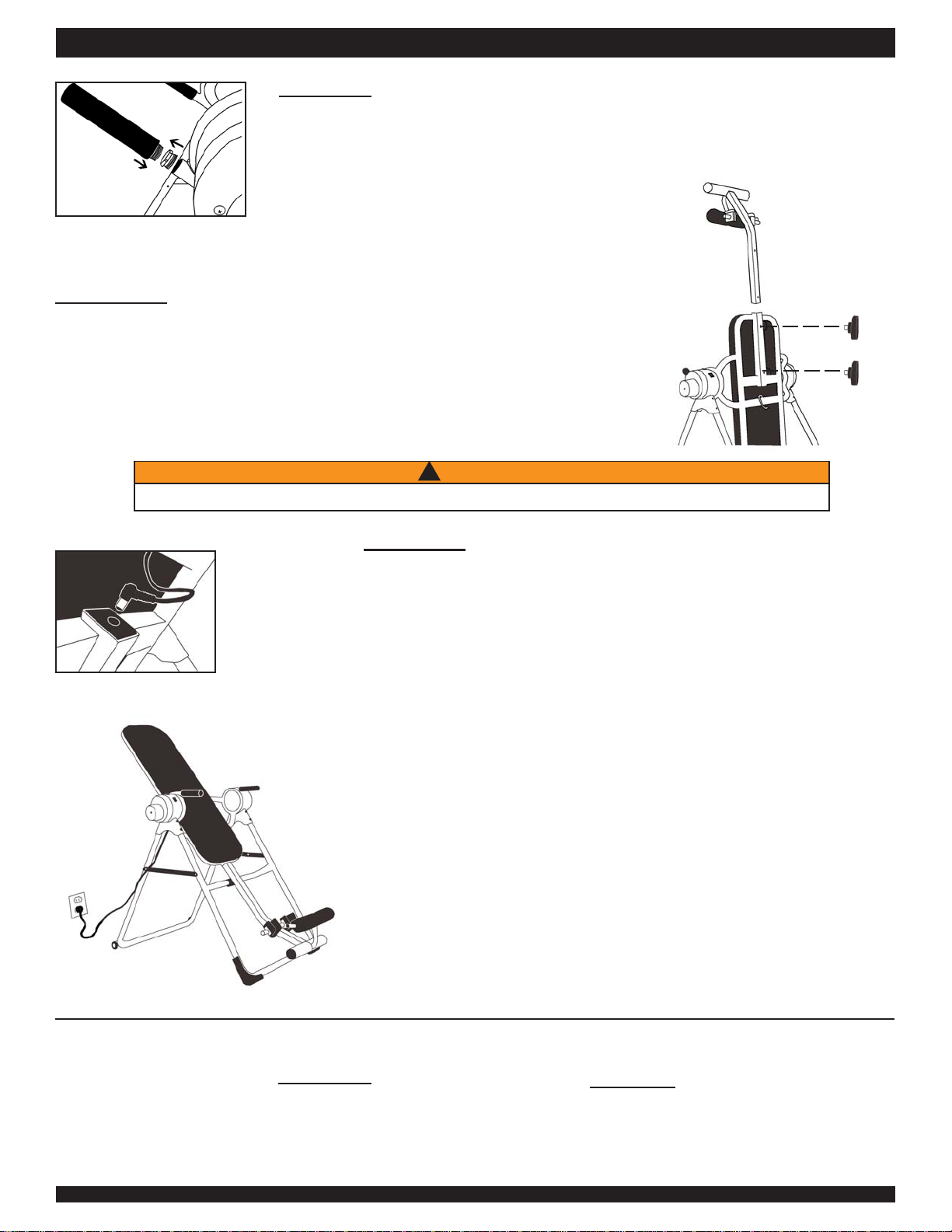
STEP THREE
Secure Main Shaft (PV1003) to Bed Frame (PV1001)
• RemovetheLockingKnobs(PV1005)fromtheholes in the Main Shaft (theyare
pre-assembledforshipping purposes).
• Insert the Main Shaft into the Bed Frame. (See Figure D)
• Line up the holes on the back of the bed with those on the Main Shaft. Insert
and hand-tighten both Locking Knobs to secure the Main Shaft to the Bed
Frame.
STEP TWO
Attach the Handles (PV1008)
• Removethepre-assembledshippingscrews in the Handlearmsanddiscard.
• Insert and screw in the Handles into the arms of both sides of the Bed Frame (Figure C).
Figure E
Figure C
Figure F
Figure D
Locking Knobs
MainShaft
You have completed assembly of the Power VTM Inversion Table
• ReadyourOwner’sManual thoroughlybeforeusingtheinversion table.
• For your reference, the table’s serial number can be found on a sticker
mountedtothemotorhousing.
Failure to secure Locking Knobs could cause head to impact the floor, resulting in serious injury or death.
WARNING!
Table of contents


