HANGCHA CPD10-A User manual

Electrical Forklift Truck
(Electric four-wheel Forklift Truck)
CPD10/15/18/20/25/30-A
CPD10/15/18/20/25/30/35-AC3
CPD10/15/18/20/25/30/35-AC3F
CPD10/15/18/20/25/30/35-AC4
CPD10/15/18/20/25/30/35-AC4F
CPD10/15/18/20/25/30/35-AD2
CPD25-ALC3 CPD25-ALC3F
CPD25-ALC4 CPD25-ALC4F
CPD25-ALD2
OPERATION AND MAINTENANCE
MANUAL
Original Instruction
HANGCHA GROUP CO., LTD.
5 / 2013

FOREWORD
Thanks for you purchasing our A series electric four-wheel forklift truck.
A series electric four-wheel forklift truck is our company‟s new product. It has the character of
small turning radius, beautiful shape, small dimensions, low gravity, good stability, superior
performance.
This operation manual is the explanations that how to use 1.0t~3.5t A series electric four-wheel
forklift truck correctly. It will instruct you how to operate safety and precautionary maintenance. To
ensure safety and exert the truck‟s potential, all the personnel that in charge of operation,
maintenance and management must read this manual thoroughly before starting work with the
forklift.
As the improvements of products of our company, maybe there are some differs between this
operation manual with your forklift truck.
If you have any questions please keep touches with HANGCHA GROUP CO., LTD.sales
department or let the agents know.
Model
Controller
(Drive motor)
Controller
(Pump motor)
Rated capacity(t) / Load
centre(mm)
CPD10-A
Curtis 1244
Curtis 1253
1.0 / 500
CPD15-A
Curtis 1244
Curtis 1253
1.5 / 500
CPD18-A
Curtis 1244
Curtis 1253
1.8 / 500
CPD20-A
Curtis 1244
Curtis 1253
2.0 / 500
CPD25-A
Curtis 1244
Curtis 1253
2.5 / 500
CPD30-A
Curtis 1244
Curtis 1253
3.0 / 500
CPD10-AC3
Curtis 1236
Curtis 1253
1.0 / 500
CPD15-AC3
Curtis 1236
Curtis 1253
1.5 / 500
CPD18-AC3
Curtis 1236
Curtis 1253
1.8 / 500
CPD20-AC3
Curtis 1236
Curtis 1253
2.0 / 500
CPD25-AC3
Curtis 1236
Curtis 1253
2.5 / 500
CPD30-AC3
Curtis 1236
Curtis 1253
3.0 / 500
CPD35-AC3
Curtis 1238
Curtis 1253
3.5 / 500
CPD10-AC4
Curtis 1236
Curtis 1236
1.0 / 500
CPD15-AC4
Curtis 1236
Curtis 1236
1.5 / 500
CPD18-AC4
Curtis 1236
Curtis 1236
1.8 / 500
CPD20-AC4
Curtis 1236
Curtis 1236
2.0 / 500
CPD25-AC4
Curtis 1236
Curtis 1236
2.5 / 500
CPD30-AC4
Curtis 1236
Curtis 1236
3.0 / 500
CPD35-AC4
Curtis 1238
Curtis 1236
3.5 / 500
CPD10-AD2
Danaher ACS48M-35P
Danaher ACS48M-23P
1.0 / 500
CPD15-AD2
Danaher ACS48M-35P
Danaher ACS48M-23P
1.5 / 500
CPD18-AD2
Danaher ACS48M-35P
Danaher ACS48M-23P
1.8 / 500
CPD20-AD2
Danaher ACS48M-35P
Danaher ACS48M-23P
2.0 / 500
CPD25-AD2
Danaher ACS48M-35P
Danaher ACS48M-23P
2.5 / 500
CPD30-AD2
Danaher ACS80M-35P
Danaher ACS80M-23P
3.0 / 500
CPD35-AD2
Danaher ACS80M-35P
Danaher ACS80M-23P
3.5 / 500
CPD10-AC3F
Curtis 1236
Curtis 1253
1.0 / 500
CPD15-AC3F
Curtis 1236
Curtis 1253
1.5 / 500
CPD18-AC3F
Curtis 1236
Curtis 1253
1.8 / 500
CPD20-AC3F
Curtis 1236
Curtis 1253
2.0 / 500

Model
Controller
(Drive motor)
Controller
(Pump motor)
Rated capacity(t) / Load
centre(mm)
CPD25-AC3F
Curtis 1236
Curtis 1253
2.5 / 500
CPD30-AC3F
Curtis 1236
Curtis 1253
3.0 / 500
CPD35-AC3F
Curtis 1238
Curtis 1253
3.5 / 500
CPD10-AC4F
Curtis 1236
Curtis 1236
1.0 / 500
CPD15-AC4F
Curtis 1236
Curtis 1236
1.5 / 500
CPD18-AC4F
Curtis 1236
Curtis 1236
1.8 / 500
CPD20-AC4F
Curtis 1236
Curtis 1236
2.0 / 500
CPD25-AC4F
Curtis 1236
Curtis 1236
2.5 / 500
CPD30-AC4F
Curtis 1236
Curtis 1236
3.0 / 500
CPD35-AC4F
Curtis 1238
Curtis 1236
3.5 / 500
CPD25-ALC3
Curtis 1236
Curtis 1253
2.5 / 500
CPD25-ALC3F
Curtis 1236
Curtis 1253
2.5 / 500
CPD25-ALC4
Curtis 1236
Curtis 1236
2.5 / 500
CPD25-ALC4F
Curtis 1236
Curtis 1236
2.5 / 500
CPD25-ALD2
Danaher ACS80M-35P
Danaher ACS80M-23P
2.5 / 500
© 5/2013 HANGCHA GROUP CO., LTD

CONTENT
Foreword
1. Appearance and the main components........................................................... 1
2. Displays and Controls....................................................................................... 2
Multi-function display........................................................................................... 4
Controls............................................................................................................. 12
Seat................................................................................................................... 17
Seat Aware System(For CE)............................................................................. 20
3. Nameplate and Safety Labels ......................................................................... 22
4. Technical Specifications................................................................................. 24
5. Safety Instructions........................................................................................... 29
6. Forklift Transport,Lifting﹠Towing................................................................. 35
Transport........................................................................................................... 35
Lifting................................................................................................................. 35
Towing............................................................................................................... 36
7. The Structure and Stability of Truck .............................................................. 37
8. Running-in of the new truck............................................................................ 40
9. Daily Maintenance............................................................................................ 41
10. Driving and Operation...................................................................................... 45
Driving............................................................................................................... 45
Traveling............................................................................................................ 45
Turning.............................................................................................................. 45
Stopping or parking ........................................................................................... 45
Loading.............................................................................................................. 46
Stacking load..................................................................................................... 46
Un-stacking load................................................................................................ 47
Check after operation........................................................................................ 47
11. Deposit .............................................................................................................. 48
12. Battery............................................................................................................... 49
13. Maintenance summarization............................................................................ 58
Preventive maintenance schedule..................................................................... 59
Replace the key safe parts termly..................................................................... 66
Table for bolts tightening torque........................................................................ 67
Table for oil used in the truck ............................................................................ 68
14. The use, Install and Safety Rules of attachment ........................................... 69
15. Battery automatic filling water system(Optional) .......................................... 71
16. Related Safety Instruction and Standard(For CE) ......................................... 76
1
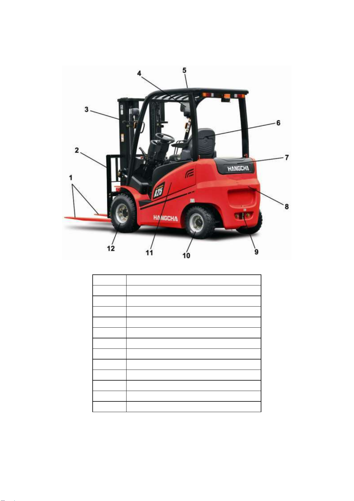
1. Appearance and the main components
Item
Description
1
Fork
2
Load backrest
3
Mast
4
Rearview mirror
5
Overhead guard
6
Driver‟s seat
7
Counterweight cover
8
Counterweight
9
Towing pin
10
Rear wheel
11
Battery behind cover hood
12
Front wheel
2
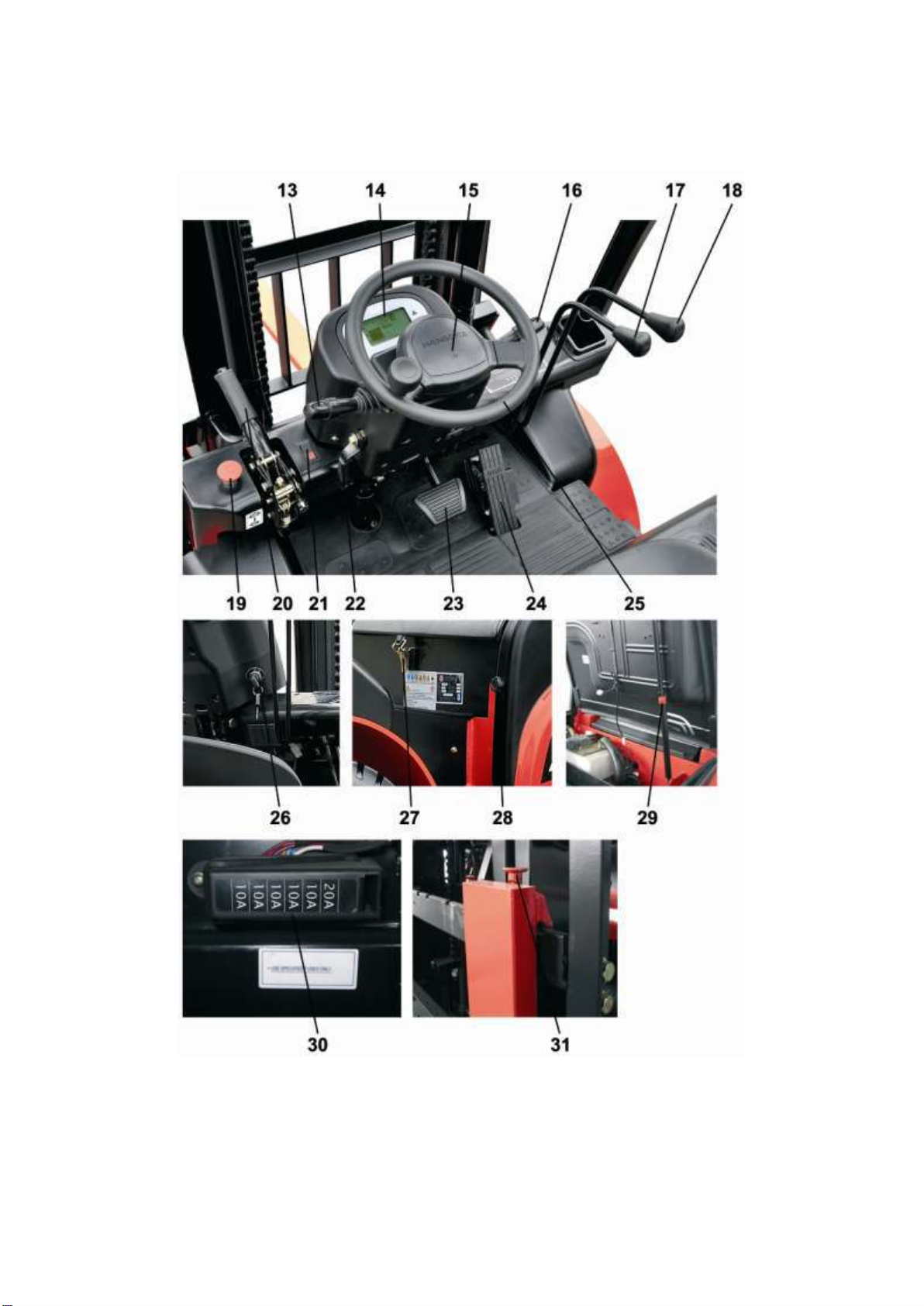
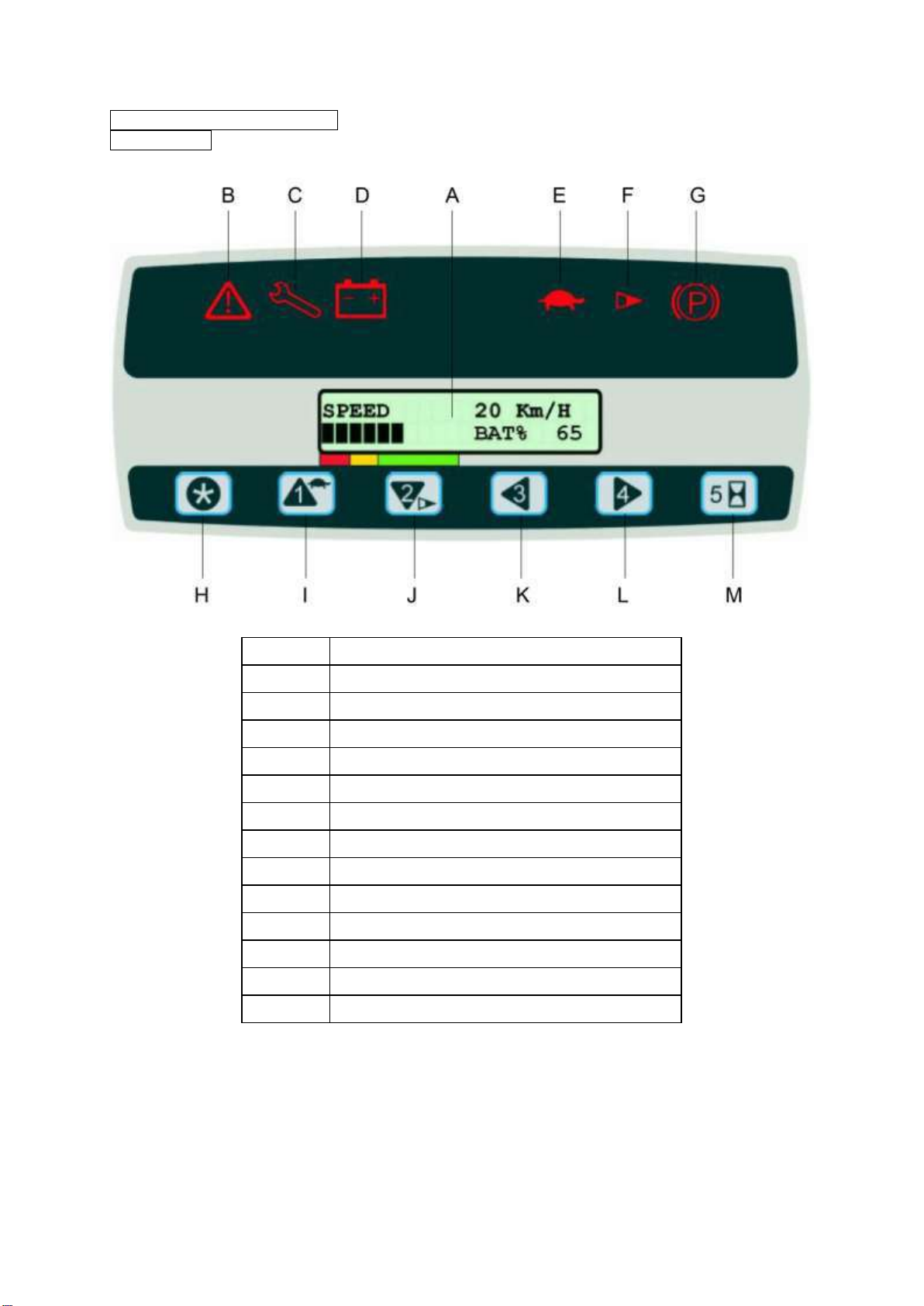
2. Displays and Controls

3
Item
Control / Display
13
Travel direction switch
14
Multi-function display
15
Horn
16
Combination light switch
17
Lifting lever
18
Tilting lever
19
Emergency disconnect switch
20
Parking brake lever
21
Warning light switch
22
Steering column positioning device
23
Brake pedal
24
Accelerator pedal
25
Steering wheel
26
Key switch
27
Locker of battery cover hood
28
Locking bolt of battery side plate
29
Air spring
30
Fuse box
31
Fork stopper
4
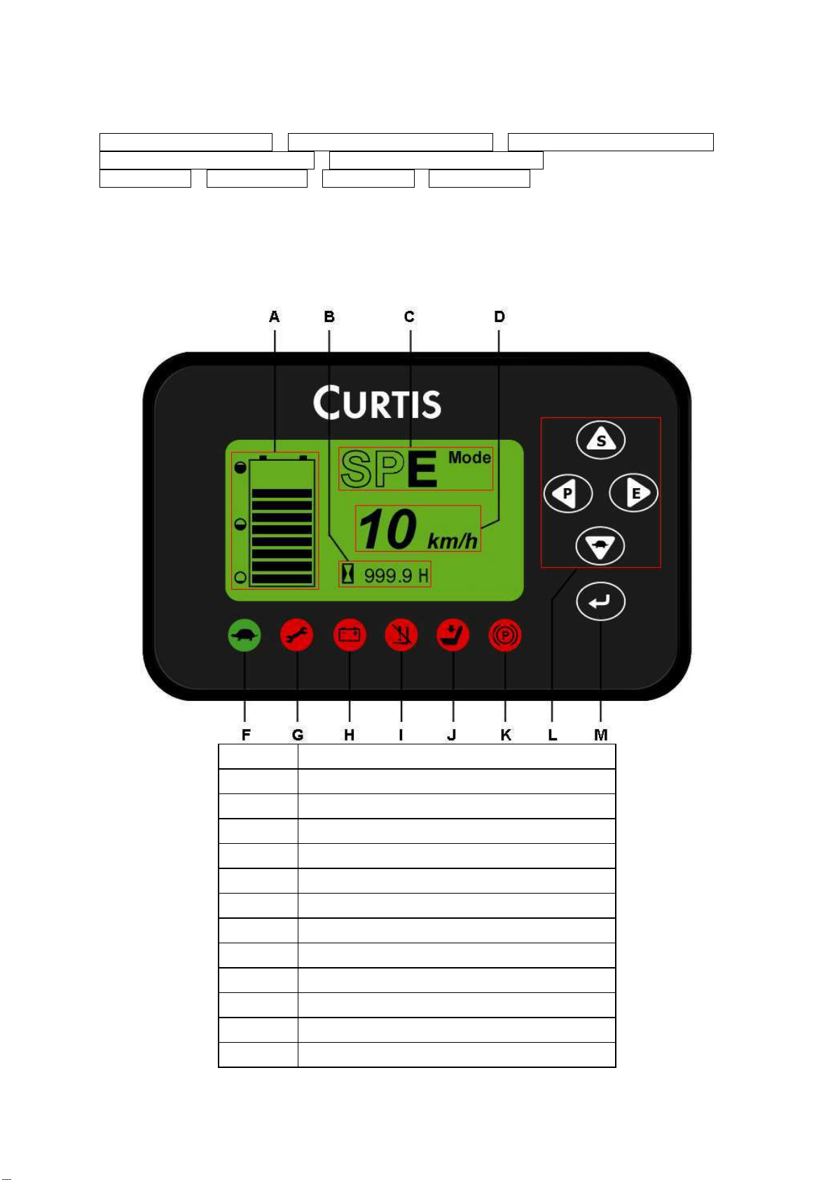
Multi-function display
CPD10/15/18/20/25/30-A CPD10/15/18/20/25/30/35-AC3 CPD10/15/18/20/25/30/35-AC4
CPD10/15/18/20/25/30/35-AC3F CPD10/15/18/20/25/30/35-AC4F
CPD25-ALC3 CPD25-ALC3F CPD25-ALC3 CPD25-ALC3F
The multi-function display shows the battery capacity, the service hours, the operating mode, the
travel speed and fault code information. Graphic illustrations on the multi-function display act as
warning indicators. Through the multi-function display on the right button can also check fault code
and parameter setting.
Item
Display
A
Battery capacity display
B
Service hours display
C
Operating mode display
D
Travel speed or fault code display
F
Crawl speed indicator
G
Fault indicator
H
Battery low capacity indicator
I
Lifting low speed indicator
J
Seat switch indicator
K
Parking brake applied indicator
L
Mode settings or direction choosing button
M
Menu button
5
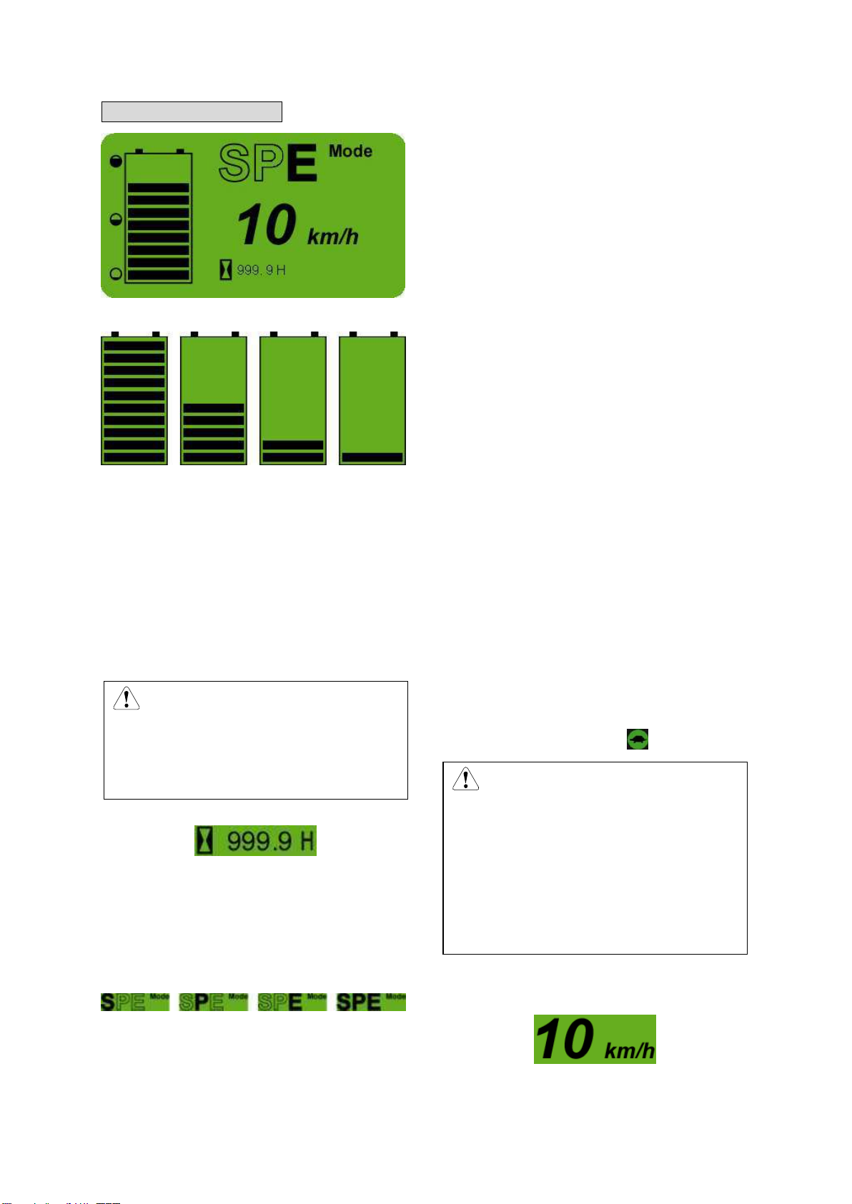
Main display interface
Battery capacity display[A]
Indicates the available residual capacity.
As the following diagram shows, from the left
to the right, the battery decreases from full
state to the only one case, which represents
that the battery leaves only 20%. Thus the
whole battery indicator bar will twinkle, and the
state indicator lamp will be bright, now please
stop working and charge immediately.
CAUTION
Charging in time is very important,
otherwise it will affect the lift-span
of battery!
Service hours display[B]
Hourglass icon indicates that timing function.
When you turn off the key switch, the hour
meter will works and the minimum unit is 0.1
hour.
Operating mode display[C]
As the diagram shows, the pictures from the
left to the right represent the mode of S
mode→P mode →E mode →SPE mode.
S mode is super mode, thus the truck‟s
acceleration, deceleration rate, max climbing
gradient and so on is much higher. It is applied
for transporting mass of good in short time and
climbing big gradient slop,but it costs more
energy,so the mode will not be used in normal
state except emergency.
P mode is power mode. All kinds of index are
lower than that of super mode. It is applied for
the case of long distance transporting and
needing higher power or speed.
E mode is economical mode. All the
parameters are optimized. Working in this
mode can save power so it is applied for a long
time work after charging, and it is suggested to
work in this mode in normal work-time.
SPE mode is safe mode. Thus the max
vehicle speed is limited to about 7km/h. It is
applied for working in busy storage and
cabined room.
SPE mode: The truck is in Safety Mode. In
this mode, maximum traveling speed is limited
to 7km/h. it is very good for working in a crowd
warehouse or other compact space. In this
mode, the slow indicator[F] will be on.
CAUTION
The default mode is mode E. after
power cutting every time, the work
mode resets to mode E no matter
which mode it is before power
cutting, but the switch key is still in
the mode before turn off.
Travel speed or fault code display[D]
Travel speed display
Normal work, display the truck travel speed.

6
Fault code display
Failure occurs, display the controller‟s fault
code.
Note: “TRA” means the traction controller,
“HYD” means the pump controller.
Indicator light
Crawl speed indicator[F](Green)
When the truck in SPE mode, the crawl speed
indicator light up.
Fault indicator[G](Red)
The light up when the controller is wrong or
operation mistake, and the fault code shows in
the main display screen.
Battery low capacity indicator[H](Red)
When there is only one line for the power, the
indicator will be on to remind the user to
charge the battery.
Lifting low speed indicator[I](Red)
When there is 10% power, the indicator is on,
and the mast lifting speed drops, to remind
user to charge the battery as soon as possible.
Seat switch indicator[J](Red)
When operator leaves the seat, the light will be
on, and the truck will be unable to travel or lift.
This function needs the seat to equip with seat
switch (optional).
Parking brake applied indicator[K]
When parking brake applied, the light up.
Button
Mode settings or direction choosing
button[L]
Mode settings
In the main display interface, the button 、
、 、 , corresponding Smode、P
mode、E mode、SPE mode.
For example: In the main display interface,
press the button , the screen shows as
follows:
Direction choosing
In the menu interface, the button 、 、
、, corresponding up、left、right、down
four direction choosing button keys.
Menu button[M]
(1)In the main display interface, press the
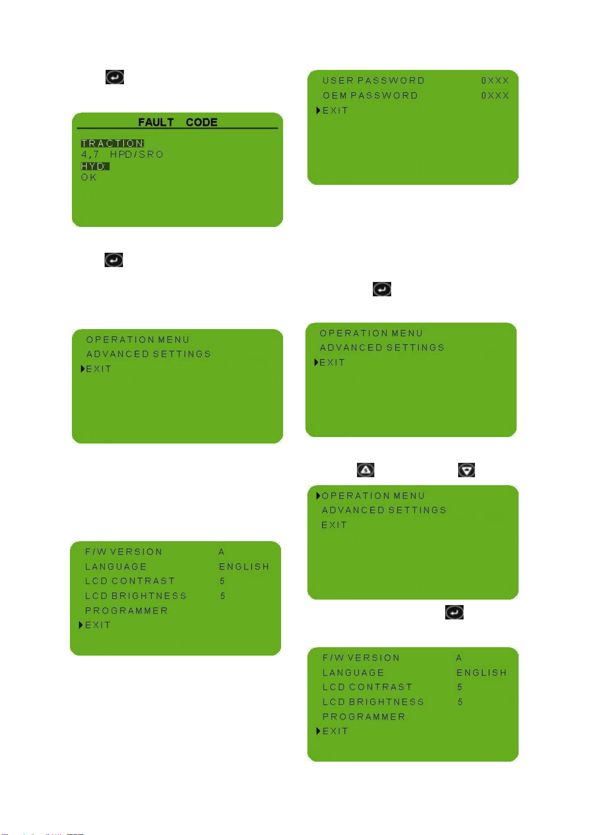
7
button ,and then enter the fault code
interface. The fault code shows as follow:
(2)In the main display interface, press the
button over 2 seconds, and then enter
the main menu .
The main menu includes: operation
menu,advanced settings and exit.
OPERATION MENU
The operation menu includes :Software
version information, language settings, LCD
contrast settings, LCD brightness settings,
programmer settings and exit.
ADVANCED SETTINGS
This menu needs password.
Through the example below shows how to use
the button settings parameter .
For example: The language from english
switch to chinese.
①In the main display interface, press the
menu button() over 2 seconds, and then
enter the main menu .
②Select the “OPERATION MENU” through
up button( ) or down button( ) .
③Press the menu button( ), enter the
opeation menu.
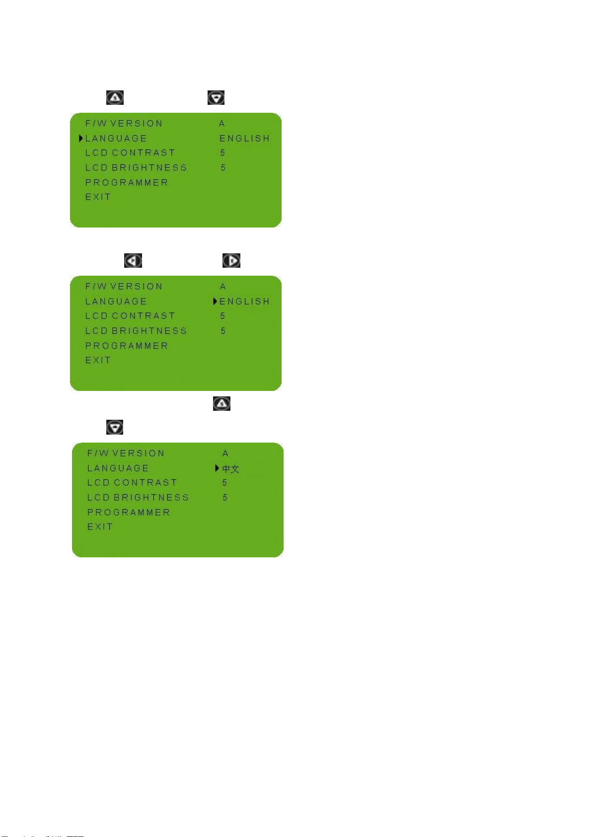
8
④Select the “LANGUAGE” through up
button( ) or down button( ) .
⑤Enter the language setting state through
left button( ) or right button().
⑥Through the up button( ) or down
button( ), select the chinese language.
⑦Refer the steps ⑤④③②①, return the
main display interface.
The language has been set up .
Note: this instrument supports two languages
of Chinese and English, it will set to your
wanted language and if you want to switch the
language, please refer to the above example
for operation.
9
CPD10/15/18/20/25/30/35-AD2
CPD25-ALD2
Item
Display
A
Dashboard display LCD
B
Communicate indicator
C
Error indicator
D
Low battery warning
E
Speed limited indicator
F
Accelerate indicator
G
Parking brake indicator
H
Entrance button
I
Speed limited button
J
Accelerator limited button
K
Backup button
L
Backup button
M
Switch button of hour indication

10
Dashboard display LCD [A]
When turn on the key switch, the system will
self-diagnose, the lamp will lights on one by
one. After self-diagnose, LCD will display truck
speed and battery capacity. You can know
your truck‟s working condition through the LCD
dashboard.
Communicate indicator [B]
Only lights on when record program, usually it
is no use.
Error indicator [C]
When operation is wrong or the truck is in
trouble, error code will display on the
dashboard. The error indicator lights on.
Low battery warning [D]
When battery quantity is lower than 20% of
maximum capacity, the indicator lights are on,
at the same time, buzzer beep. When LED
shows no power, please charge battery as
quick as possible.
Speed limited indicator [E]
When this lamp lights, it meanings the truck
working at low speed mode. The maximum
speed of truck decreased. Press button 1, you
can switch the high speed and low speed
mode.
Accelerate indicator [F]
When this lamp lights on, it means the truck
working at low acceleration mode. The
maximum acceleration decreased. Press
button 2, you can switch the high acceleration
and low acceleration mode.
Parking brake indicator [G]
P
When pulling on the parking brake lever, this
lamp lights on.
Entrance button [H]
This button is no use for operator.
Speed limited button [I]
1
Press this button to switch the high speed and
low speed.
Accelerator limited button [J]
11
2
Press this button to switch the high
acceleration and low acceleration.
Backup button [K]
3
This button is no use for operator.
Backup button [L]
4
This button is no use for operator
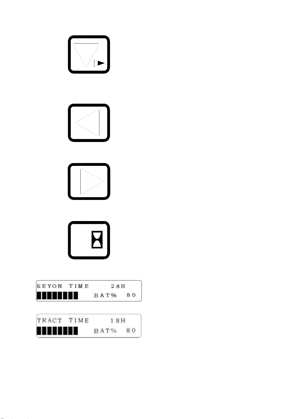
Switch button of hour indication [M]
5
Push this button, it will display the total hours
of truck, as follow figure:
Push again, it switch to the total traction hour.
Push the button once again, it switch to speed
display mode.
12
Controls
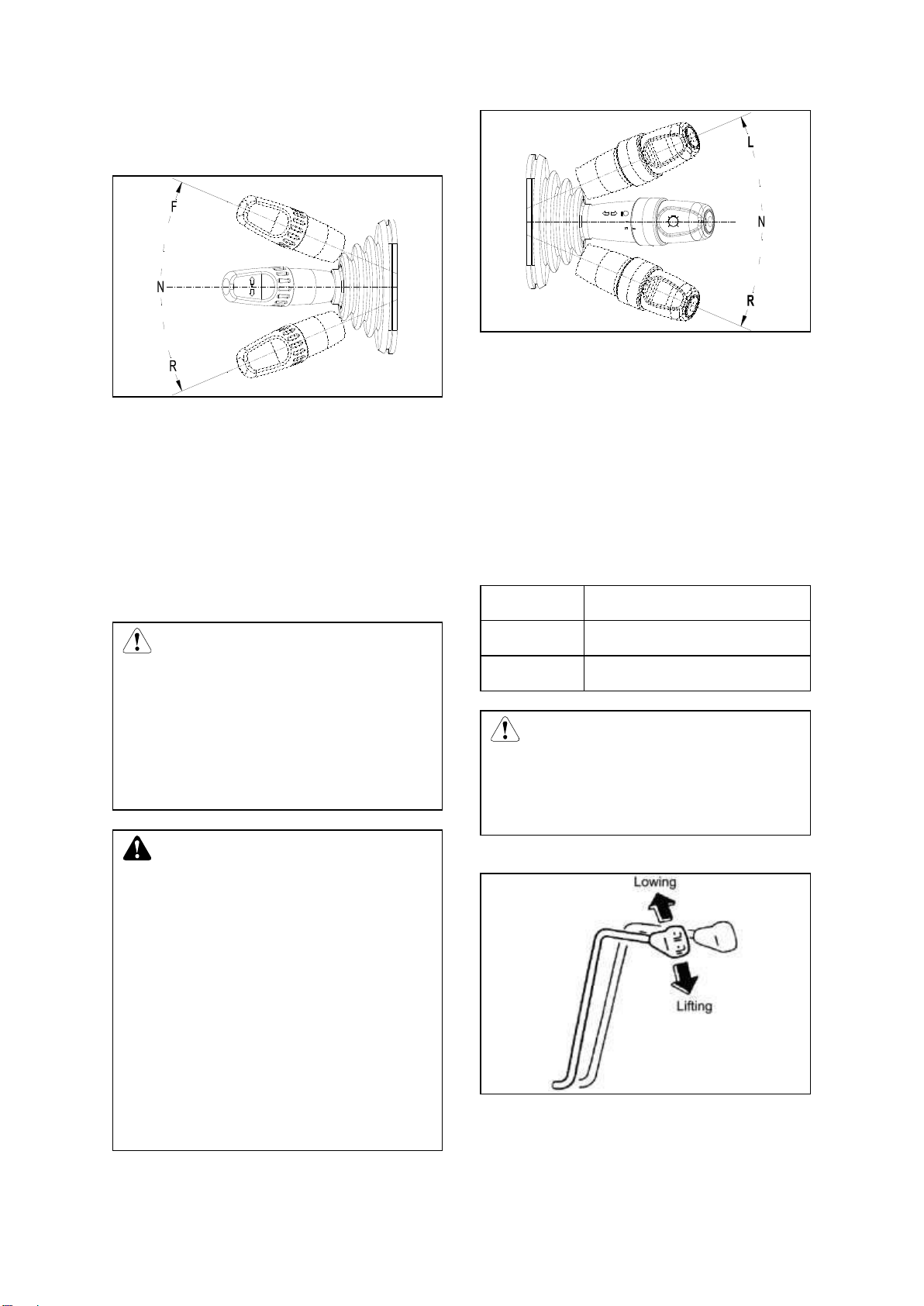
Travel direction switch [13]
Sets the required travel direction.
The travel direction switch is used for
switching between forward and backward
moves. When the travel direction switch is
pushed forward and accelerator pedal pressed,
the forklift trucks moved forward. When the
travel direction switch is pushed backward, the
forklift trucks moved backward.
CAUTION
While traveling, if change the travel
direction switch, electric braking
will operate,speed will lower until
stop,then travel to the opposite
direction.
WARNING
Turning the key switch “on” does
not make the forklift truck move, if
the travel direction switch is not in
the neutral position or the
accelerator pedal is being pressed.
In this case, the travel direction
switch should be returned to neutral
and move you foot from the
accelerator pedal. Then the truck
can be operated.
Combined light switch [16]
Control the turn signal lights, headlights and
front small lights working condition.
This combined light switch is composed of
turning light switch and big/small lamp switch.
Turning light indicates the traveling direction.
When turn on the switch, the lamp flashes.
The light switch has two shifts. First shift small
lights on; second shift headlights and small
lights both up.
Forward
Left turning lamp flashes
Neutral
Lamp goes off
Backward
Right turning lamp flashes
CAUTION
The turn signal switch does not
automatically return to the neutral
position. Reset it by your hand.
Lifting lever [17]
Lifts / lowers the forks.
The forks can be raised or fell by pulling
backwards or pushing the lever. Lifting speed
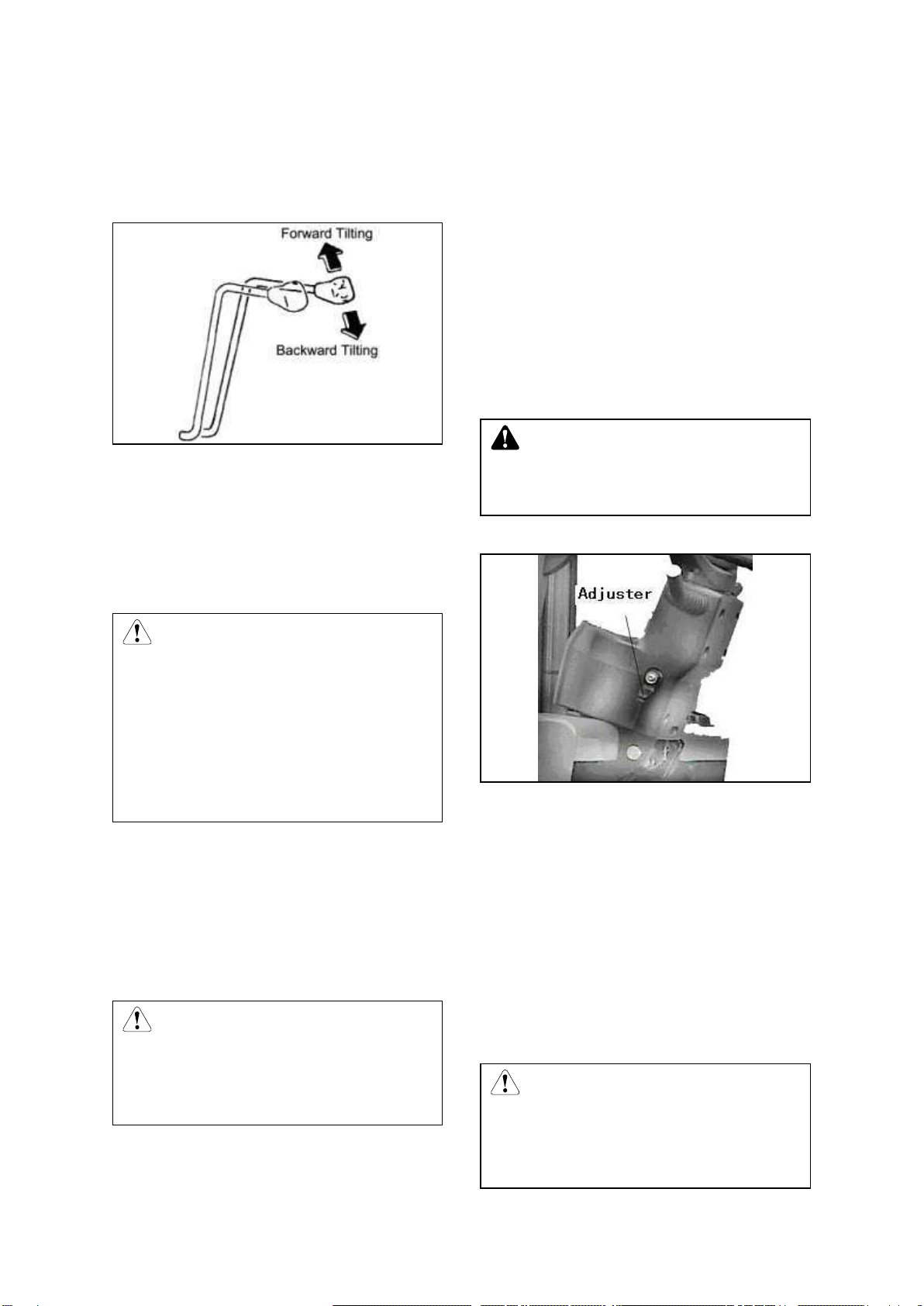
13
can be controlled by tilt backwards angle of
lever and the lowering speed can be controlled
by tilt forwards angle of the lever.
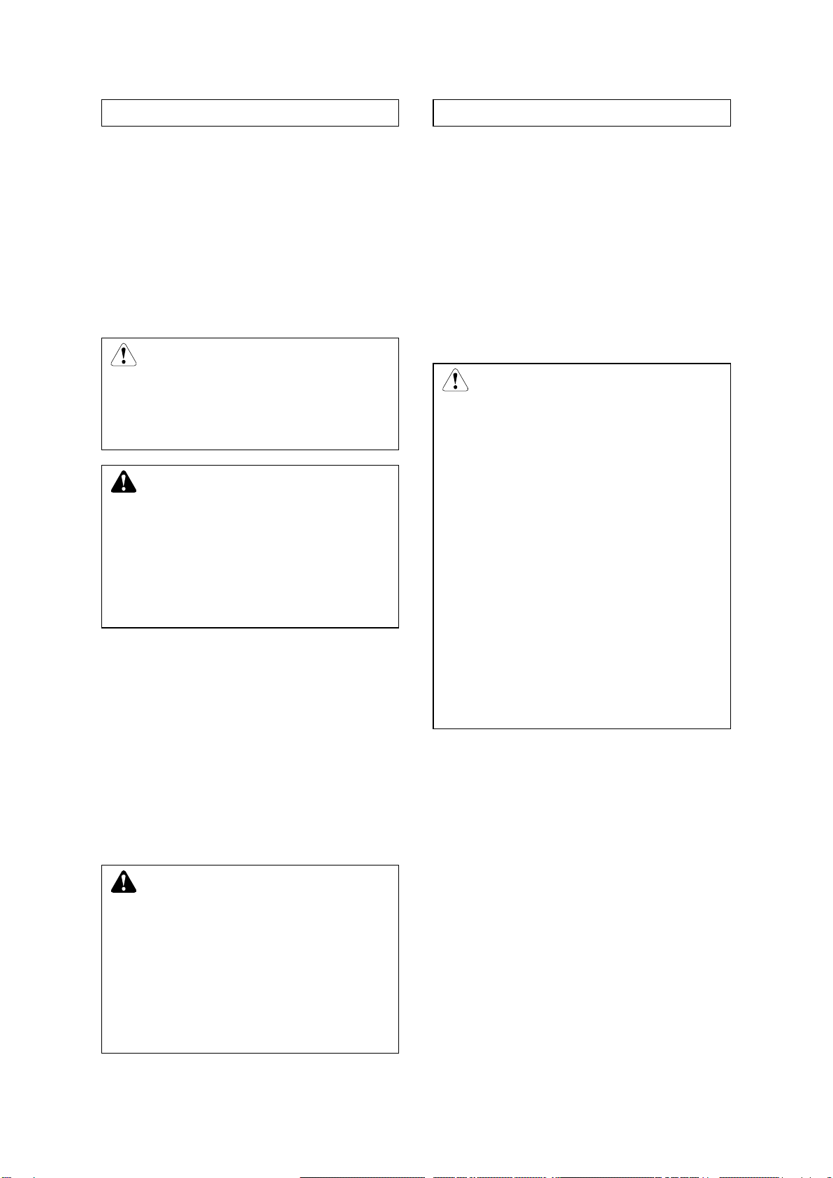
Tilting lever [18]
Tilts the forks forward / backward.
The forks can be tilted by operation of this tilt
lever. Pulling on this lever backwards will tilt
the forks backwards, and pushing it forwards
will tilt the forks forwards. The tilt speed can be
controlled by tilt angle of the lever.
CAUTION
The tilt lock mechanism built in the
hydraulic control valve does not
allow the mast to tilt forwards while
the electricity is being shut down
even if the tilt lever is pushed
forwards.
Emergency disconnect switch [19]
Switches power supply on and off.
When happen emergency, presses down the
emergency disconnect switch, and then the
main power of the truck will be cut off, the truck
stops working.
CAUTION
Please don’t use the emergency
disconnect switch to substitute the
function of key switch.
Parking brake lever [20]
Secures the truck when stationary.
Use this parking brake lever to park the lift
truck. And the parking brakes are applied on
the front two wheels by pulling up on this lever.
To release the parking brakes, move the lever
forwards.
There is a micro switch at the left side of the
parking brake lever, tense the lever makes
running invalid.
For the truck of CE: if you leave the seat
without tensing the lever, it will warn and
remind you to tense the lever.
WARNING
If parking on a grade is unavoidable,
be sure to block the wheel.
Steering column positioning device [22]
Adjusts and fixes the steering column to the
required distance.
The tilting angle of the steering column is
adjustable to suit individual operators. Turn the
hand lever upward to release the steering
column and locked by turning it downward.
Brake pedal [23]
Decelerates the truck.
Press this pedal to slow or stop the truck. At
the same time, the brake light comes on.
CAUTION
No permitted to press the brake
pedal and the accelerator pedal at
same time, otherwise, it is harmful
14
to the traveling motor.
Accelerator pedal [24]
Provides infinitely variable control travel
speed.
As the accelerator pedal is slowly pressed, the
drive motor start turning and the forklift truck
will start to move. According to the force
applied to the pedal, the speed is adjusted with
not steps.
CAUTION
Loosen the accelerator pedal when
truck is working, truck can make
soft brake.
WARNING
Before open the key switch to press
the accelerator pedal, the more
function digital indicator shall show
alarm information. Then you must
release the accelerator pedal.
Steering wheel [25]
It‟s can control the forklift steering.
The steering hand-wheel is operated in the
conventional manner, that is, when the wheel
is turn right, the truck will turn to the right;
when the wheel is turn left, the truck will turn to
the left. The steer wheels are located at the
rear of the truck. These cause the rear of the
truck to swing out when a turn is made.
WARNING
This truck is provided with the
power steering, so heavy
hand-wheel operation is caused
when the steering motor comes to a
stall. To put the power steering in
operation again, restart the steering
motor without delay.
Key switch [26]
Switches control current on and off.Removing
the key prevents the truck from being switched
on by unauthorised personnel.
The key switch has two “on/ off” position, you
should push the Direction switch lever to
neutral and loose the accelerator pedal, then
turning the key switch to “on” position
clockwise.
CAUTION
Turning the key switch “on” does
not make the forklift truck move, if
the Direction switch lever is not in
the neutral position or the
accelerator pedal is pushing.
Error code maybe appear, don’t
worry about it.
The Direction switch lever should
be returned to neutral and move you
foot from the accelerator pedal.
Then the truck can be operated.
Then the error code should be
disappeared.
Locker of battery cover hood [27]
Fixed the battery cover.
Locking bolt of battery side plate [28]
Locking the side plates on both of the battery
box.
Air spring of battery cover [29]
When the battery cover hood opened, to
support the cover hood. When closed the
cover hood, press the red button, at the same
time hard to press the cover hood.
Fuse box [30]

15
CAUTION
When replace a new fuse, please
choose the same capacity fuse of
the old one.
Fork stopper [31]
Fork stoppers are locked the forks in position.
To adjust fork spacing, pull up fork stoppers,
turn 90°and shift the forks to the desired
position. The fork spacing should be adjusting
according to loads to be handled.
WARNING
The forks should be set
symmetrically to machine centerline
and fork stoppers should always be
locked again.
There are one gap on the below
beam. It is used to attach goods.
It is forbidden to lock the fork on the
gap position, to prevent the fork fall
off from the gap.
In the middle of the above beam, a
bolt used to prevent fork works
here. Please change the bolt as
soon as it is damaged.
Change fork
Take down the old fork: Firstly, locate the fork
to the middle, decline it to the ground and
make the mast forward, then operate the truck
traveling backward, the fork will be taken
down.
Change new fork: Firstly, make the fork dead
against the truck and forklift‟s mast to the
bottom, then operate the truck traveling
forward, aim at the two gaps and beams, and
raise the mast.Adjust the position of the fork.
Battery cover hood
The cover hood can be swung up fully to
provide easy examining and maintenance of
the storage batteries.
You can lift up the cover hood with little effort
with an aid of cover hood damper. To lock the
cover hood, push down on the front of cover
hood until it covered.
CAUTION
Be careful do not to catch you
fingers in the cover hood when
closing it.
Depress the spring insurance
before you close the cover hood,
then press the head of the cover
hood.
Overhead guard
The overhead guard used is strong enough to
16
meet safety standard, and protects the
operator from falling materials. The top gap is
used to lift the batteries. It is forbidden for use
a truck that does not with safeguard.
L.H. & R.H. battery side plate
The battery is covered hood, one left and one
right. When you want to take off the hood, you
should take off the locking bolts at first.
Safety step and safety grip
The safely steps are provided on both side of
the truck body. The safely grip is provided on
the front left pillar of the overhead guard. Use
the safely step and safely grip when mounting
and dismounting the truck.
Brake fluid reservoir cup
The brake fluid reservoir cup is located at the
meter board.
CAUTION
The brake fluid is poisonous, be
careful do not drop down. When add
brake fluid, be careful do not let dirt
and other thing drop into reservoir
cup.
Hydraulic oil reservoir cap
The hydraulic oil reservoir cap is located at the
right rear end, below the battery hood; open
the right side battery hood when adding oil.
After fill in clean hydraulic fluid, tighten lock the
cap.
Air leakage plug
There is an air leakage plug on the oil tank to
let air in the tank goes out. You‟d better often
check the plug and see whether been jammed.
Head lights and combination lights
Two headlights and combination lights (turn
signal, show width lamp) are installed at the
front side of the truck. Take care of the lights,
and wipe dirt, if any, and replace any damaged
light immediately.
Rear combination lights
The combination lights at the rear side serve
as turn signal, show width lamp, brake lamp,
and back-up lamp. Pay attention to keep them
from being damaged or covered with dust, if
any, clean or replace immediately.
Rear big lamp [For CE or Option]
The rear big lamp is set on the safeguard. If it
is broken, please replace a new one at once.
Rear big lamp switch [optional]
Rear big lamp switch (push\pull) has only one
shift.
×—Means connected
Connector
Position
Battery
Far light
0
×
1
×
×
CAUTION
This light does not relate to key
switch position, so please don’t
forget to turn off the rear big lamp
when you leave the truck.
This manual suits for next models
45
Table of contents
Other HANGCHA Forklift manuals

HANGCHA
HANGCHA CPCD30/35-XW43E-RT Quick start guide

HANGCHA
HANGCHA J Series User manual

HANGCHA
HANGCHA CBD20-AMC1 Installation guide

HANGCHA
HANGCHA CBD15-A2MC1 User manual

HANGCHA
HANGCHA XF Series Quick start guide

HANGCHA
HANGCHA R Series User manual

HANGCHA
HANGCHA XF Series User manual

HANGCHA
HANGCHA XE Series User manual

HANGCHA
HANGCHA XC Series User manual


