en-4
• Some specialty models onto which a heavy
attachment is mounted may not be
equipped with the mast forward tilt con-
trol. Confirm with a Toyota dealer in
advance.
• Once you have mounted or replaced any
attachment on a forklift, ask a Toyota
dealer for an inspection.
• If you use two or more removable attach-
ments alternately, the heaviest one should
be used to carry out matching (SAS set-
ting). Contact your Toyota dealer to
request compatibility matching.
• When attaching an attachment to a model
without forks, the attachment must be
compatible with the model. Contact your
Toyota a dealer to request compatibility
matching.
When the forks are elevated to the maximum
height, a high pressure (relief pressure) may
remain in the lift cylinder. This high pressure
causes the vehicle to judge that it has a high load
even if there is no load. As a result, the mast will
be stopped from tilting forward. In this case,
lower the forks slightly (to release the pressure)
and the mast may be tilted forward.
Active mast rear tilt speed control
• At a high lift height, the mast has a back-
ward tilt speed controller (slow down) irre-
spective of the load. When lowering from a
high lift height to a lower lift height while
tilting the mast backward, the control speed
will not change.
• At a low lift height, the mast can be tilted at
full speed even if there is a load. If the mast
is tilted backward at a low lift height with
the tilt knob switch pressed, the mast has the
backward tilt speed controlled (slowed
down) as long as the tilt lever knob switch is
pressed. (Except mini lever/joy stick mod-
els)
• If the low lift height is then changed to a
high lift height while tilting the mast back-
ward, the control speed will not change as
long as the tilt lever knob switch is pressed.
The mast may be tilted backward at the full
speed so long as the tilt lever knob switch is
not pressed.
Key-lift interlock
When the ignition switch is turned to OFF and
lowering the lift lever, the forks will not lower.
However, by sitting on the normal seated posi-
tion and turning the ignition switch to ON, the
forks will lower even when the engine is off.
(Except mini lever/joy stick models)
Active steering synchronizer
If the steering wheel knob is not angularly
matched with the steer tires, such out-of-posi-
tion will be automatically corrected while turn-
ing the steering wheel. Thus, the knob is kept at
a constant position relative to the steer tires.
If SAS feature should fail:
The SAS models are equipped with a controller,
sensors and various actuators. If any of these are
found not to be operating normally, it will tell
you that:
• Steering wheel knob is out-of-position may
not be corrected.
• Functions such as Automatic forks levelling
control, Active mast front tilt angle control,
Active mast rear tilt speed control may not
be operated.
• Swing lock cylinder may not be unlocked.
If any of the phenomena referred to above
should take place.
• Diagnosis lamp will light up or blink.
• Error code will be displayed in the hour
meter.
Thus, the operator will be informed. In such
an event, move the vehicle to a safe location
and ask a Toyota dealer to inspect and repair.
Action to be taken in emergency
Move the vehicle to a safe location and ask a
Toyota dealer for a repair.
If any phenomenon different from normal oper-
ations (failure to run or the like), among others,
should take place, ask a Toyota dealer for an
inspection.
Once a torque converter model has its control
lever abnormal, it is impossible to manually
operate the vehicle, which need be towed,
accordingly.
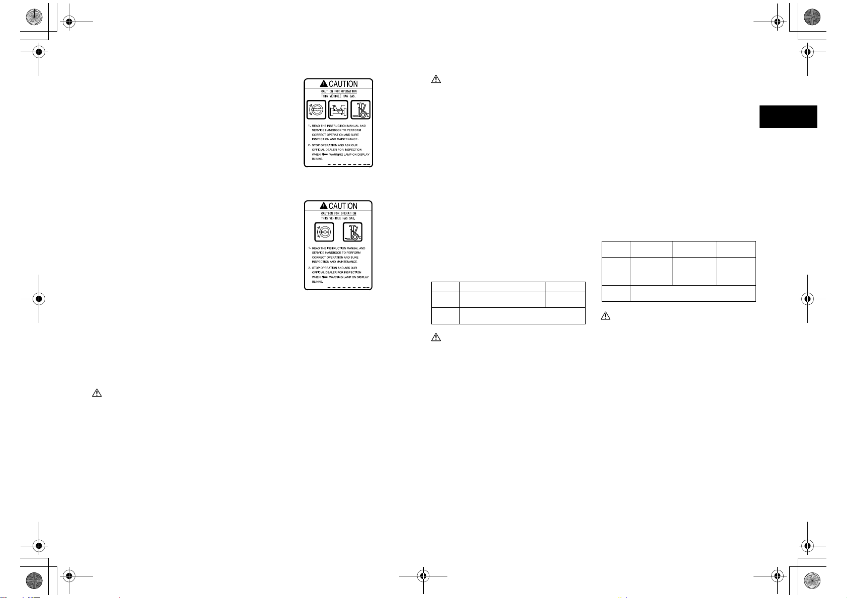
OPS System
The OPS (Operator Presence Sensing) System
prevents traveling and load handling operations
when the operator is not seated in the operator’s
seat.
If the operator leaves the operator’s seat while
the vehicle is operating, the OPS lamp will light
up, and a buzzer will sound for one second to
warn the operator that the OPS System will be
activated. If the operator leaves the operator’s
seat for longer than two seconds, the OPS Sys-
tem will be activated and traveling and load
handling operations will be stopped. However,
if the operator returns to the normal seating
position within two seconds, the OPS System
will not activate and will allow travel and load
handling operations to continue.
Again, if an abnormality occurs to the OPS Sys-
tem, the diagnosis lamp will blink to warn the
operator. In this case, the OPS System may have
malfunctioned. Contact your Toyota dealer to
request an inspection.
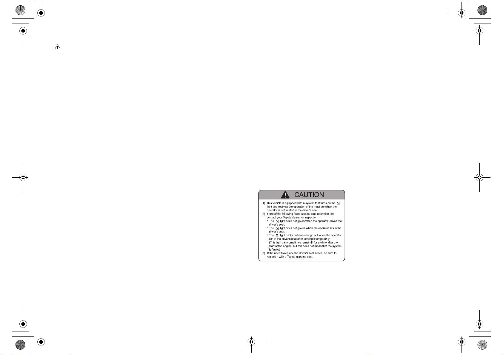
This forklift is equipped with an OPS (Operator
Presence Sensing) System. Before operating the
forklift, check that each of the System’s func-
tions is working correctly.
Travel OPS Functions
If the operator leaves the seat while the vehicle
is traveling, the OPS lamp will light up, and two
seconds later, traveling will be stopped. How-
ever, this does not apply the brakes to stop
travel. (If the operator returns to the normal
seating position within 2 seconds, traveling can
be continued.)
If the OPS System is activated while driving up
a slope or incline, the drive to the front wheels is
stopped and consequently the vehicle will roll
back down the slope incline. To avoid this prob-
lem, make sure to sit on the seat at all times.
If more than 2 seconds has elapsed, apply the
brakes, return the control lever to the neutral
position and sit on the seat again.
Load Handling OPS Function
Forklifts with a standard lever
If the operator leaves the seat during operations,
the OPS lamp will light up, and two seconds
later, load handling operations will be stopped.
(If the operator returns to normal seating posi-
tion within 2 seconds, loading can be contin-
ued.) If the operator leaves the seat while
operating the control lever, loading can be con-
tinued for 2-4 seconds.
If load-handling OPS is activated when the lift
lever is in the lowering position, move the lever
to a position other than the lowering position
and return to the normal seated position to deac-
tivate load handling OPS. If load-handling OPS
is activated when the lift lever is in a position
other than the lowering position, load handling
OPS is deactivated 1 second after the operator
returns to the normal seated position.
Forklifts with a mini lever/joy stick lever
(Option)
If the operator leaves the seat during load han-
dling operations, the OPS lamp will light up,
and two seconds later, load handling operations
will be stopped. (If the operator returns to the
seat within 2 seconds, load handling operations
can be continued.)
To resume load handling functions, return to the
seat and return all of the levers to the neutral
position.
OPS Operation Functions
If the operator leaves the seat, a buzzer will
sound for approx. one second (“pii”) and the
OPS lamp will light up and inform the operator
that the OPS System is active. If the operator
returns to the normal seating position, the OPS
lamp will turn off.
01_A5028-0EA04_En.fm 4 ページ 2012年12月6日 木曜日 午後12時42分